week3. Computer-Controlled Cutting
Assignment
Group assignment
- do your lab’s safety training
- characterize your lasercutter’s focus, power, speed, rate, kerf, joint clearance and types
Individual assignment
- design, lasercut, and document a parametric construction kit, accounting for the lasercutter kerf, which can be assembled in multiple ways, and for extra credit include elements that aren’t flat
- cut something on the vinylcutter
Group assignment
For more information about group projects, please see the group project page on the FabLab Kannai website.
Group assignment page is here
Safety training
Before starting the laser cutting work, the instructor reminded us of the following safety measures.
WARNING
- Do not leave the laser cutter unattended while it is cutting.
- Check the location of the fire extinguisher and make sure it is ready to use.
- Before starting the cutting process, be sure to turn on the exhaust fan and compressor.
- Do not process materials that produce toxic or corrosive gases (such as PVC).
- Do not stare at the intense light.
Characteristics of laser cutters
Our Laser cutter
The following is information about the laser cutter used at Fablab Kannai. 
Universal VLS 2.3
- Work area is 406x305x102mm(16"x12"x4")
- 30W CO2
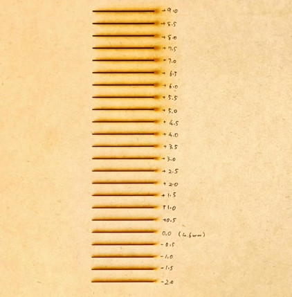
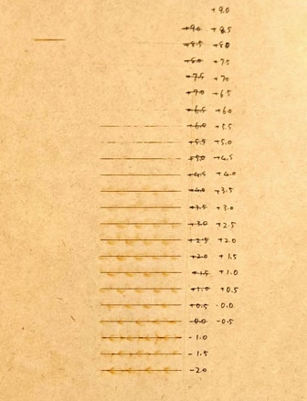
Focus
When adjusted in 0.5mm increments, the cut became thicker the further the focal length of the laser was. If the focal length was too far away, it became impossible to cut. As a result, we decided to use a focal length of 0.00mm.
Power,Speed,Rate
The best setting for 3mm cardboard was Power60%,Speed10%,Rate250PPI 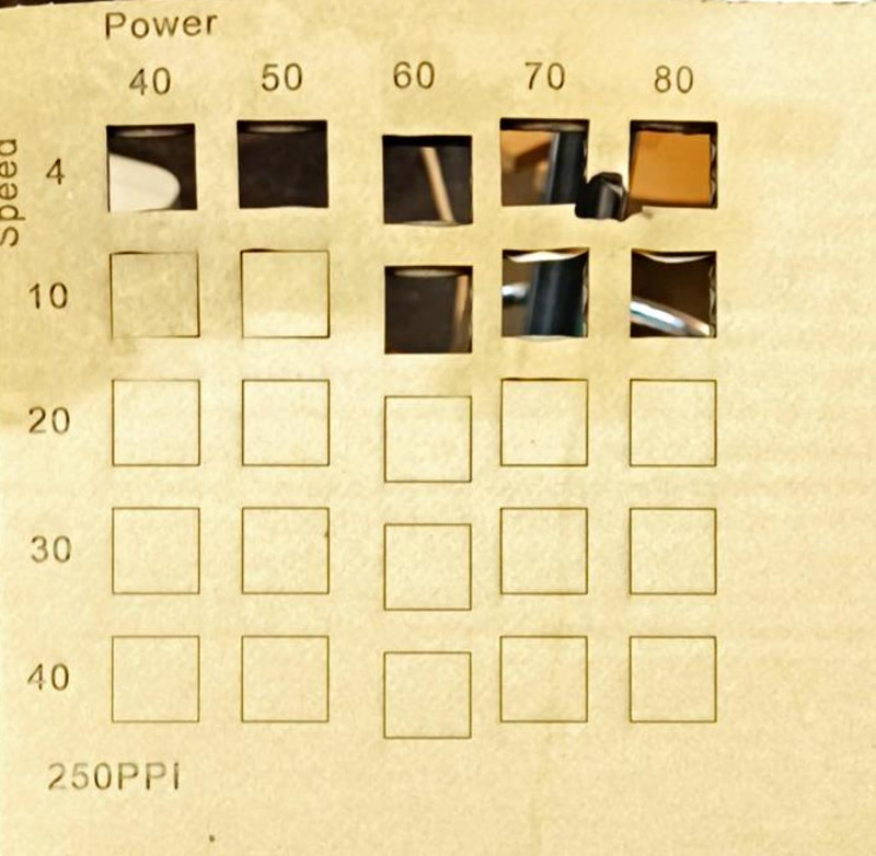
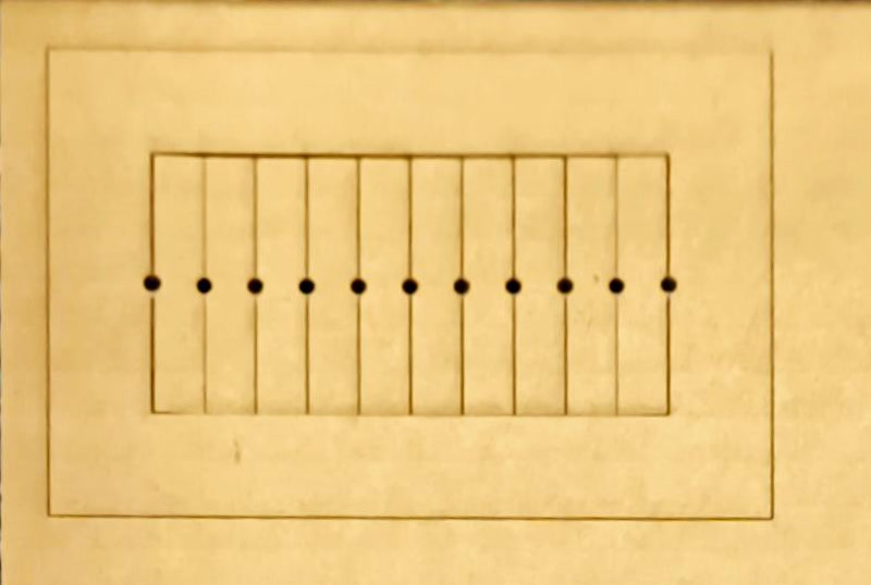
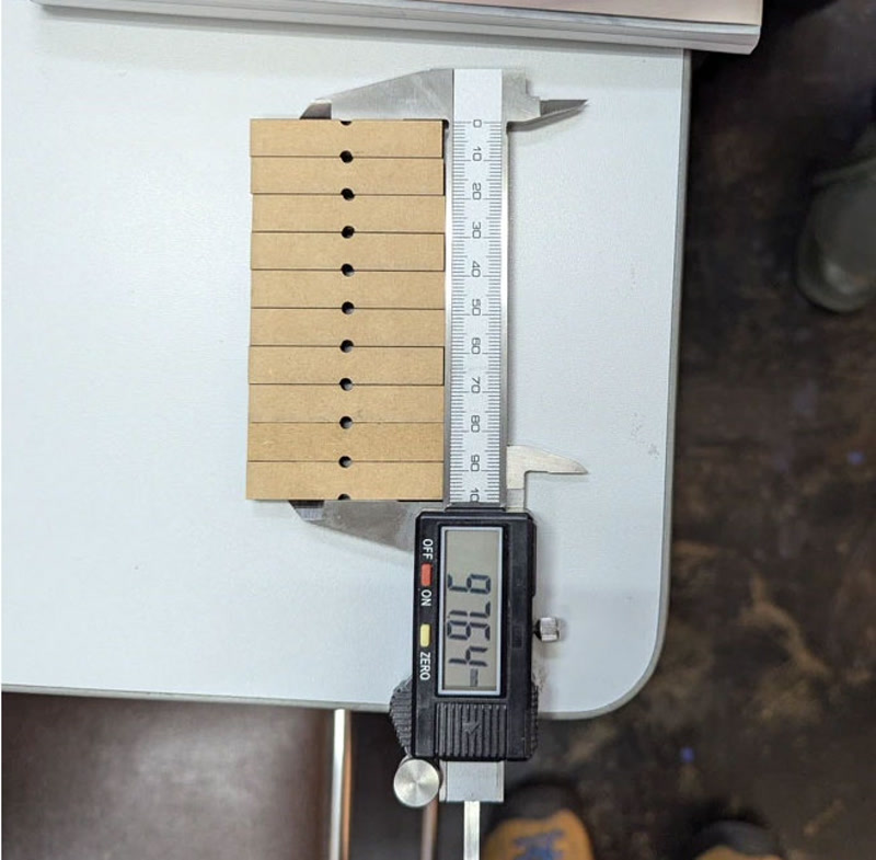
Kerf
Kerf for our machine is 0.227mm.
The following image is data used to clarify the kerf of a laser cutter.
In order to reduce the error when measuring with a caliper, we tried to find a value 10 times the actual kerf by measuring 10 rods.
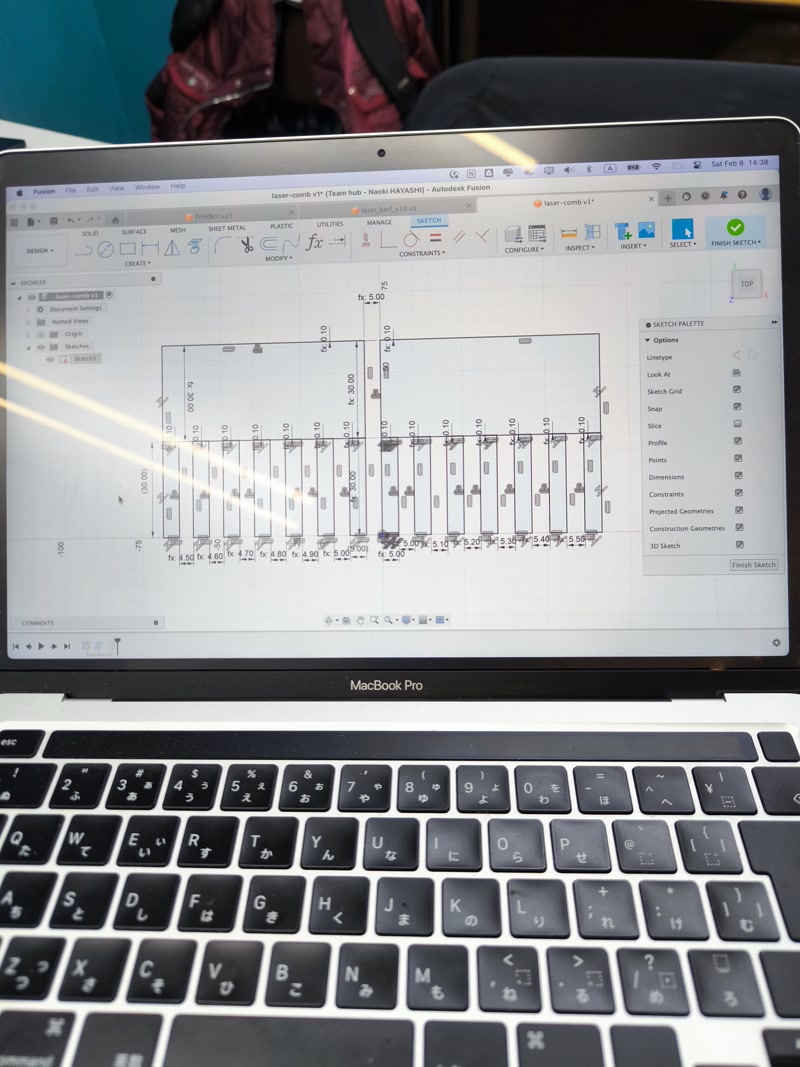
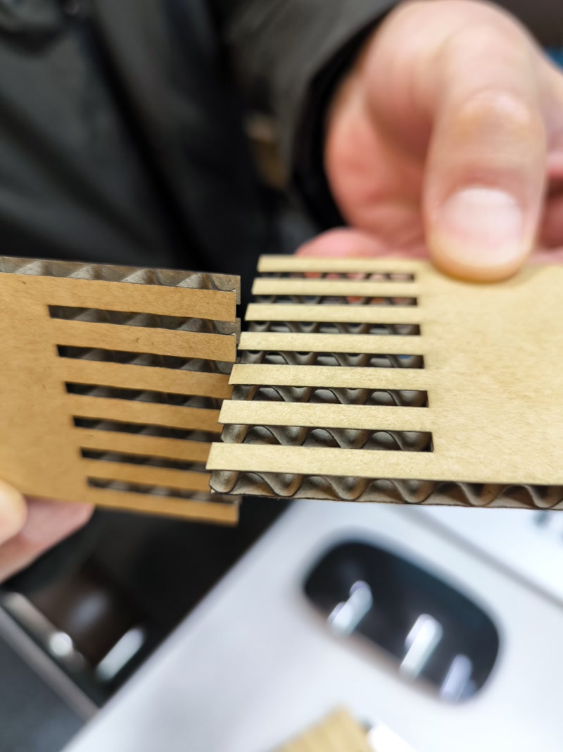
Joint clearance
0.1mm joint clearance is the best for our machine.
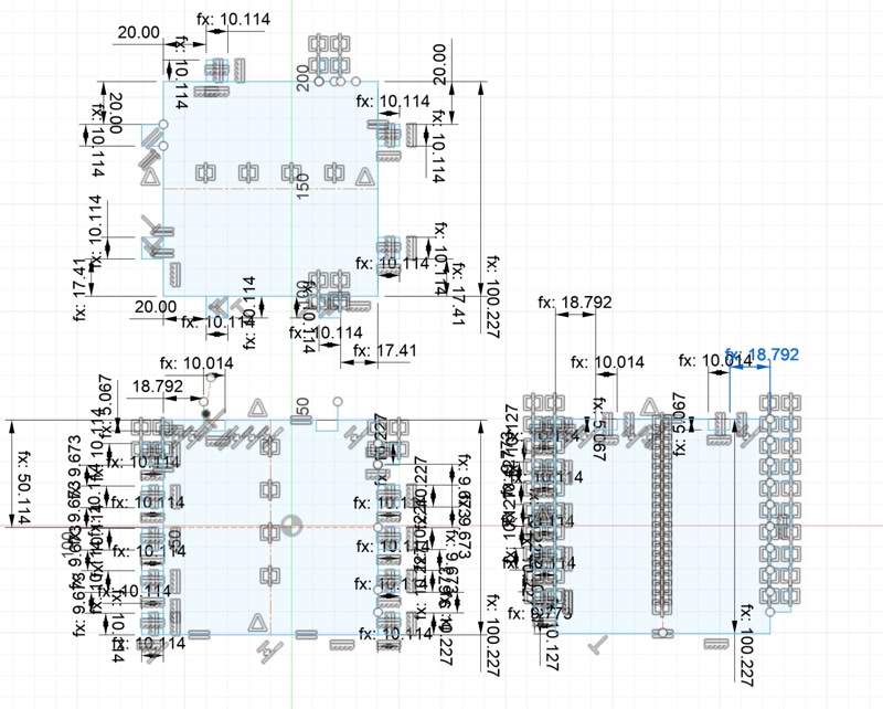
The following data was used to create the joint for the clearance test. Before setting the parameters, it was necessary to measure the actual thickness of the cardboard, which was 5.18 mm.
Individual assignment
Parametric construction kit
Create a shape
In Fusion, first create a shape with a square and a joint added. 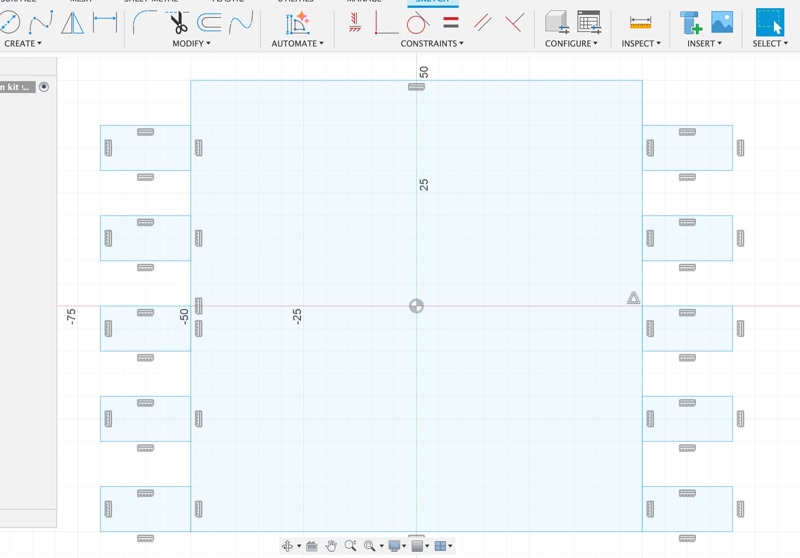
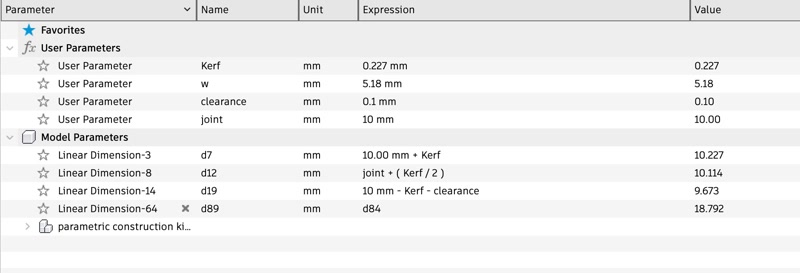
Set parameters
Set the three laser cutting parameters of “thickness”, “clearance”, and “kerf” for the cardboard. 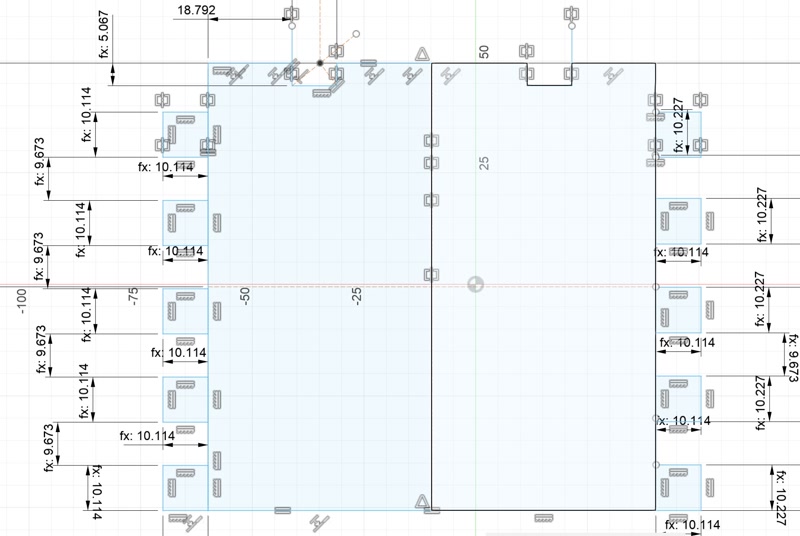
Create a other shape
I also design the other shape that the finger joint will connect to. 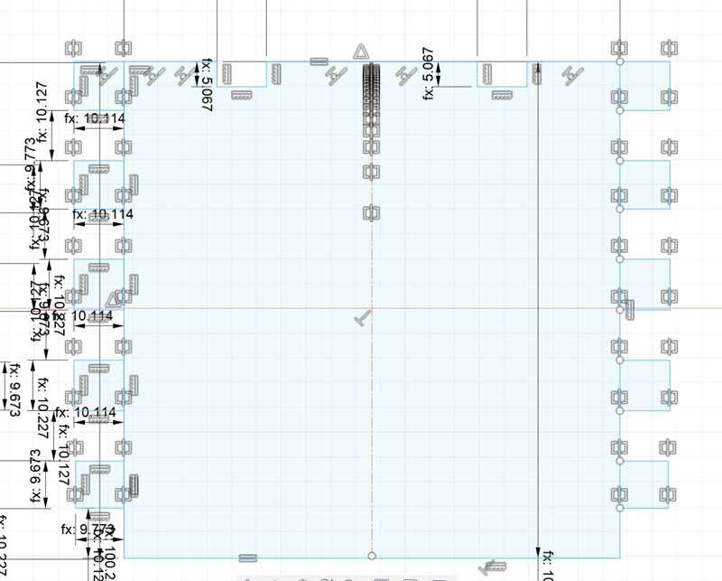
Create a lid
I design the lid. 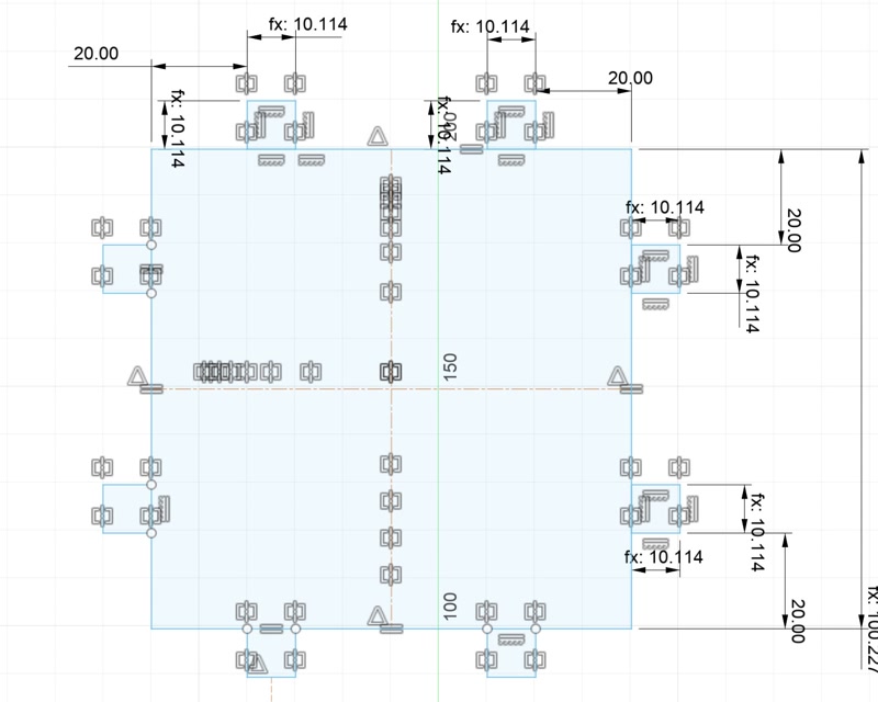
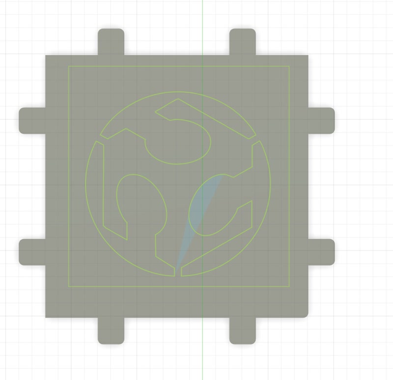
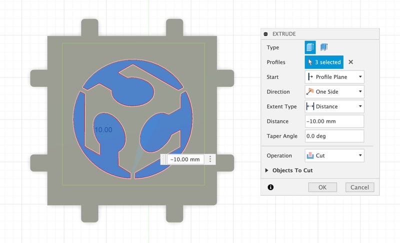
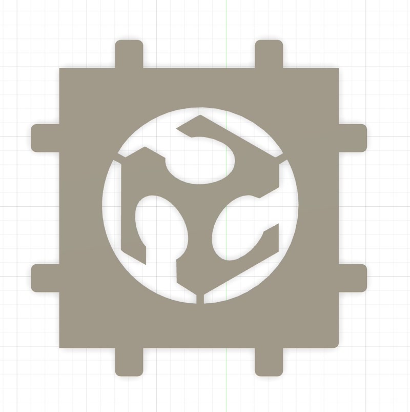
Put a design on the lid
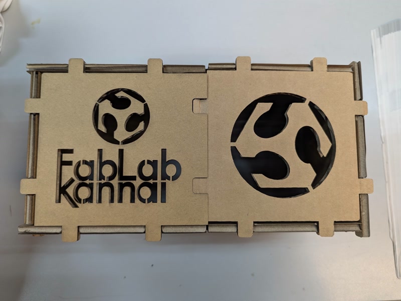
In order to put the Fab Academy logo design on the lid, the logo in svg format is inserted on the lid and then cut out in the shape of the logo using extrusion.
Output in SVG format
Output in SVG format for laser cutters. 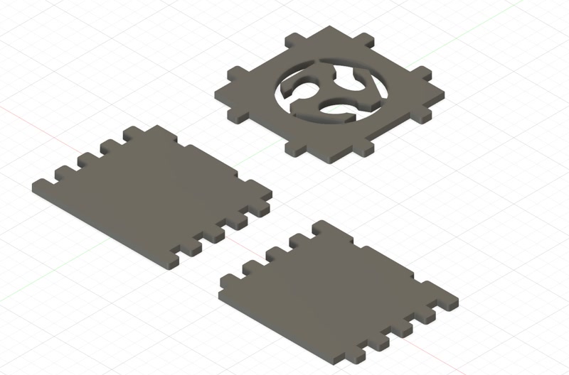
Outputted svg files


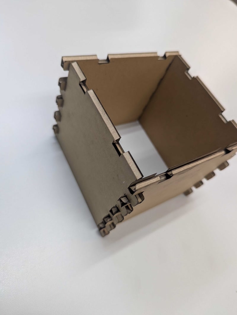
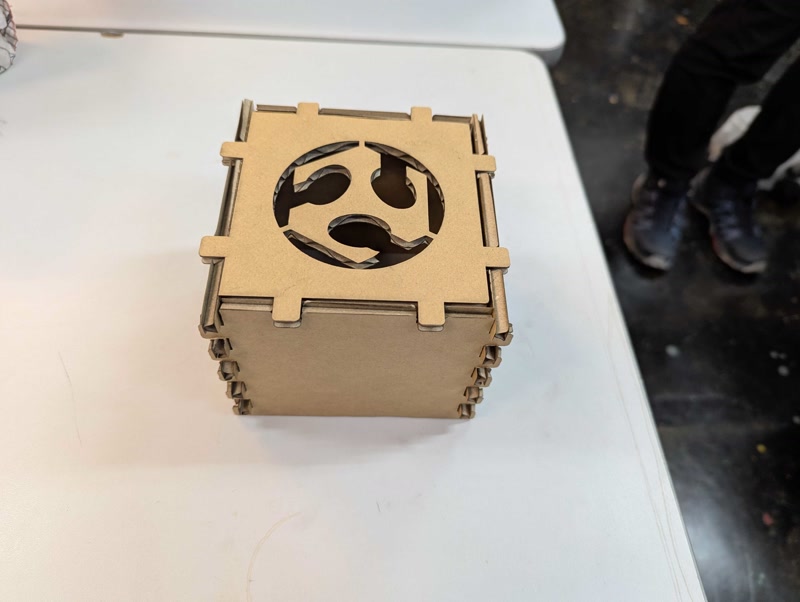
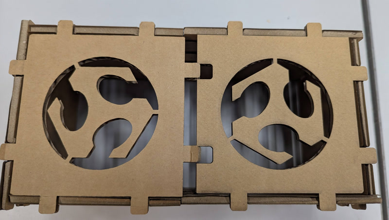
Assembly
Assemble the parts cut out with the laser cutter.
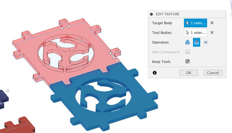
Create a lid2
A problem was uncovered. Since the current parts are not enough to meet the challenge of assembling in multiple ways, we create another part.
First, copy the lid, create lid2, overlap only the joint parts, and cut the overlapped parts using “Modify > Combine”.
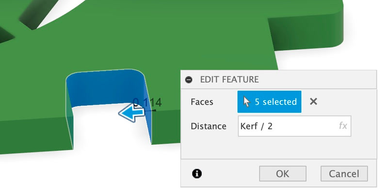
Next, increase the cut portion of lid2 by half of the “Kerf” by using “Modify > Offset Face” to adjust the engagement.
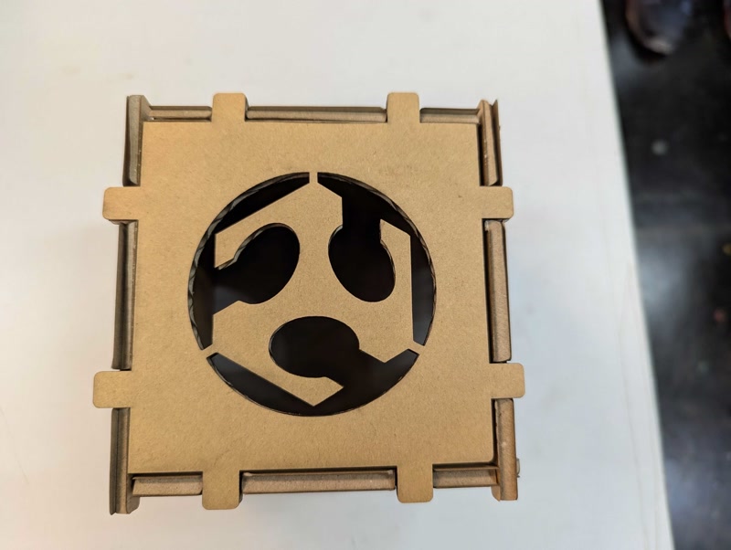
Assembly2
I assembled the parts cut out by the laser cutter in a different way. there is a gap between lid1 and lid2. But I forgot to make lid2 larger by the width of the joint parts!
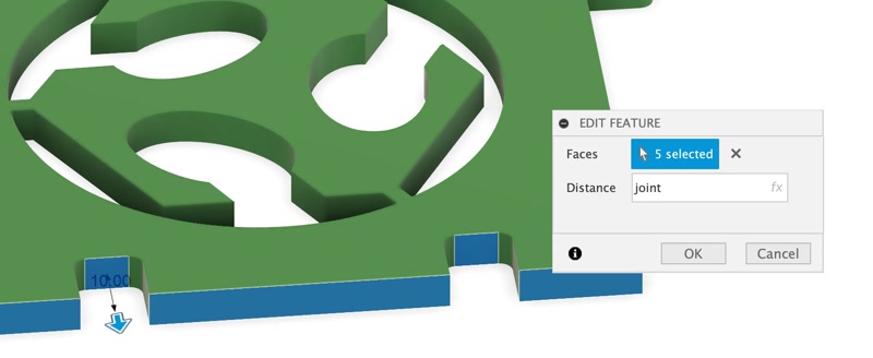
Modify a lid2
Increase the joint surface of lid2 by the joint amount using “Modify > Press Pull”.
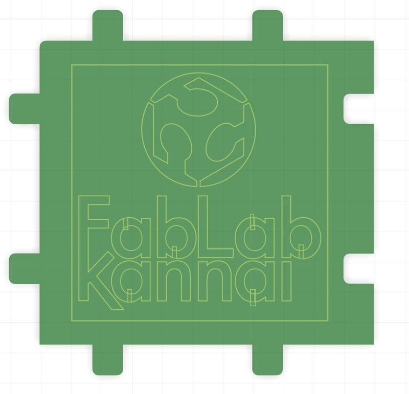
Since we want to put a new design on the lid, we erase the original design. 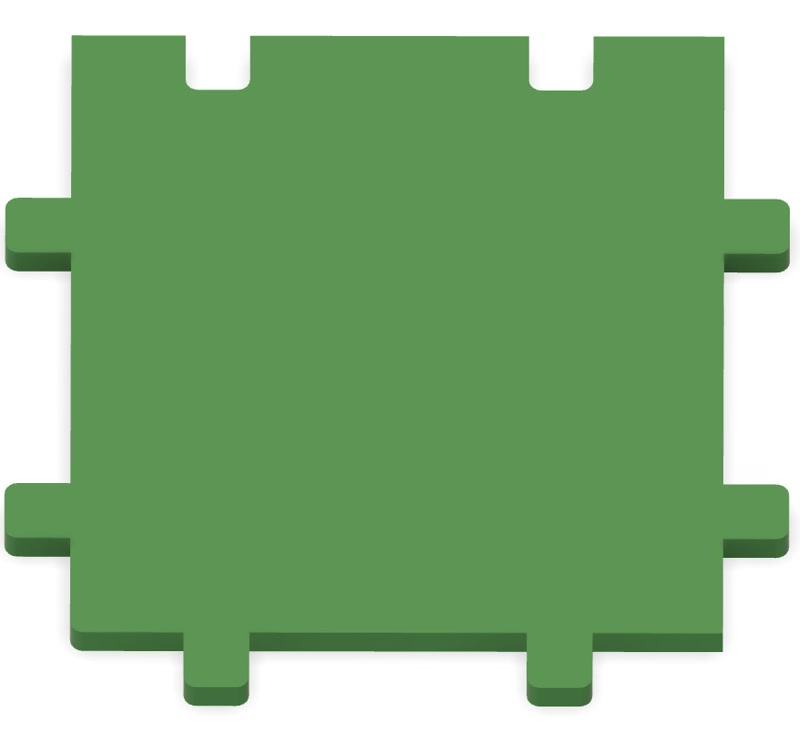
To insert the Fablab Kannai logo design into the lid, insert the logo in svg format into the lid and cut out the logo shape by extrusion.

Outputted svg file

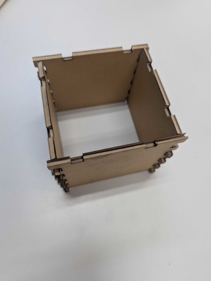
Assembly3
I reassembled it in a different way, using the modified lid parts cut out with the laser cutter. This time, it was assembled perfectly!
3D model
The 3D models we created are as follows.
3D model Download
Vinylcutter
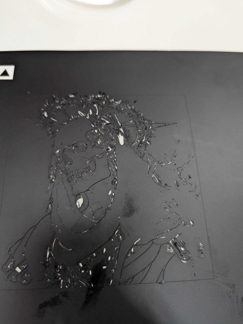
I made the stickers using the Silhouette Curio 2 vinyl cutter, and then used the stickers to create a sandblasted pattern on a glass cup.
Design creation
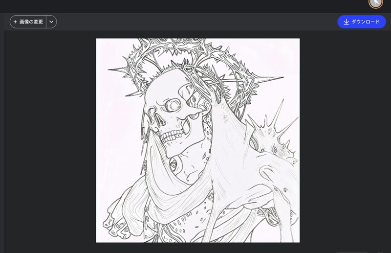
I will convert the logo image created in the previous assignment into a line drawing using the fotor service.
Cutting the mask
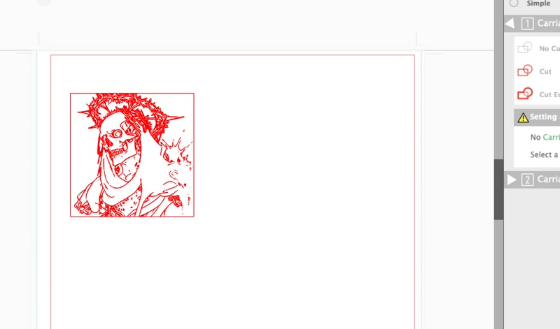
- Convert the file format to DXF format using Illustrator.
- Install Silhouette Studio.
- Import the DXF file into Silhouette Studio.
- Fix the vinyl sticker in place using masking tape.
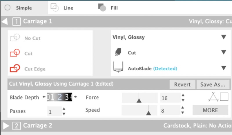
- Cut a small piece off the corner and test the parameters (in this case, blade depth: 2, power: 14, speed: 8)
- Start cutting the vinyl sticker.
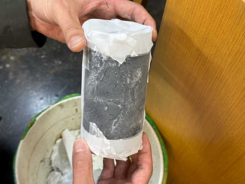
Attaching the mask
- Attach the cut-out mask to the glass cup.
- Press firmly to prevent air bubbles.
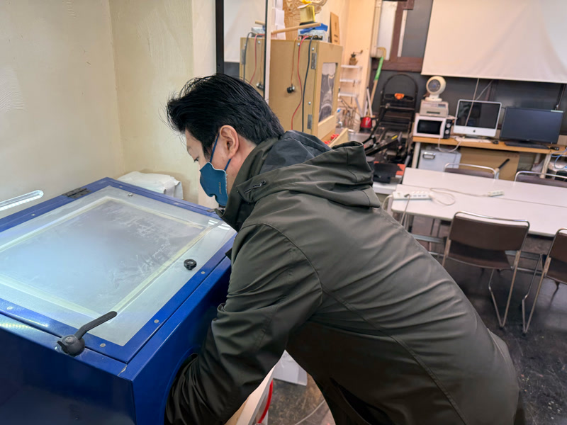
Sandblasting
- Set the glass cup with the mask attached in the sandblasting machine.
- Turn on the sandblasting machine and blow sand onto the design area.
- To create a uniform pattern, maintain a fixed distance and angle while sandblasting.
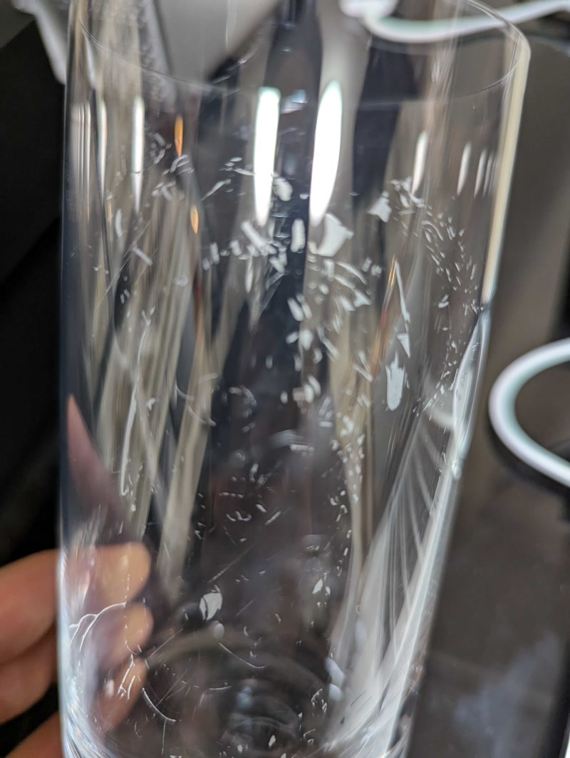
Removing the mask
- After sandblasting is complete, carefully peel off the mask from the glass cup
- If any adhesive remains on the mask, remove it with alcohol or a special cleaner
The lines in the original illustration were too thin, so I couldn't draw the lines very well using the sandblasting.
Design file
This is a design file for a sandblasting mask.
DXF file Download
Afterthoughts
In parametric construction, it was difficult to design the product while taking into account the kerf, joint clearance and cardboard thickness.
The lines of the sandblasting rough draft illustration were too thin, which was a mistake, but I was very happy with the sandblasting, so I'm satisfied!