3D Scanning and Printing
Group Assignment
- Test the design rules for your 3D printer(s).
Individual Assignment
- Design and 3D print an object (small, few cm3, limited by printer time) that could not be made subtractively.
- 3D scan an object (and optionally print it).
This week was pretty fun. I tried 3D print some piece I designed and 3D scanned!
Introduction
In this week’s assignment, I explored 3D printing and scanning processes to
print a custom-designed lamp inspired by a
Pinterest
Model.
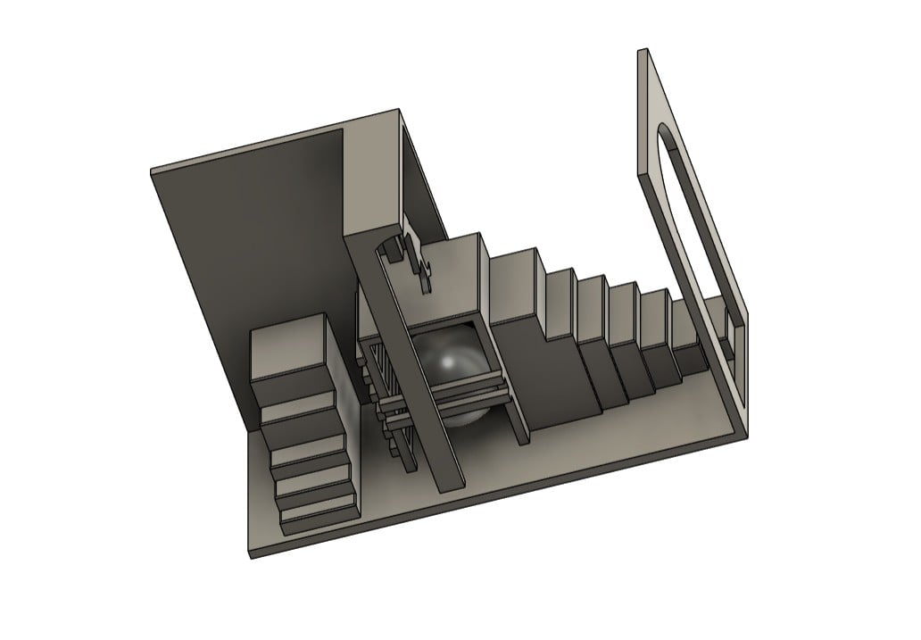
In order to make sure that my design can't be manufactured subtractively, I decided to add
underneath the figurine a cavity, where I inserted a sphere and enclosed it from the sides to
add complexity to the design.
In my opinion, it gives the illusion that this figurine is standing on a spherical pedestal that
is surrounded by prison-like grid, improving the visual appearance of the lamp and it is up to
the viewer whether to interpret it as empowering and freeing or restricting and limiting!
3D Designing My Lamp
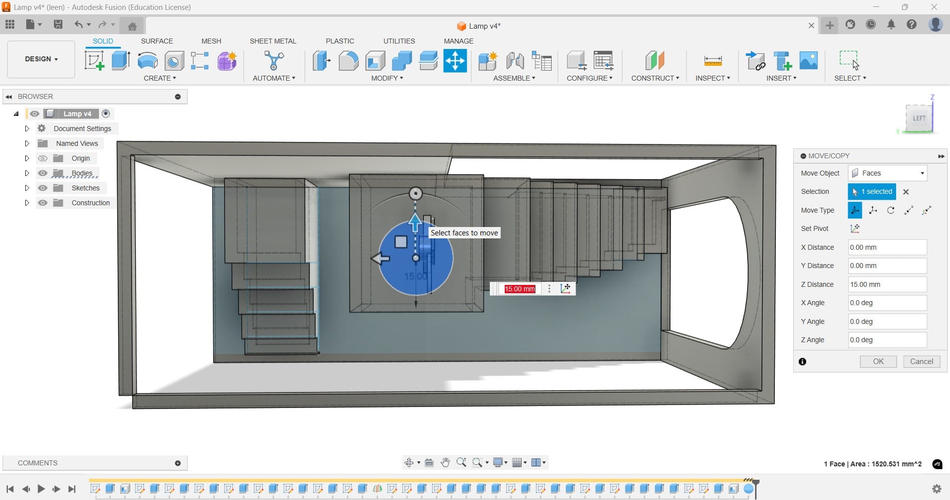
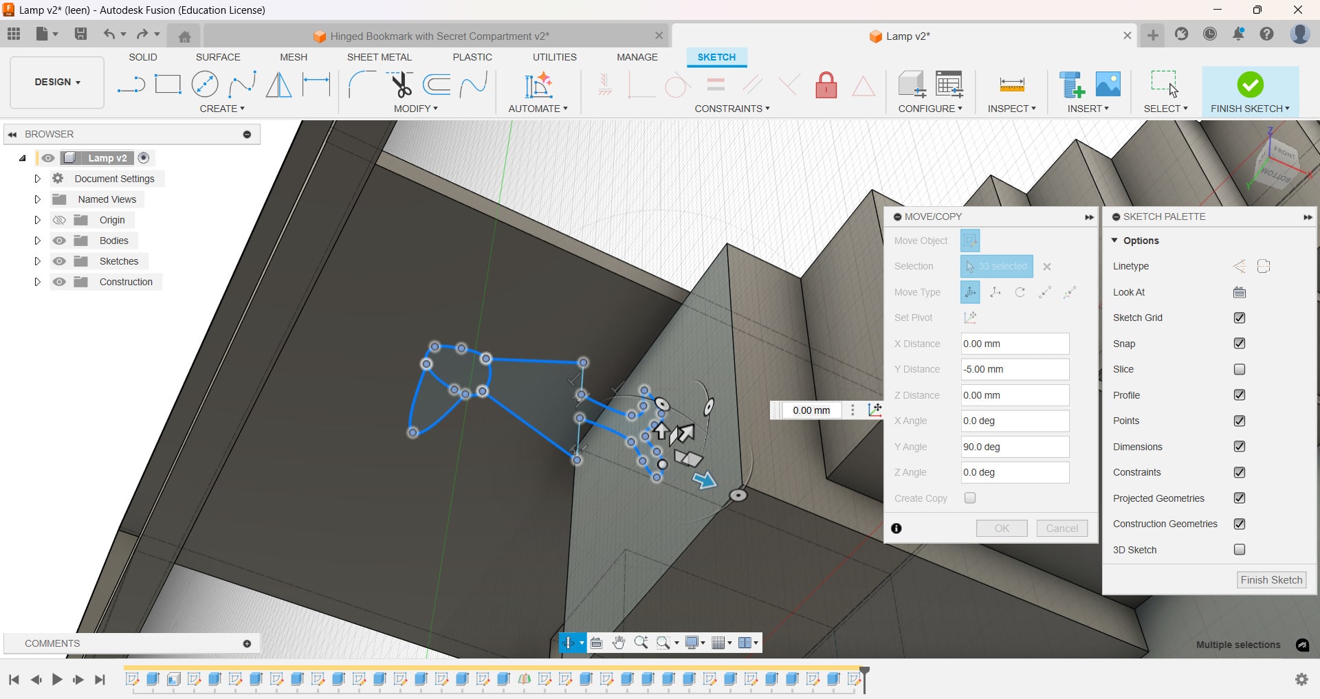
I learned new skills like adding Sphere, manipulating using the
move and rotate
functions to make sure it is inside the box.
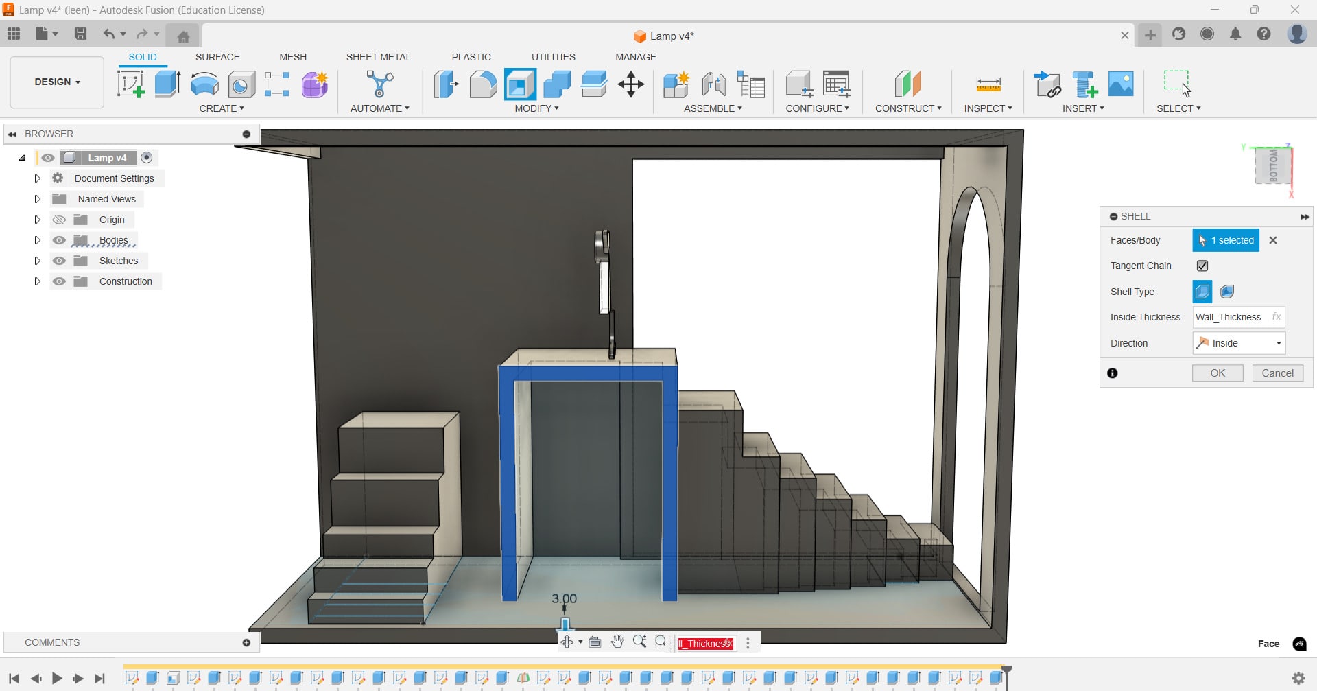
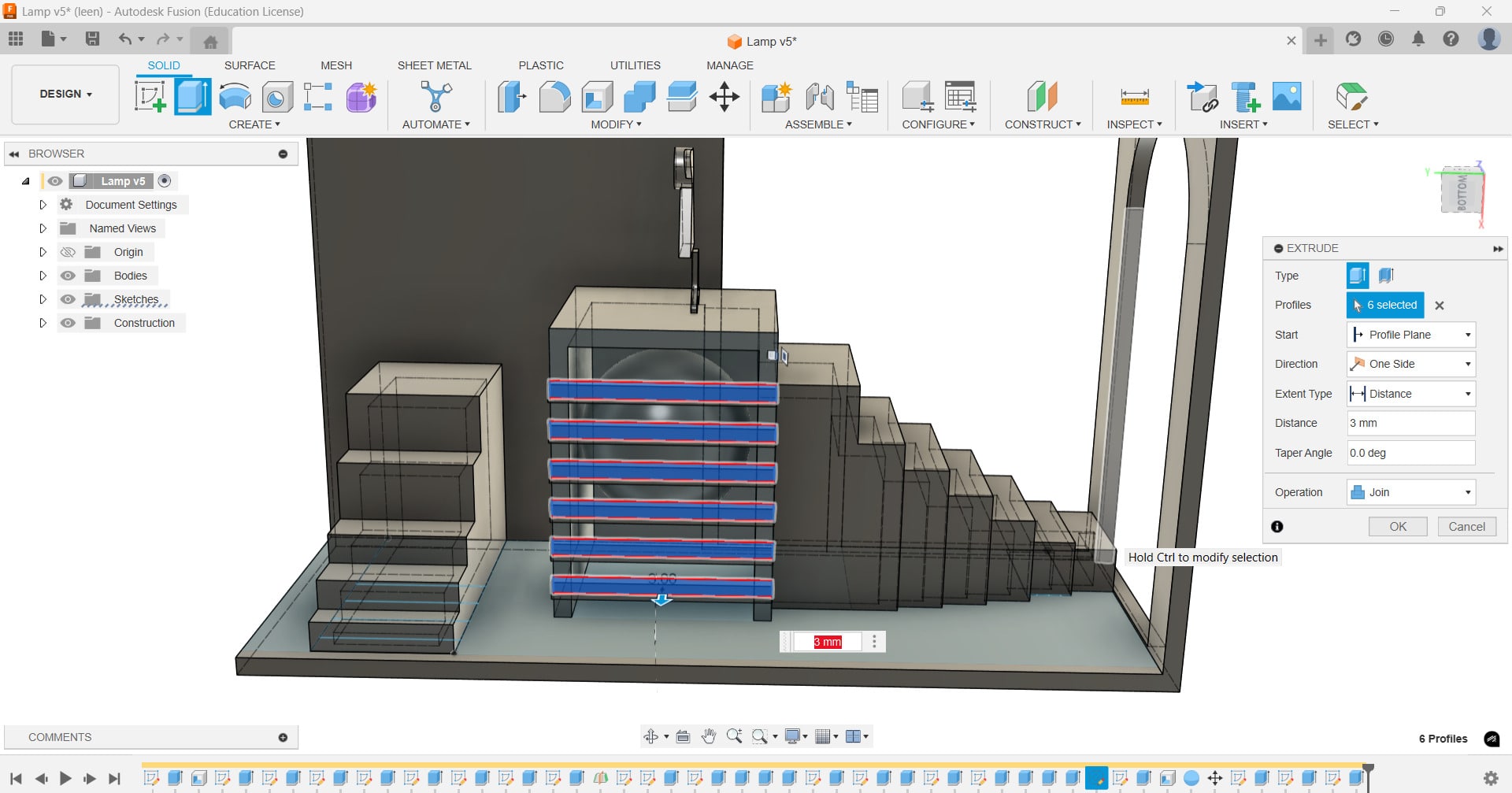
To make the design a little bit more complicated, I decided to add grid-like structure that
encloses
the sphere box, with leaving some gaps in between for visibility. This enables me to put the
claimed
advantages of 3D printing into test, namely making more complicated shapes and cavities in the
design.
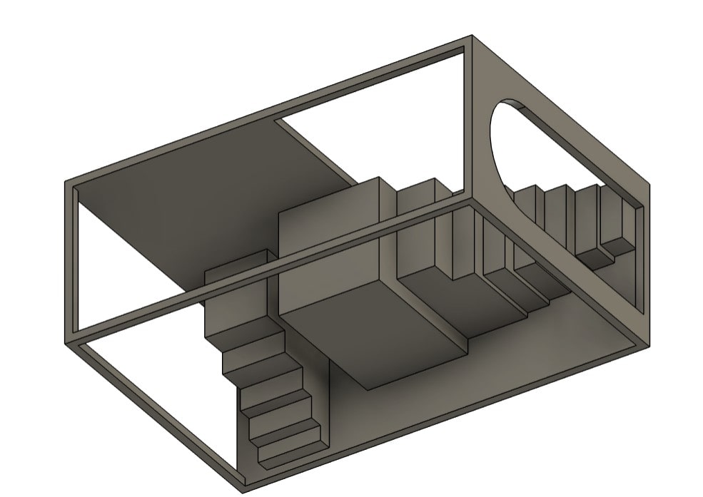
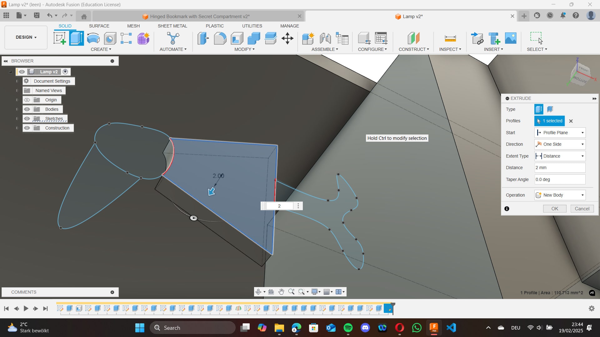
Other functions I already used like extrude for cutting and joining walls and
stairs
together, also adding arcs into my designing by extruding half squares together with rectangles
on
each side to form this Arch door entrance. It was quite fun.
I also added a little figurine by using the spline tool and drew it on the
plane,
then rotated it 90° to appear like it is standing on the platform.
To form the arch ceiling, behind it, I added an Offset Plane right behind the
figurine
to sketch another arch on it and created the 3D illusion.
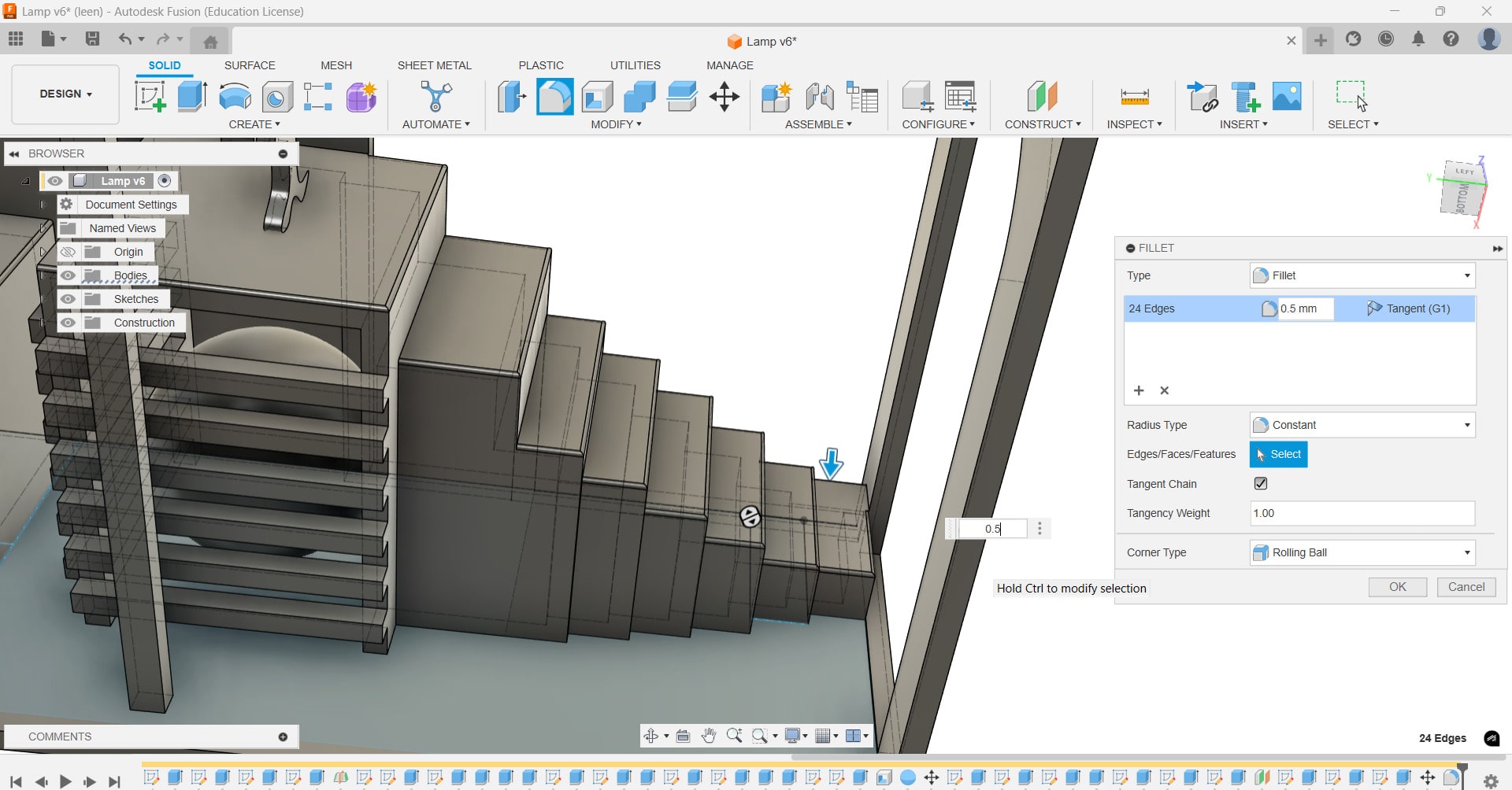
For visual effects, I added Fillet to the arch and Chamfer
onto the
stairs to smoothen them out. The overall piece was 150 mm long, 100 mm wide, and 60 mm high.
Final Lamp Design
Note: For basic functions I attempted, you can check
Week 2 - Computer-Aided Design.
3D printing my Lamp
After exporting my design as .STL file, I installed
Ultimaker Cura
5.8.1
and I opened my saved file.
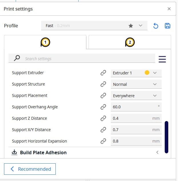
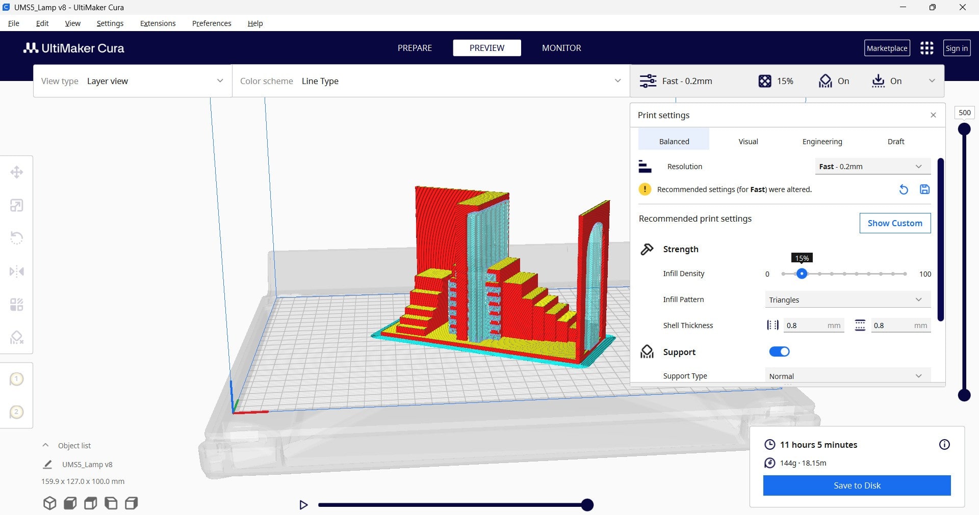
To set the setting, I selected material to Generic PLA 0.4 AA, the infill density to 15%. and
infill type
to triangle. In order to make sure my object does not have any overhang or sagging, I ticked the
option
for "support". For the support structure, I selected Normal and the placement
to
everywhere and the support z distance to 0.4mm.
These settings were expected to require a lot of post processing, but I did not want to change
my
design so I had to take responsibility for my decision.
After slicing, it stated that the print will need 11 h 5 min.
Then I fed the file into the printer, specifically Ultimaker S5. I just had to start it by pressing "start print".
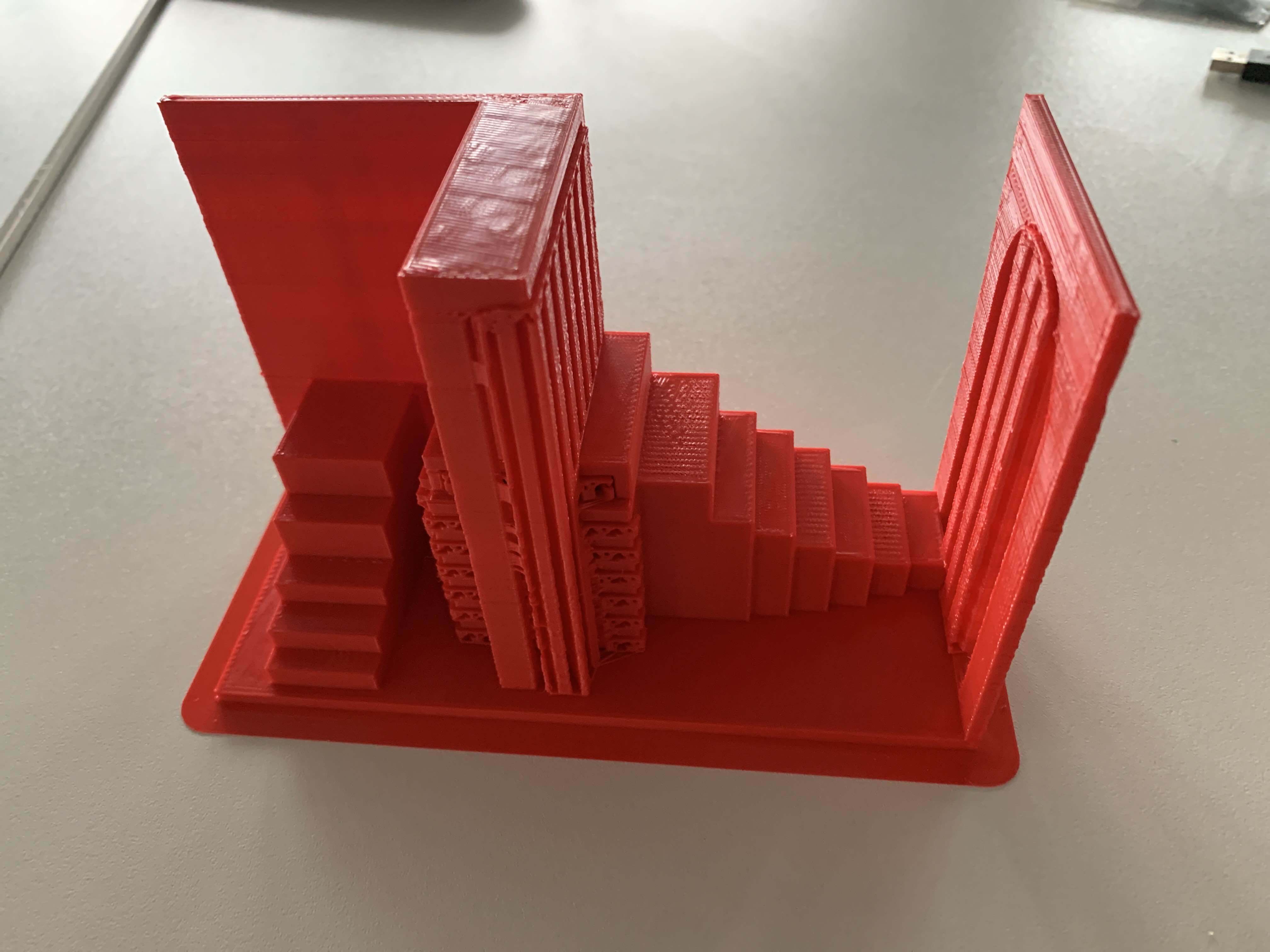
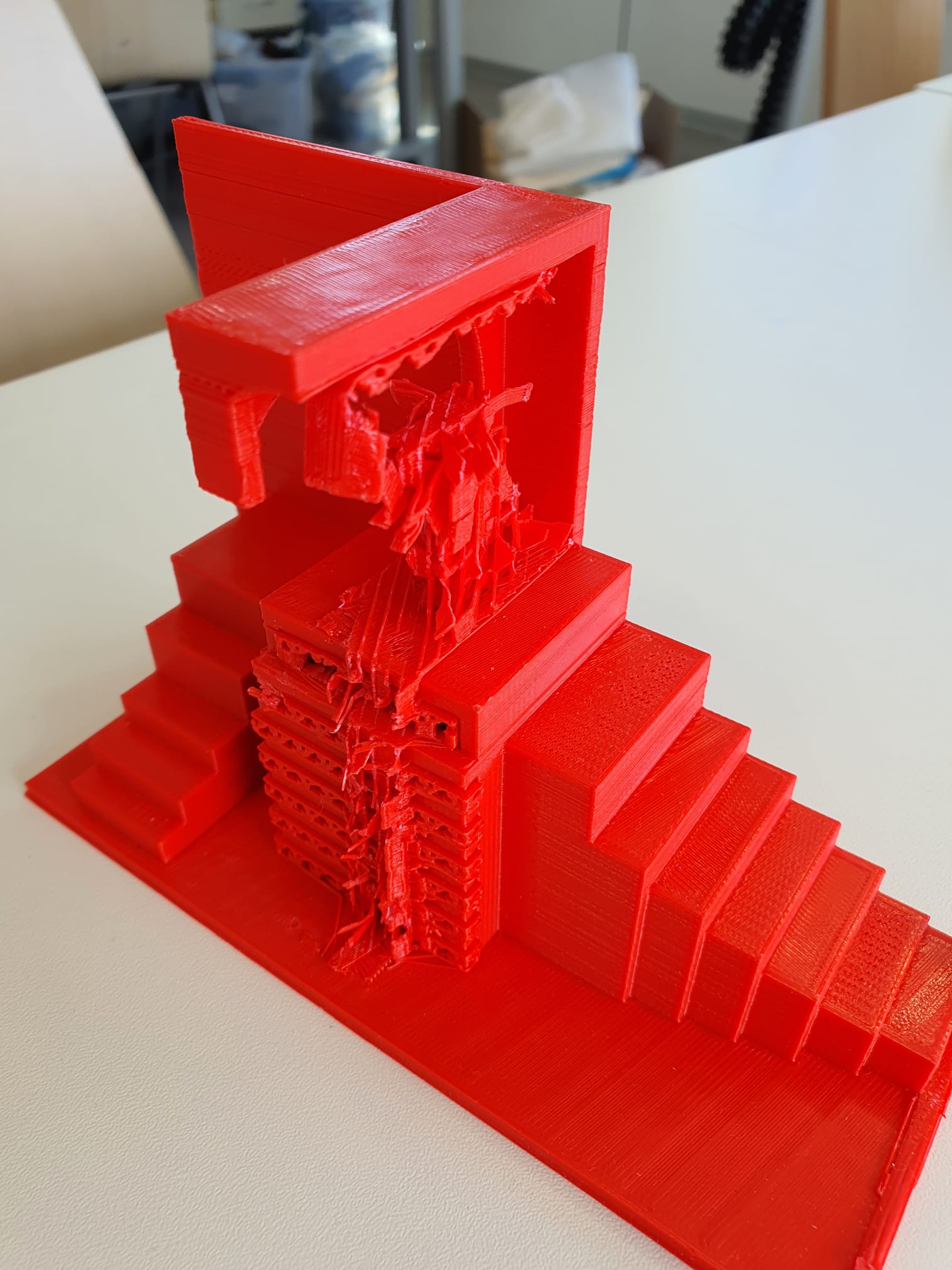
Print before removing Support Material
Reflection: Removing Support Material Failure
With the normal type support, the material could not be removed at all without breaking pieces
apart. Due to the print settings, namely the support gap (distance between the object and the
support material)
and the density of the support material added, it was almost impossible to remove the support
material without
damaging the object itself.
Since it was my first complicated design experience, I wanted to test printing with support
material with the
ultimaker. Although my local instructor Ahmed mentioned to me that with the ultimaker, removing
the normal
support material is very tricky and difficult, I wanted to test it myself and learn from my own
mistakes.
Moreover, due to the lengthy print time of the full sized design with the support material, I
had to deal with
the time pressure and improvise a simple alternative to fulfill the requirements of my
assignment.
Therefore, I decided to scale down my design and try with a different 3D printer and a different
support
type.
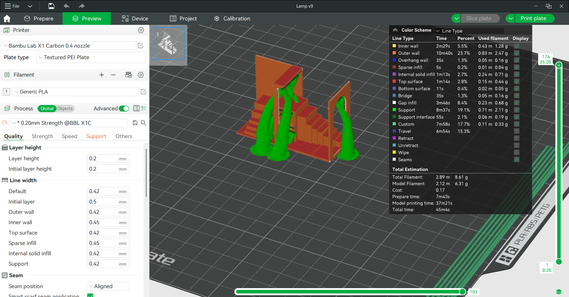
Second Lamp Print Attempt Process
I decided to give it a shot with the organic support type
using the Bambulab that
Lysander characterized.
Furthermore, I reduced the scale down to 35%, so it is
significantly less time and material costly.
After slicing, it took roughly 45 min to print!
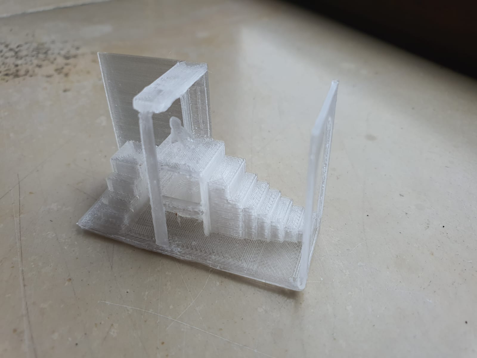
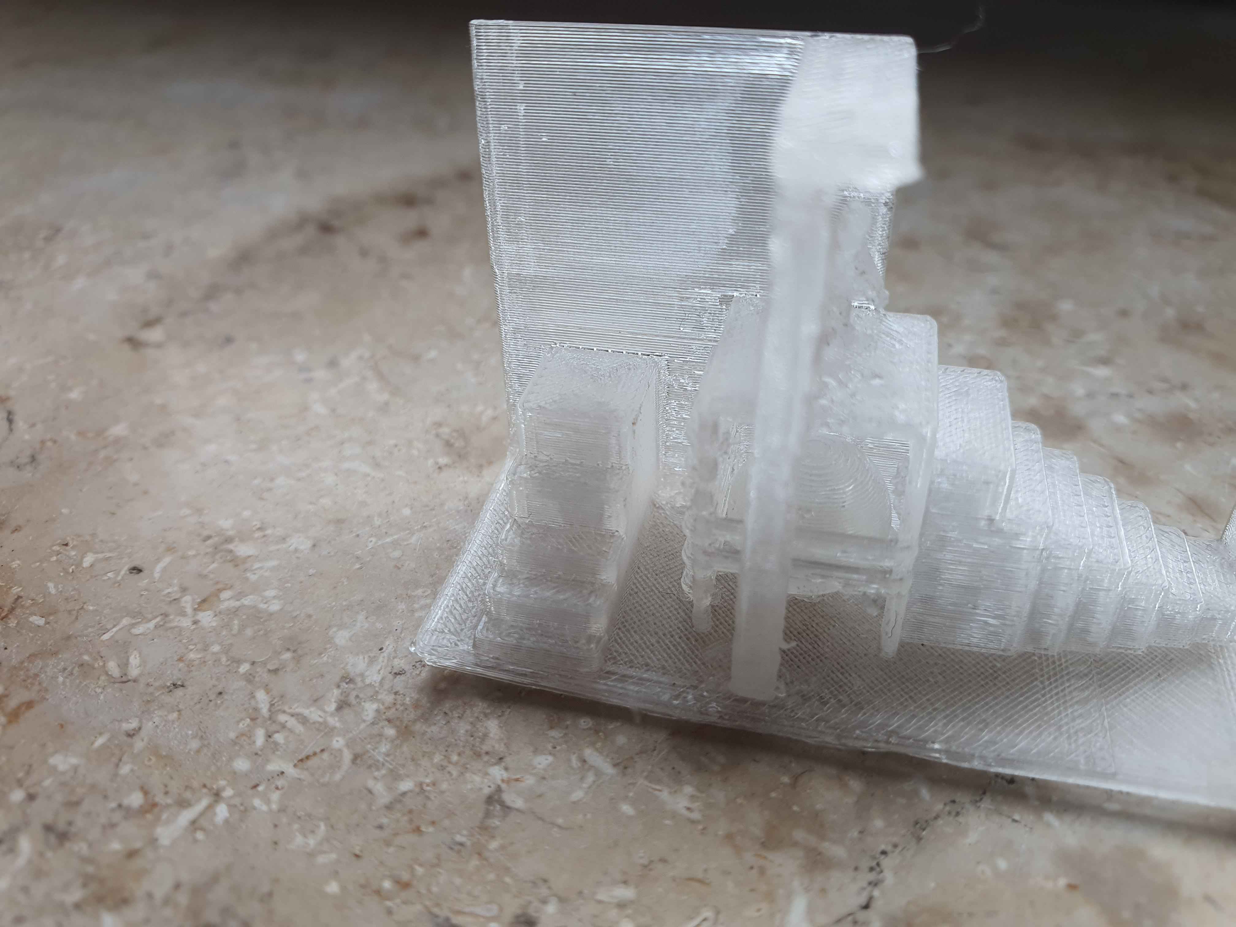
Second Lamp Print Attempt Result
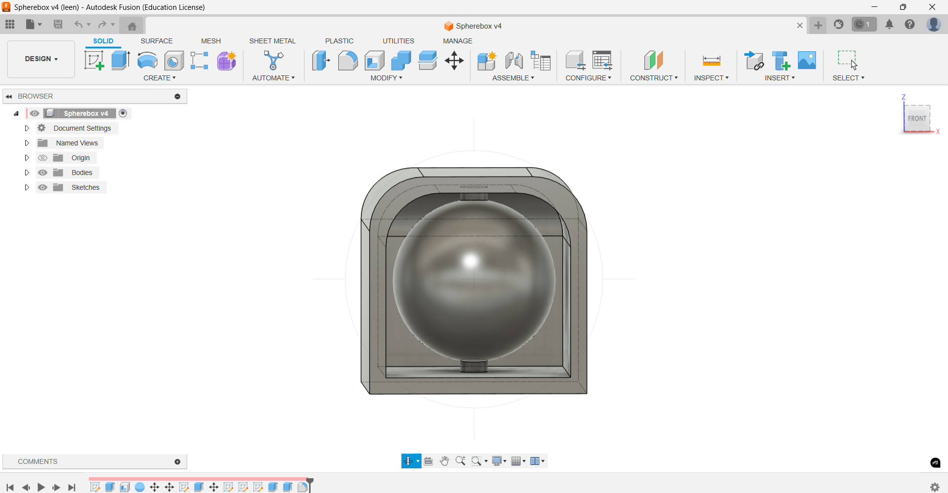
Third Experiment: 3D printing the Lamp's Inner Box with the Sphere
Since printing my lamp was not a very successful practice using the ultimaker normal support
setting, I designed the box with the sphere inside and I added a pipe going
through the center of the sphere by sketching a circle at the bottom surface of the cube and
extruding it from top to bottom of the cube, and set the operation to join, so
the support is technically not needed.
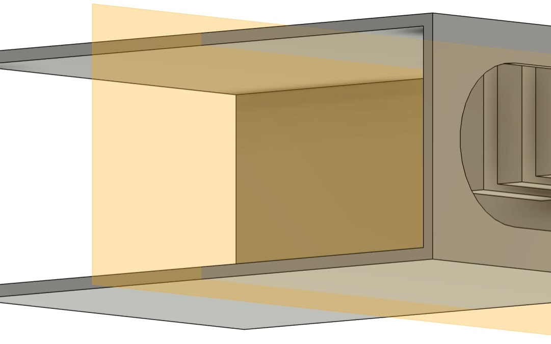
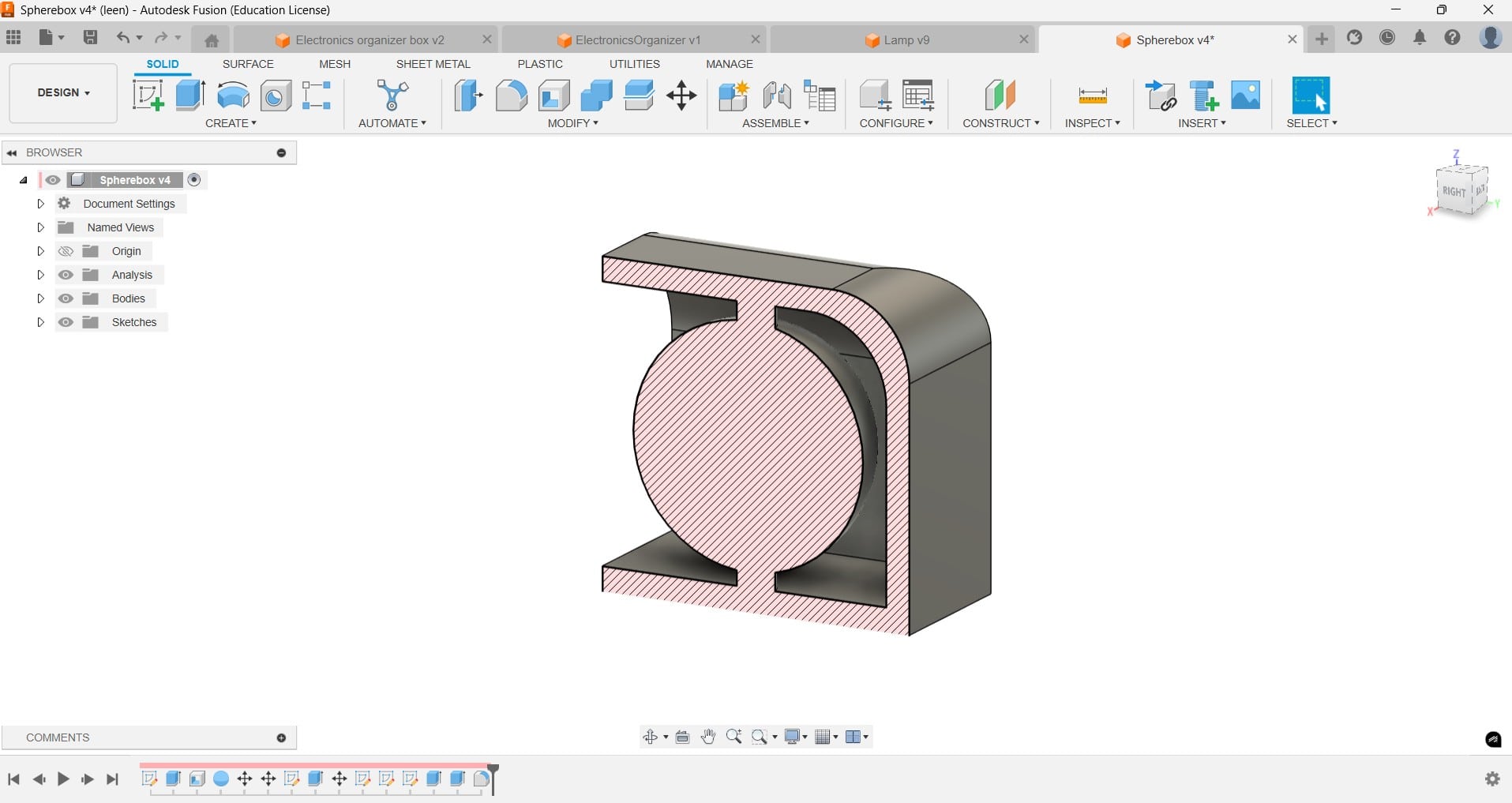
Why Subtractive Manufacturing Won't Work?
Looking at the cross-section analysis, the geometry of the sphere inside the housing makes it
hard for any CNC machine that is not multi-axis to manufacture!
The machine needs to access the area inside the housing and remove the extra material between
the ball and the inner wall of the curve. Unlike additive manufacturing, which allows forming
cavities or partially enclosed geometries without complicated toolpaths.
See Week 7 - Computer-controlled Machining
(Subtractive Manufacturing) for further input on CNC Machining.
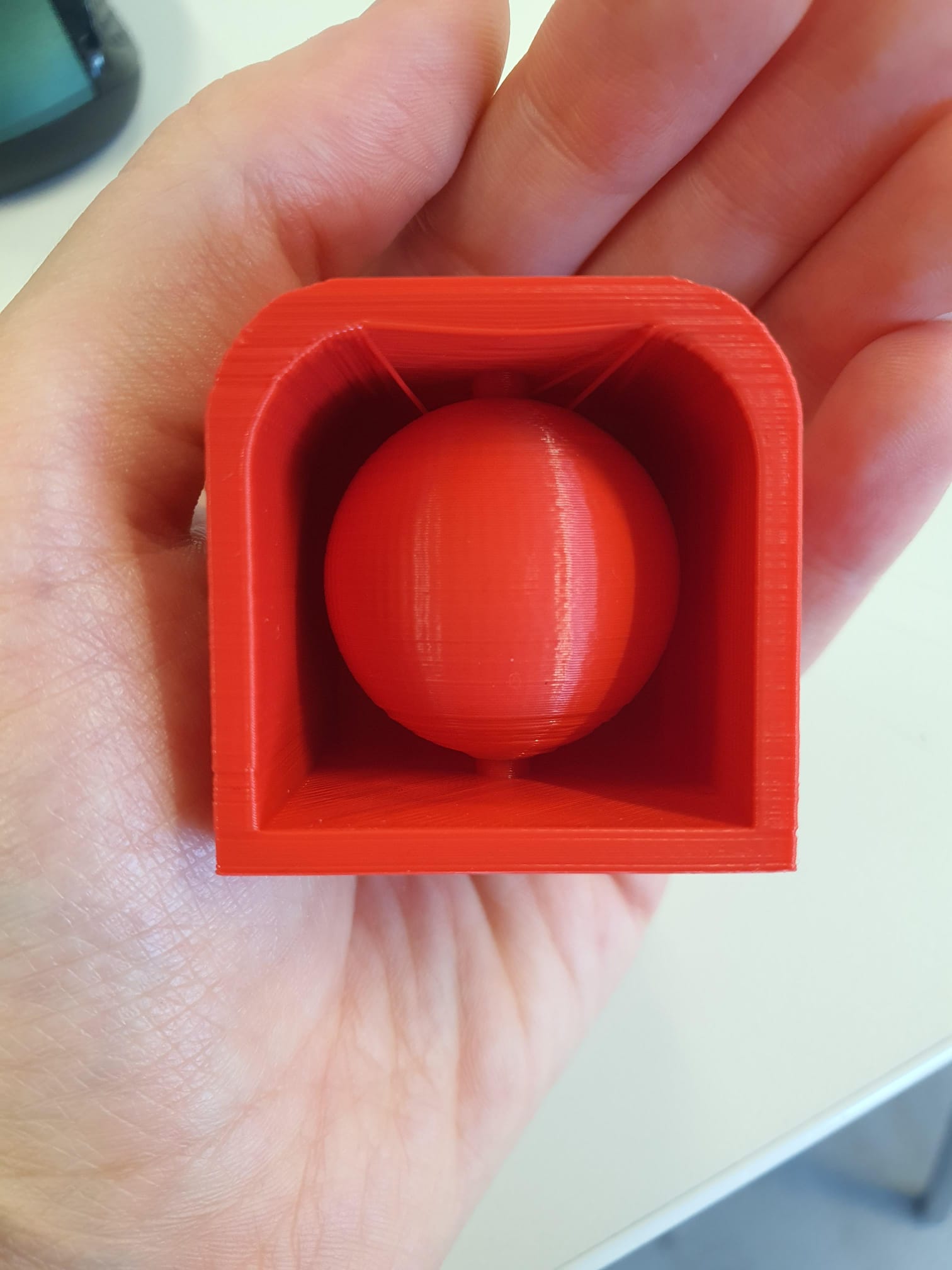
Why Support Material was not Needed?
The print turned out very well! You can see because of the borderline bridging with the pipe
going through the ball and the short distance (~2.7 mm) between the ball and the inner roof of
the cube, no support material was needed!
Moreover, the overhang of the ball (angle <= 30°) relative to the horizontal line helped prevent
a spaghetti-like structure from hanging underneath.
Reflection
Subtractive manufacturing principle is based on removing material from a solid block,
which limits it to objects that the cutting tools can easily reach.
In my lamp design, there are many intricate details—like the curved arches, and internal
cavity with the sphere inside—which makes it challenging for CNC machine to make it
accurately.
In the case of 3D printing (additive manufacturing), the piece is built layer by layer,
which allows creating delicate figures, without the constraints of tool access or the
large amounts of material waste like in subtractive methods.
3D Scanning
For this task, I decided to 3D scan my teammate
Mika's Week 5 and vice versa, so we helped each other!
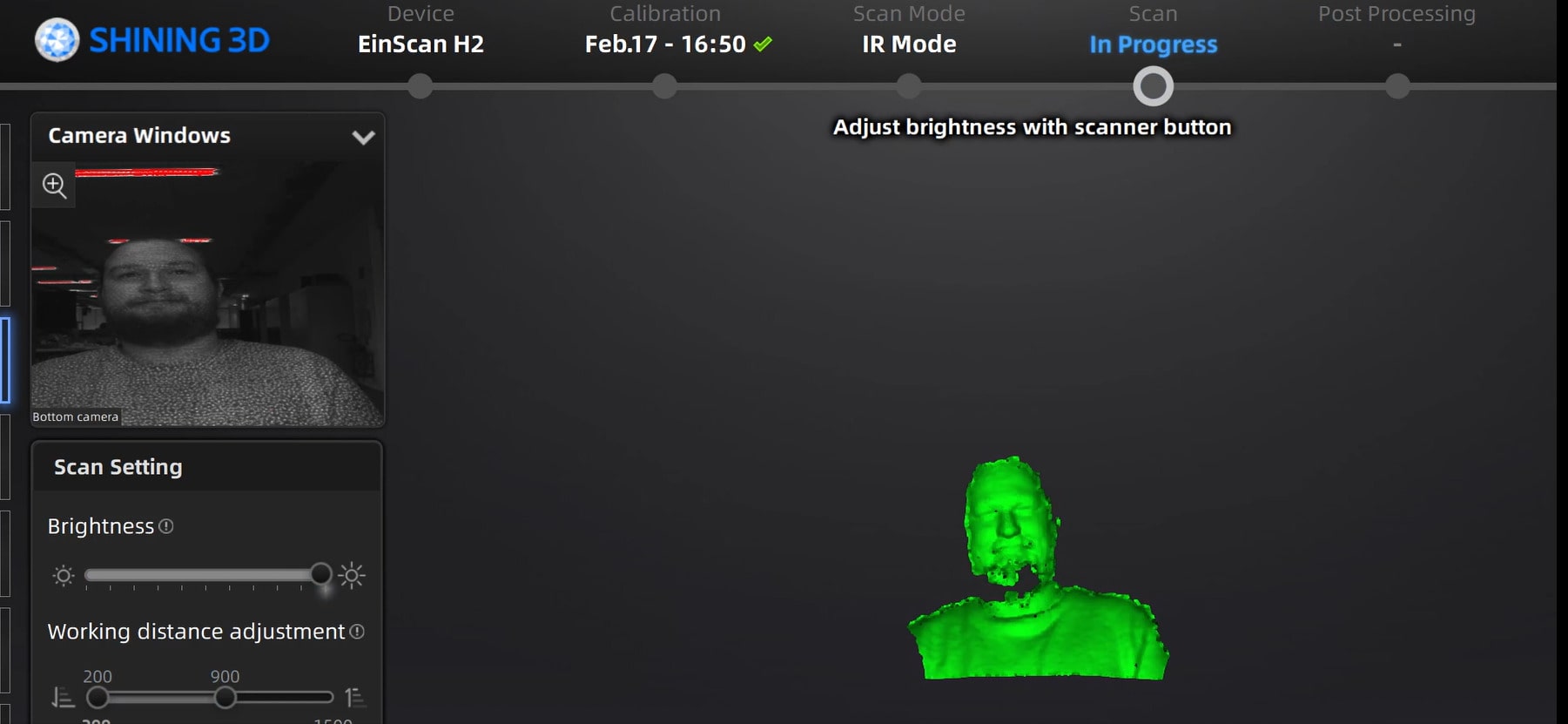
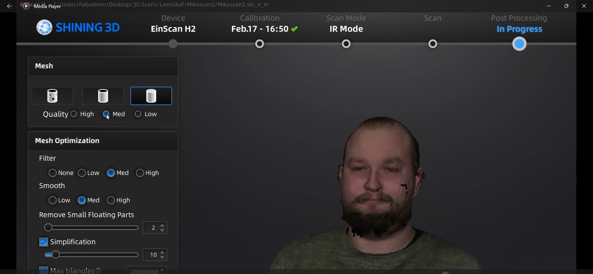
For calibrating and setting scanning parameters, I used
Shining 3D.
After we calibrated
EinScan H2, which is a scanner primarily used to scan human
bodies,
I started setting the parameters for the scanning progress.
I selected the scan mode to be "IR Mode". Then, I created a new project folder and named
it
"MikaScan". Scan Target was set to "Portrait", the alignment to be "hybrid", resolution
to be
"medium".
Afterwards, I started slowly with the machine scanning all angles
trying to get as clean of a scan as possible. Finally, I pressed done and manipulated
the scan in the software. I removed random points. After being satisfied with the
result, I carried on with "optimizing and generating point clouds". This is done by
the software to try and patch missing points from the scan.

Then, for meshing I set the mesh quality, filter, and smooth to "medium".
Lastly, I saved the files in all types (.stl, .obj, .ply, .mdf), and
I scaled down the size to 30%. These files could be used for further processing
in case Mika wants to 3D print a miniature version of himself :D.
3D printing my Miniature Scan
After Mika scanned me and the mesh turned out to be very good, I was curious to 3D print
the result!
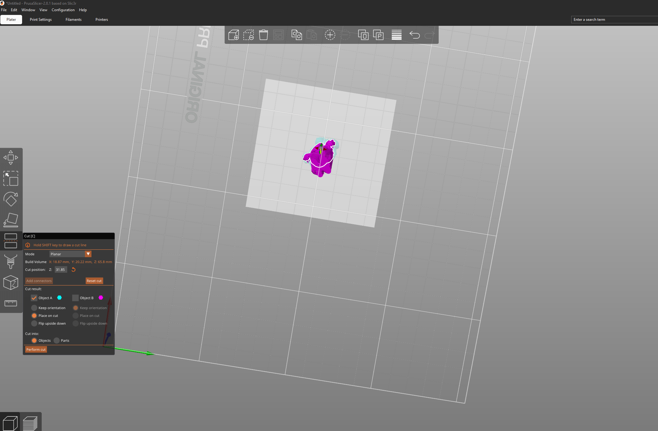
For processing, I used PrusaSlicer
and MeshMixer.
For the print to be stable, I designed a small square base using Fusion360 and exported
it as .stl file. Then, on Prusa, I opened my scan and tried to manipulate it, making
sure
that the bottom surface of the feet is flat and leveled.
For this, I rotated the perspective 180°, used the function "place on face",
selected the bottom surface, then performed function "cut". The print was scaled down to
20%,
ending up with the dimensions of 67 × 21 × 17 mm.
Then, I saved the new version of the scan and reopened it in MeshMixer
to combine the base and the figurine into one .stl file.
First, I dragged and dropped both files. Then I went to Edit >
Transform in order to select the right coordinates for the figurine
to be placed right on top of the base.
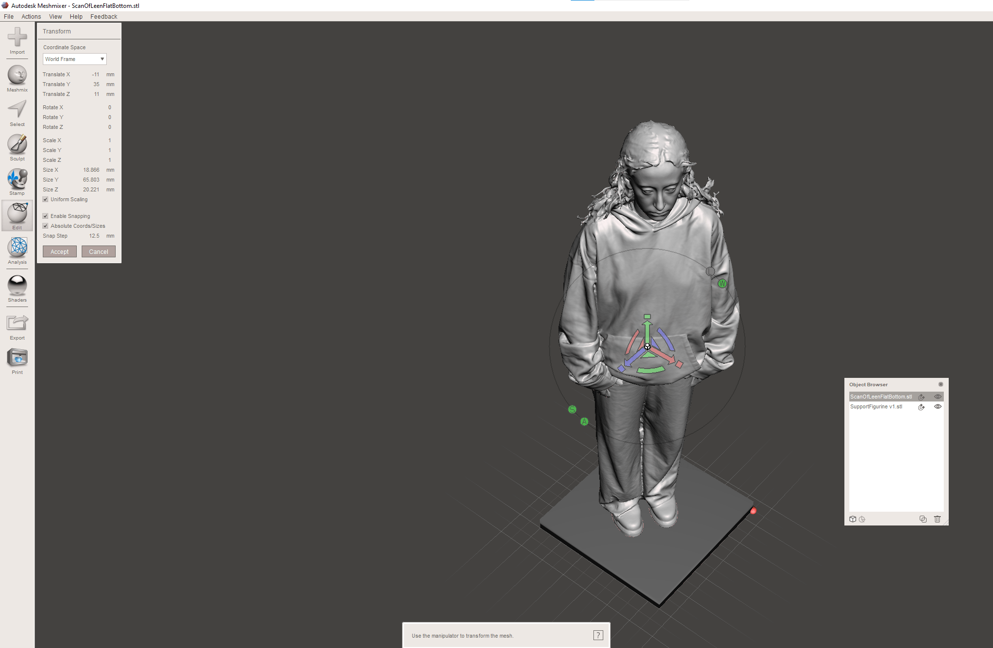
After placement was checked from every angle, both the base and the figurine
were combined using the combine function.
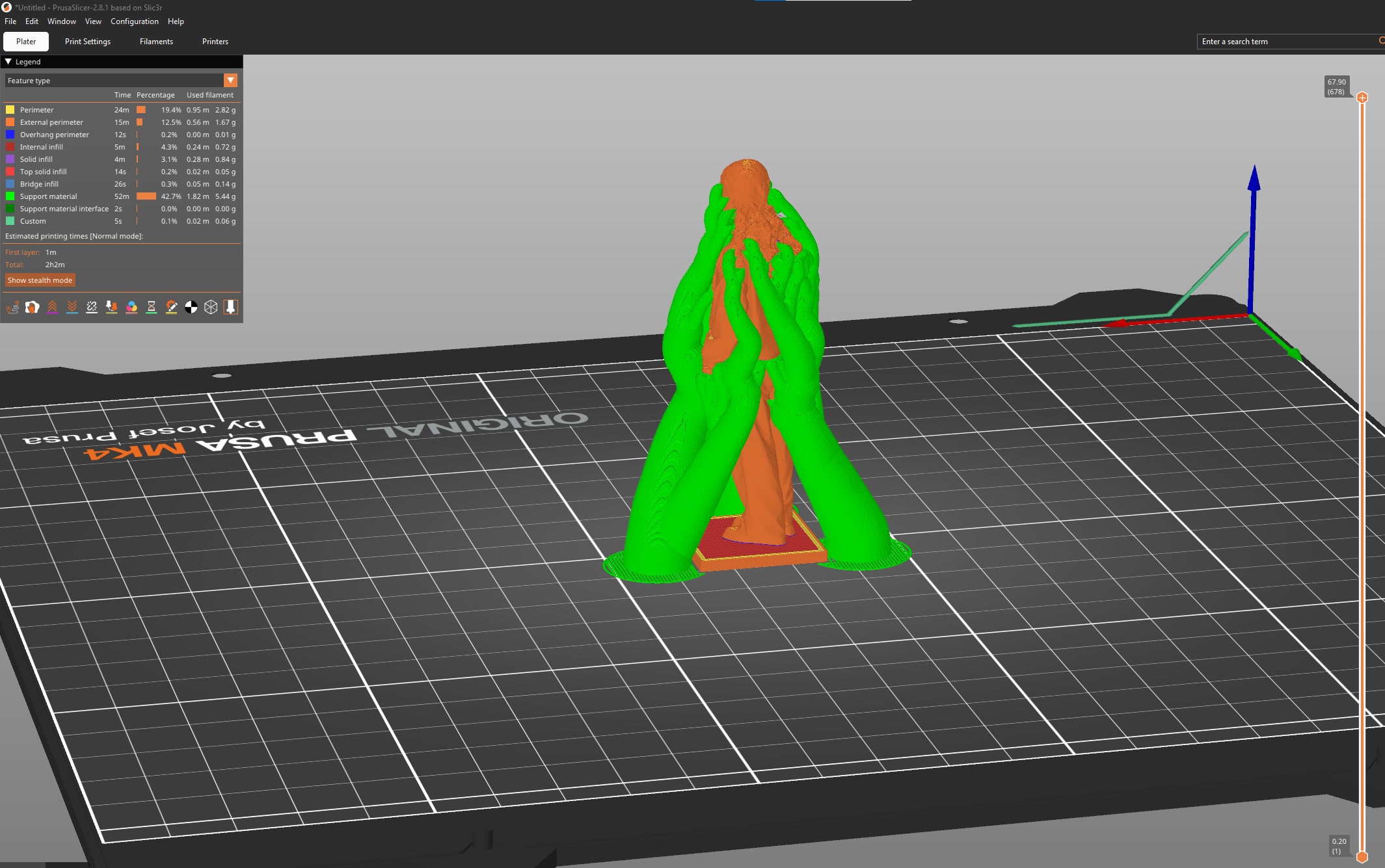
Finally, to set the printing setting, I went back to PrusaSlicer. First, I switched
from "Beginner" mode to "Expert" mode to be able to manipulate more settings.
Since I learned from my struggle with the normal support, I knew more confidentyl how to
approach the printing settings for my miniture!
Therefore, I went to "print setting" and ticked on
generate support material, set the style to organic,
and ticked on Support on build plate only.
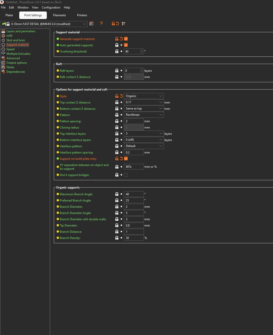
Finally, the print was ready for slicing. Printing time was 2 h 2 min.
Figurine Attaching .STL File Problem
While trying to upload the original mesh with 100% resolution, I hit the soft limit
for the GitLab repo storage (941 MB).
I reset my repository by cloning the old version from my repo locally, then adding
slowly from the fresher local version folder, pushing and committing step by step.
Now, only the STL file for the figurine was left.
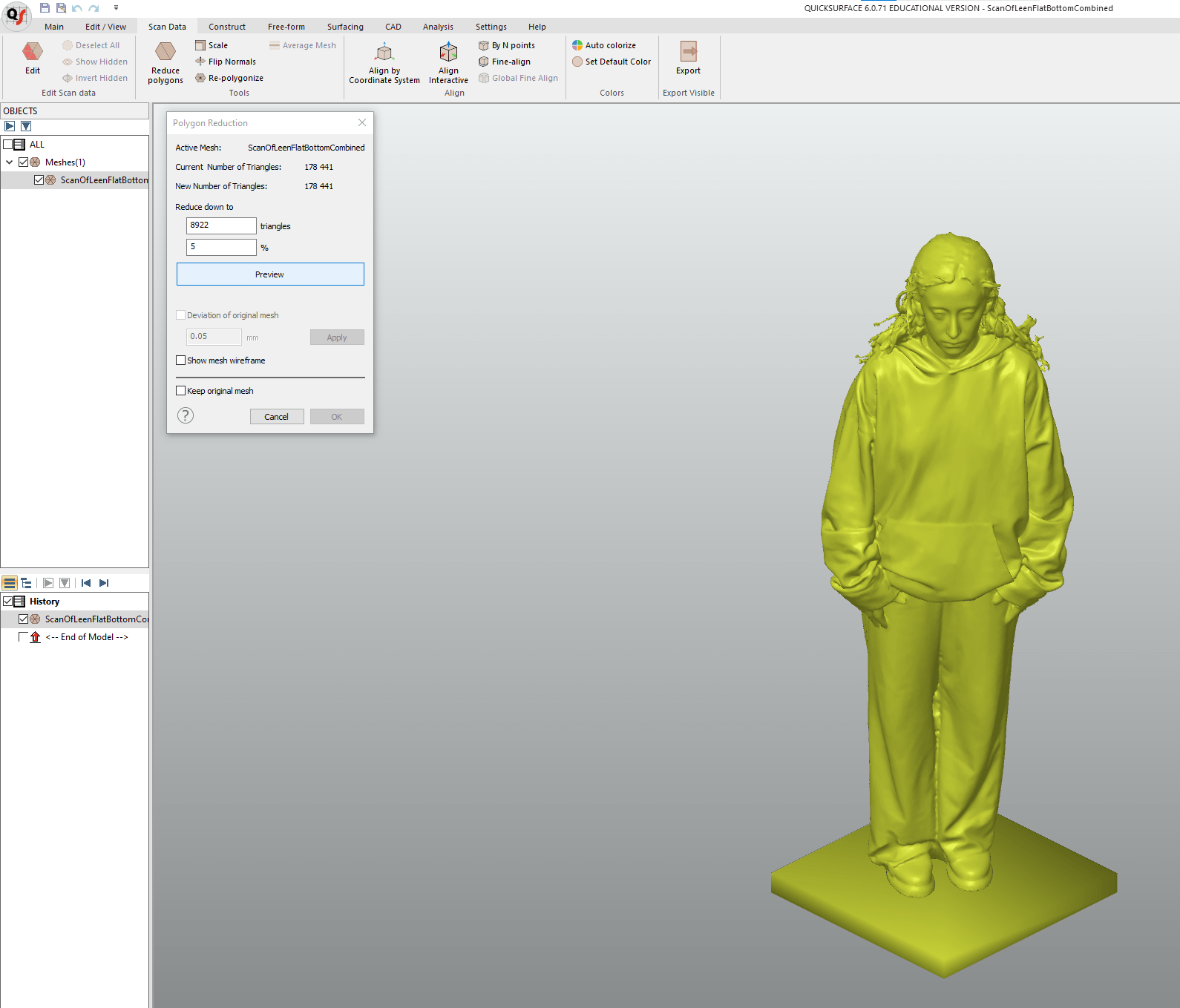
Therefore, I had to use QuickSurface to
reduce the mesh down to 5% (8.5 MB). The only downside is that it’s not open-source,
but we have it in the lab PCs so why not use it to serve the purpose!
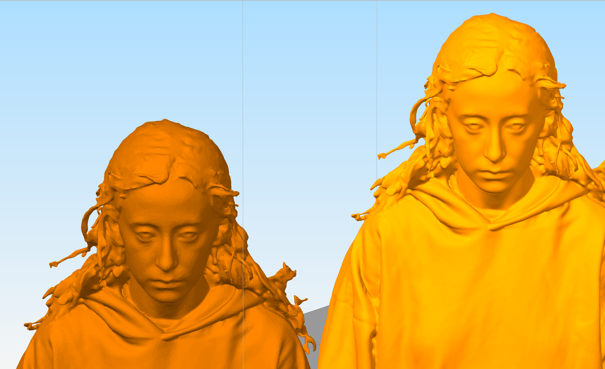
For comparison between the old and new mesh, I opened both STLs in
Slic3r. If we zoom in,
we see the triangles being more rough in the reduced version.
However, for 3D printing, the difference will not be visible.
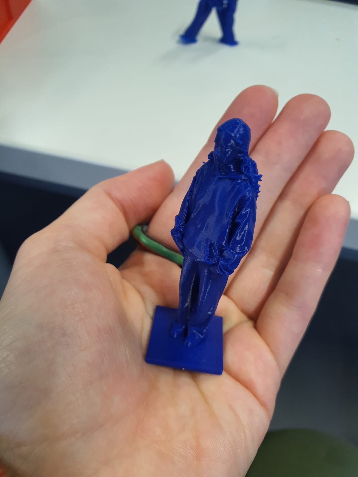
Leen Miniature before removing Support Material
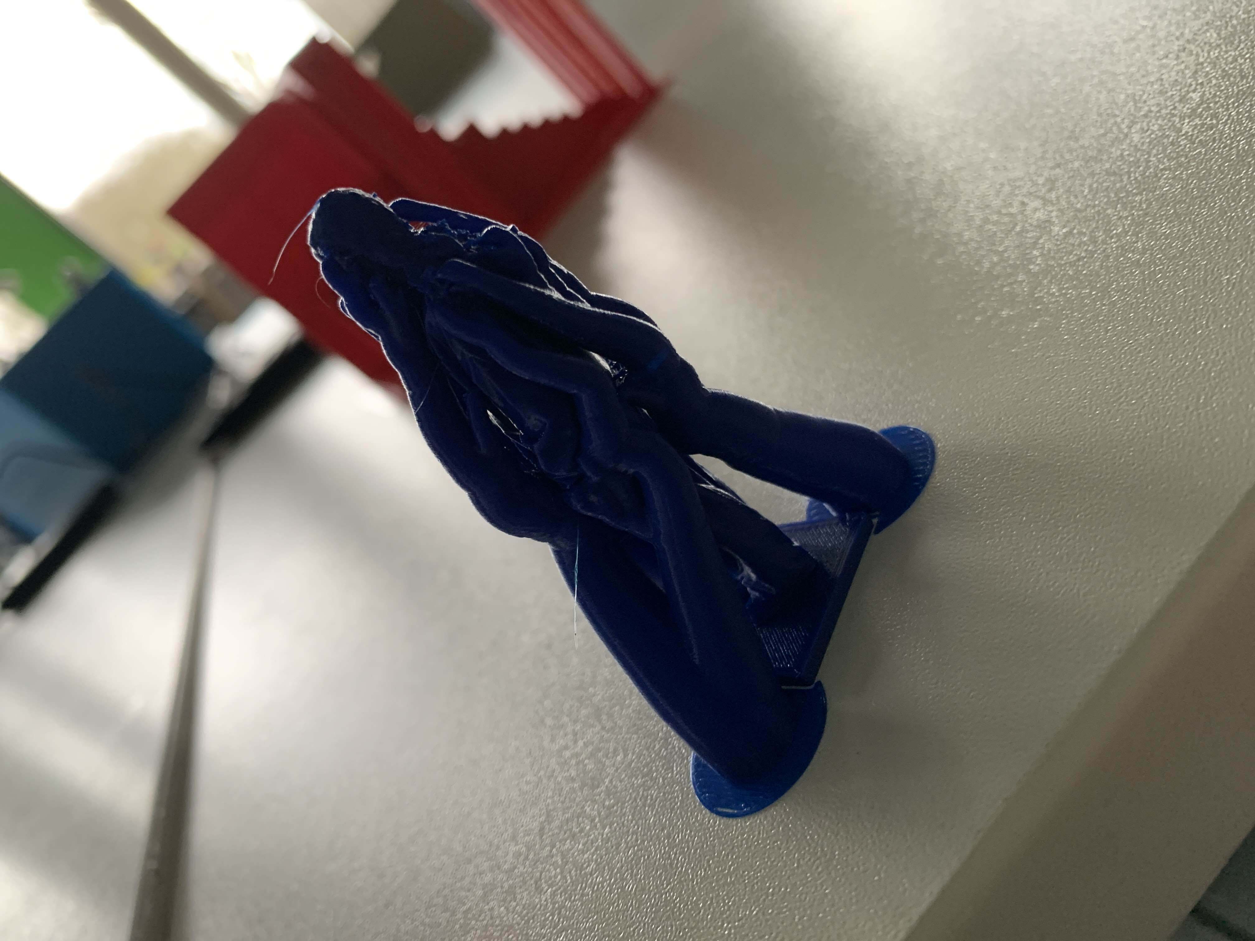
Leen Miniature Figurine after removing Support Material
All I can say is that it took a long time and maneuvering with pliers to remove
all the support material. I will try next time to have a design that requires less
support!
Reflection: Advantages and Limitations of 3D Printing
Advantages: 3D printing offers design flexibility, which enables
printing of intricate geometries and complex structures that traditional subtractive
methods
cannot easily achieve. Additionally, it minimizes material waste by forming objects
layer
by layer and supports rapid prototyping.
Limitations: On the downside, 3D printing is often a slow process compared to other techniques such as laser cutting, and the printed objects often require post-processing. Additionally, the selection of filament depends on the mechanical properties of the printed objects that serve the function you desire!
Limitations: On the downside, 3D printing is often a slow process compared to other techniques such as laser cutting, and the printed objects often require post-processing. Additionally, the selection of filament depends on the mechanical properties of the printed objects that serve the function you desire!
Reference: Xometry. (n.d.). Subtractive vs. additive manufacturing.
From Link
Files
Figurine.3mf
Figurine.stl
SupportFigurine.f3d
Spherebox.f3d