Computer-Aided Design
- Model (raster, vector, 2D, 3D, render, animate, simulate, ...) a possible final project, compress your images and videos.
This week I started practing on different tools for 2D, 3D design, as well as compressing images and videos.
2D using Inkscape and GIMP
To create my animation, I used both Inkscape and GIMP. These were recommendations from a friend that did Fab Academy
back in 2021 Jeff's FabAcademy 2021.
Creating SVG frames for the animation
Creating a sprouting sapling animation involves drawing multiple frames
using Inkscape. I used the rectangle tool
to draw the soil using brown color, and the elipse/arc tool to draw, the seed, the roots, the
trunk and leaves. Each frame captures a slight growth of the sapling to create a smooth
animation. Eight frames in total were created and saved as .svg files.
Converting .SVG files to .PNG files
To convert all SVG frames of the sapling into PNG format using the
terminal, use the following command:
for file in *.svg; do inkscape "$file" --export-filename="${file%.svg}.png"; done
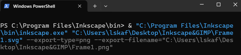
However, in my case, I had two different directories for the frames and for
Incscape, so I
had to work my way around it using the following command:
& "FullPath\to\directory\inkscape.exe" "FullPath\to\directory\Frame1.svg" --export-type=png --export-filename="path\to\directory\Frame1.png"
Creating the GIF
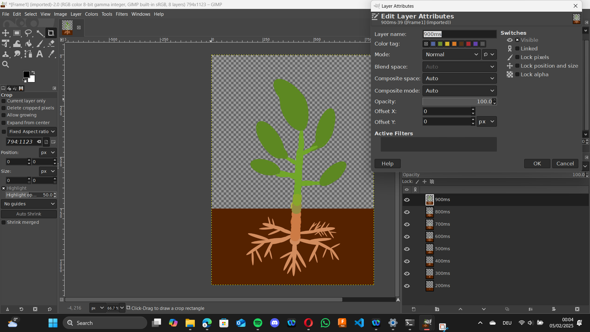
In GIMP,
the final animation is created by importing the PNG frames as layers. To ensure the layers
are arranged in the correct sequence, go to the Layers dialog, right-click
each layer and select Edit Layer Attributes and rename them based on the
time interval you would like to have between the frames (e.g. 200ms, 300ms,...etc).
Exporting the GIF
Optional: To preview the animation before export, go to
Filters > Animation > Playback.
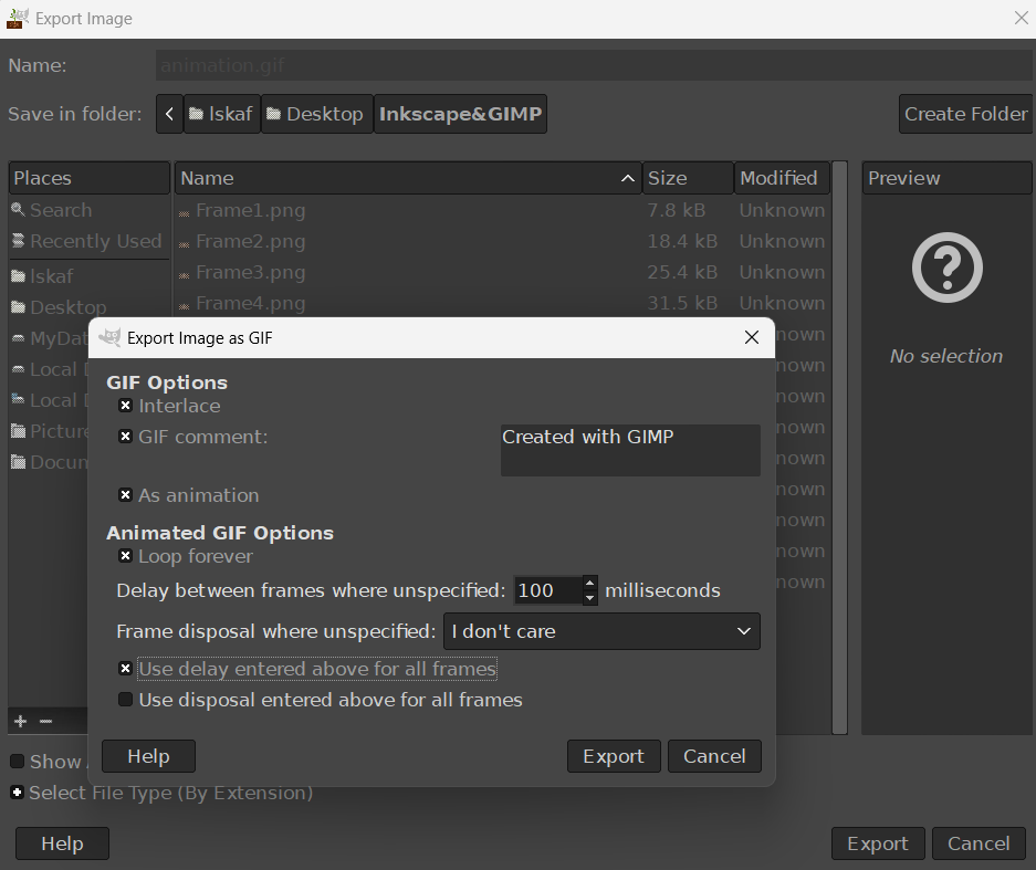
When exporting as a GIF, check the "As animation" option and
Interlace option if you want the GIF to appear progressively as it loads.
You can adjust the frame delay for smooth playback. In my case, I chose 100 ms.
Final Animation of the Sprouting Sapling
Finally, we have a beautiful sprouting sapling animation!

3D using Fusion360
For 3D modeling of the USB-ports case, I used Fusion360.USB Case Inspiration
Naming your Components
The 3D modeling process starts by creating a new component and
naming it appropriately. In my case, I named it "USB port case".
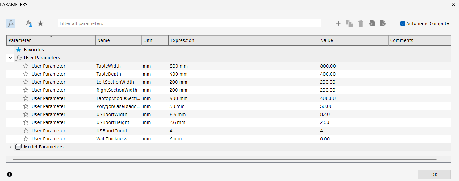
Parametric Design
Next, parameters are defined using Change Parameters tool
from
Modify menu to ensure precise dimensions for the USB-ports case.
Creating the USB-ports case sketch
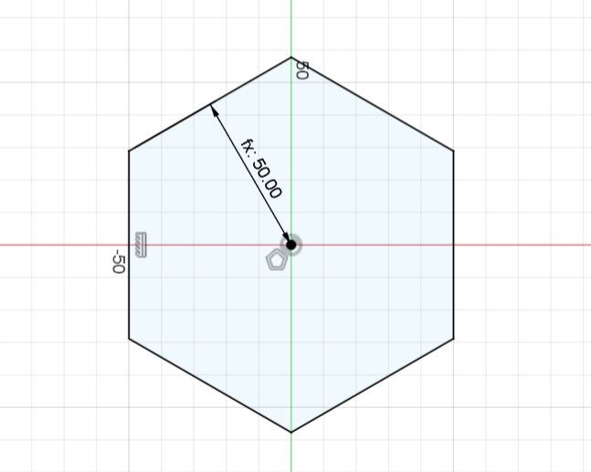
First, press Create Sketch icon. You will be
prompted to select your plane, select the XY plane. Then, from the Create menu, select
the Circumscribed Polygon tool to draw the main shape of the case. The
polygon's area is set based on the predefined parameter
"PolygonCaseDiagonal", in order to obtain an accurate base structure.
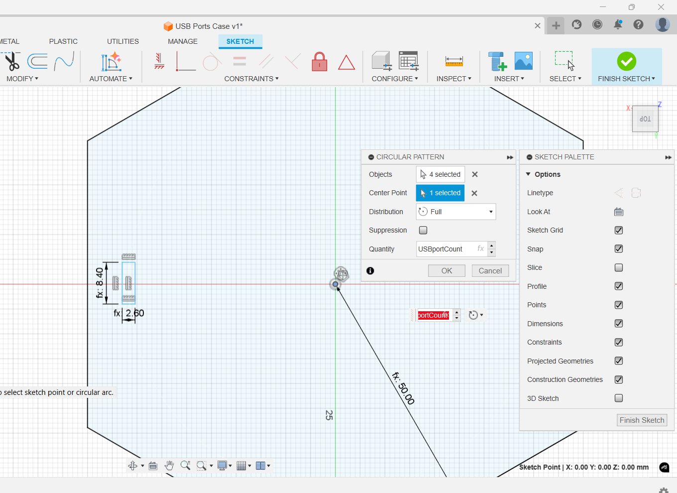
To create USB ports, I added one rectangle on one side of the hexagon and selected
circular pattern tool to ensure consistency in dimensions for the four ports,
using the 2-point rectangle tool wiht the predefined height
and width dimentions for the USB-C ports.
Using Constraints
To maintain the polygon's alignment, the Vertical/Horizontal
Constraints tool is used by selecting the first right side, then holding
Ctrl + Shift and clicking the other side.
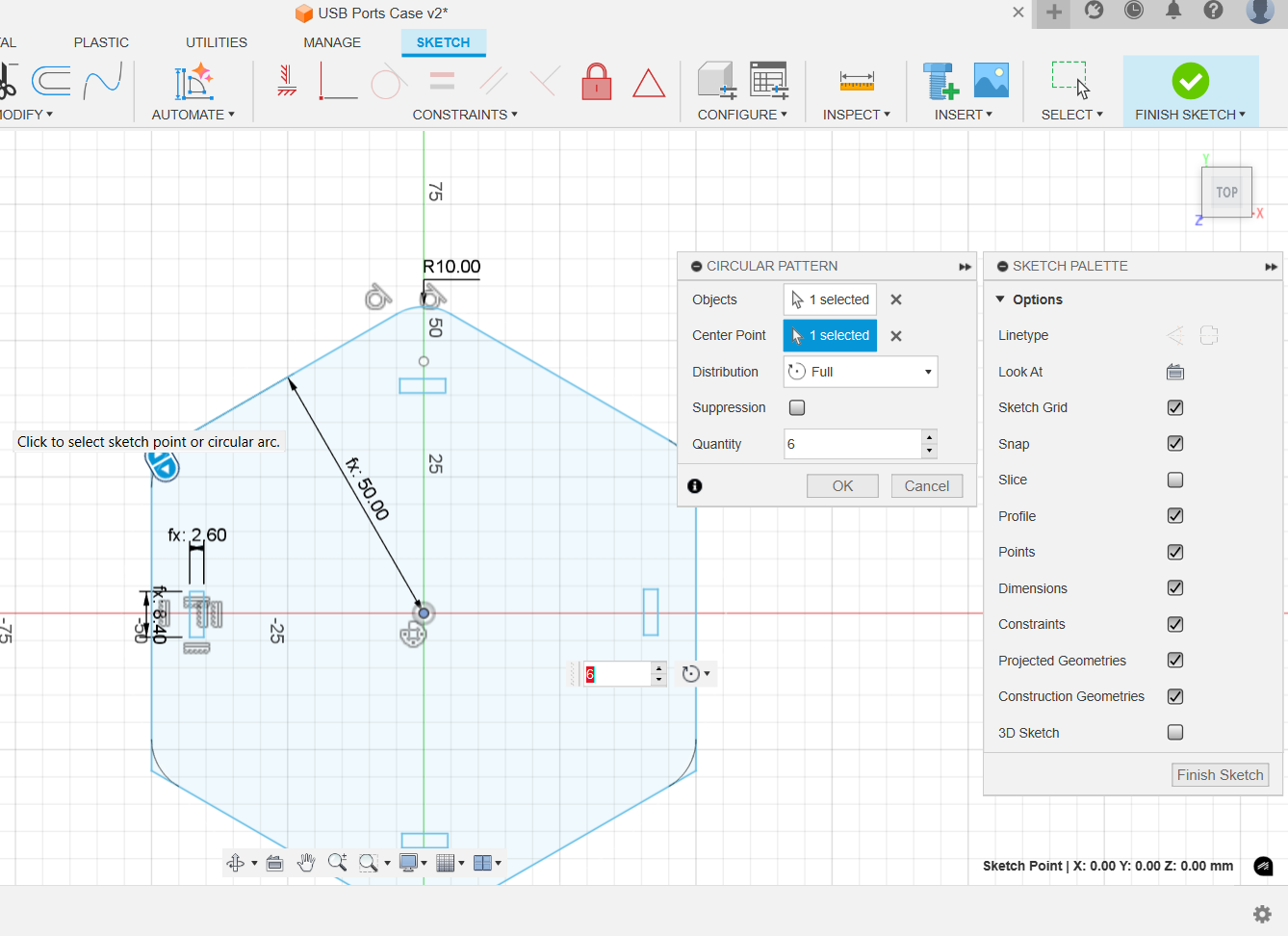
Using Fillets
To keep smooth rounded edges for the case as well as the ports, I used
fillet of 10 mm and 1 mm, respectively., the Vertical/Horizontal
To make the process more efficient, I applied the fillet on only one side of the case and
one port and then again used circular pattern to replicate on the rest.
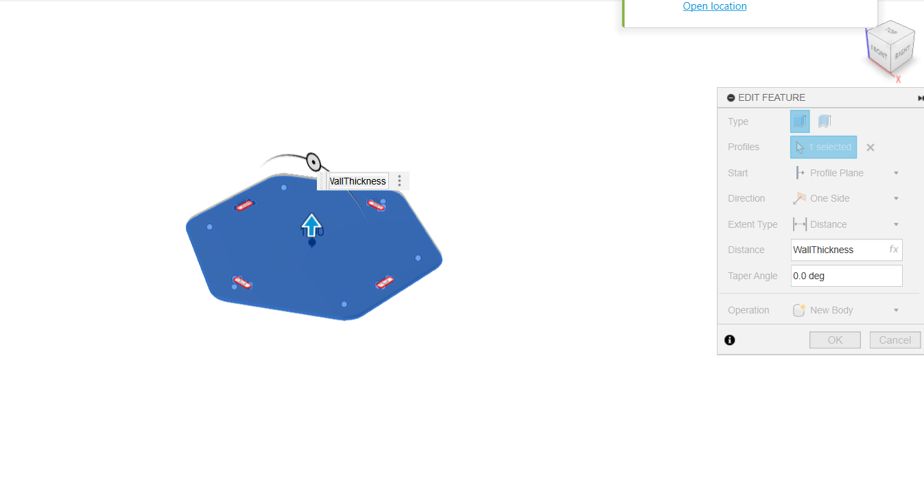
Extrude the USB-ports Case
The main body of the case is extruded while excluding the USB ports.
The case thickness is set according to the predefined parameter using the
Extrude tool from the Solid menu.
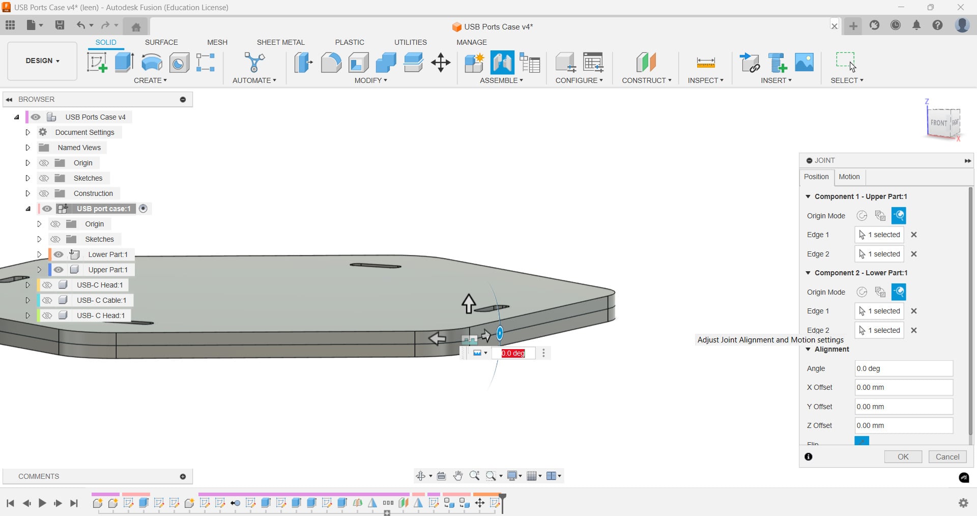
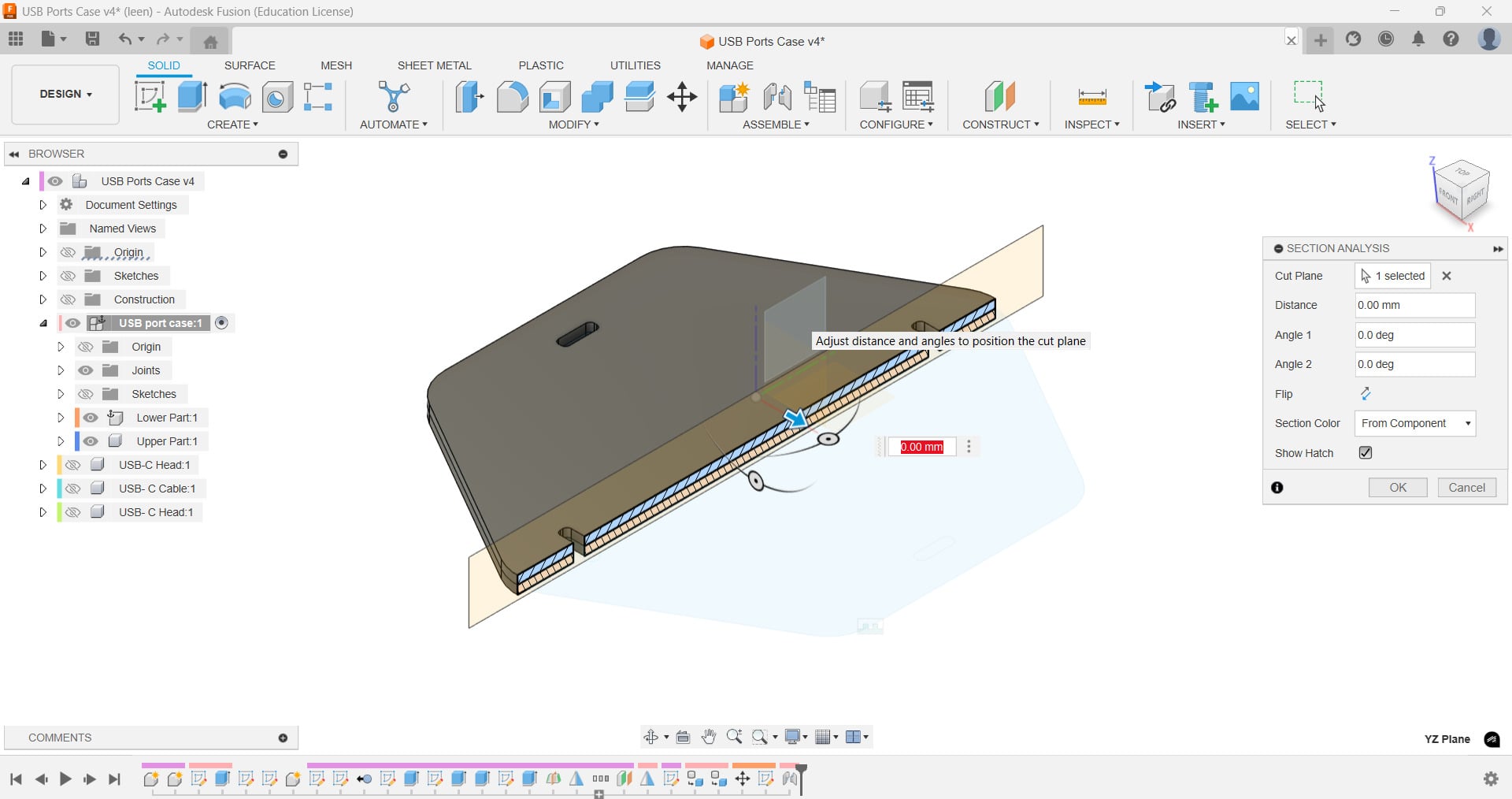
After mirroring the original lid to create a matching bottom half and
converting both halves
to individual components, I re-aligned them with a rigid joint to be sure the
case parts met
perfectly. I used section analysis to confirm alignment.
To experiment with more features, I decided to try and 3D model a USB-C cable!
Step 1: Design Type-C Connector
Sketch a rectangle using the USB-C set parameters for the connector end and extrude it 10 mm.Step 2: Add Port Details
Sketch the internal details of the USB-C port (12 pin layout) using the rectangle tool (width= 0.4 mm and length = 0.8 mm), rectangular pattern to ensure equal distance between the pins, and Extrude to create pins (0.2mm).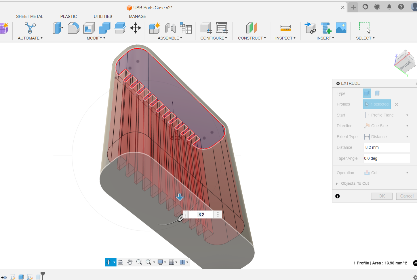
Step 3: Create the Cable Body
Sketch a circle of 2 mm on the bottom side of the connector for the cable cross-section and extrude it 100 mm.Step 4: Mirror the Connector
Create a midplane using Construct → Midplane between the cable ends. Then use the Mirror tool to duplicate the connector on the opposite end.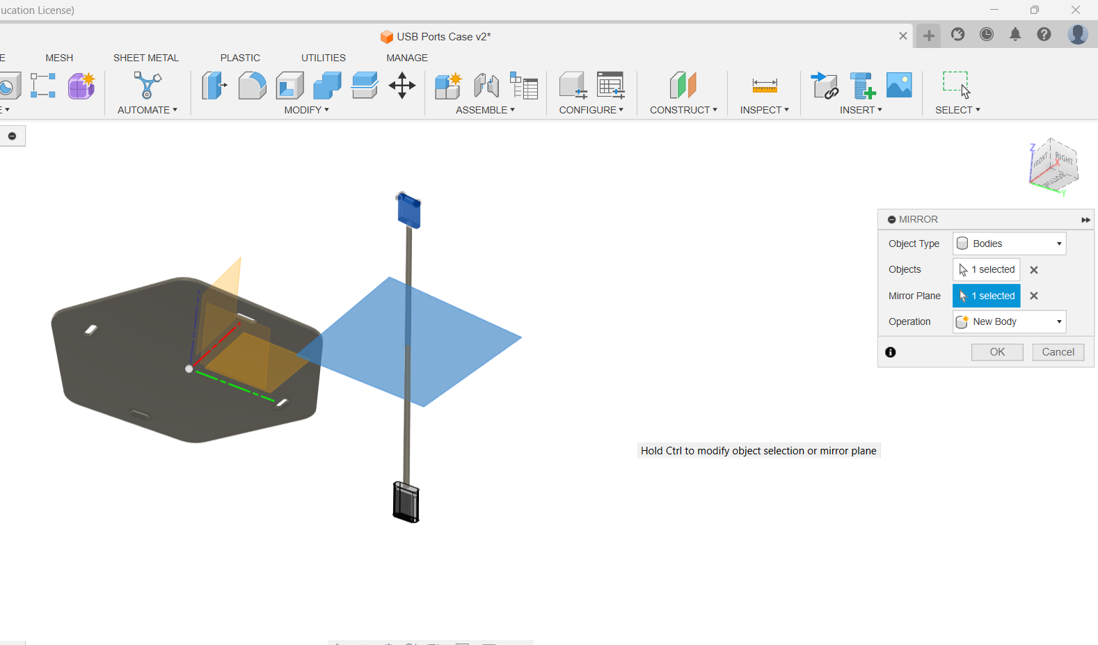
Step 5: Cable Enlargement and Fillet
To keep the cable looking realistic, the rod was press-pulled outwards by 1.5 mm to reach a 4 mm diameter, and a 1 mm fillet was applied where it meets each connector so it creates a smoother transition between the cable and the USB connector head.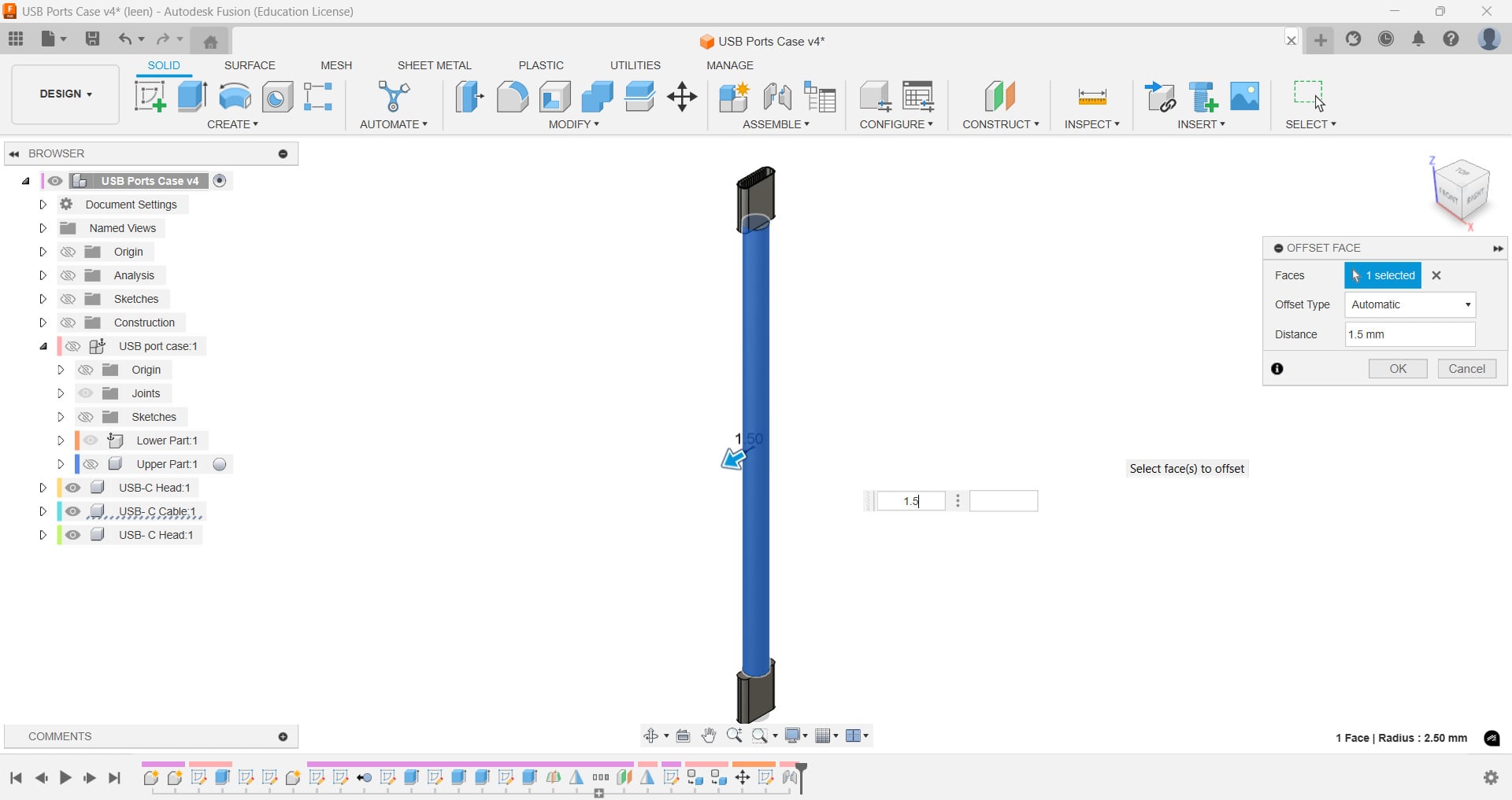
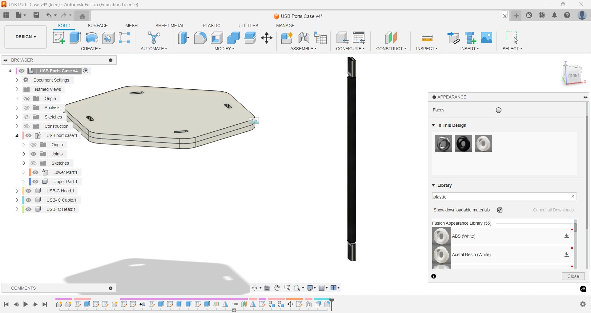
Appearance Feature
Finally I added appearances to distinguish materials:
a satin steel for the USB-C shells, black ABS for the inner contacts,
black hard rubber for the cable jacket, and white ABS for the case.
Final Homeview of the USB-ports Case and the cable
Finally, the USB-ports case with the cable are complete!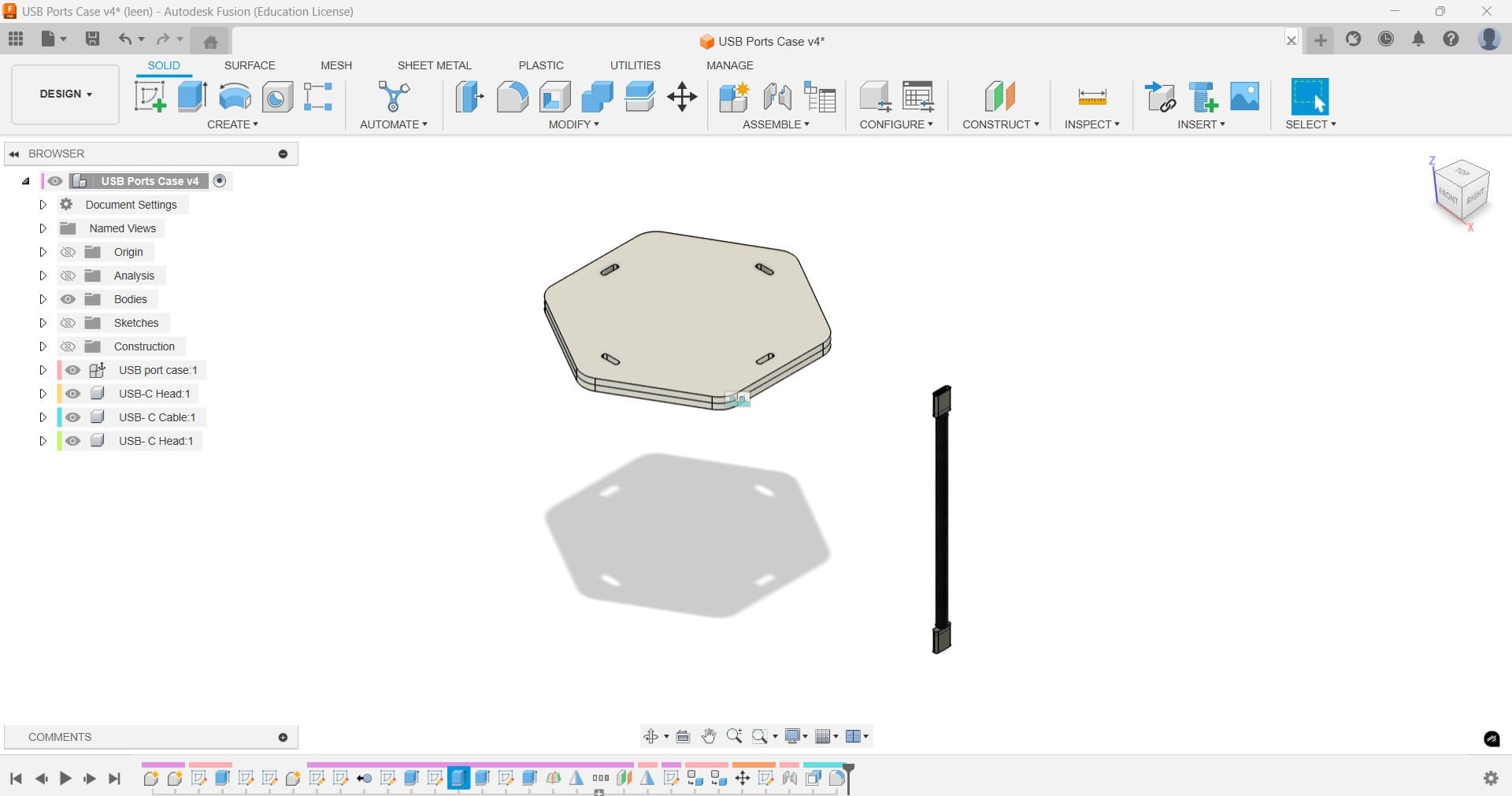
Reflection on Experience with GIMP, Inkscape, and Fusion360
I used a variety of design tools for this assignment, including GIMP, Inkscape, and Fusion 360,
each of which had special advantages that improved my work.
From my experience, I can say that GIMP is a powerful, simple, and open-source image editor,
which made it easier to create GIF animations and convert SVG frames to PNG format.
Whereas Inkscape is a key tool for creating accurate and scalable drawings. I used Inkscape's
vector features to create several frames of a sprouting sapling, making sure that each frame was
clear and consistent.
Both softwares made the design process simple and efficient because of their comprehensive
feature sets and user-friendly interfaces.
As for 3D modeling, Fusion360 offers a complete platform for designing intricate structures for
3D modeling projects.
I experimented with it to construct a case with USB ports, implementing parametric design
capabilities and accurate dimension control.
When trying to model a cable, I noticed it was way harder that I expected. I am aware that it is
not realistic and proper desing for the inner contacts specifically is still needed.
Nevertheless, I think
with applying tools like extrude, mirror and construct midplane, I was able to get to it as
close as possible with my small experience now.
Compressing Image Practice
Since we have a storage limit in our GitLab repository, getting used to
reducing and compressing images and videos is highly recommended.
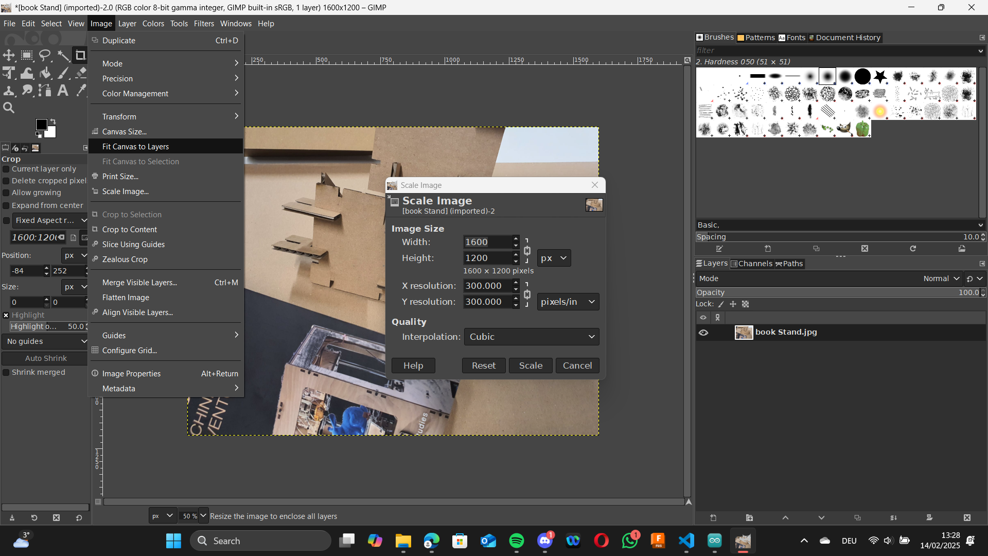
I tried experimenting with GIMP as
I have it already installed in my laptop. Other than creating .Gif animation like what we didWeek 2, GIMP offers tools to adjust image size, resolution, and format
to accomodate it to your needs.
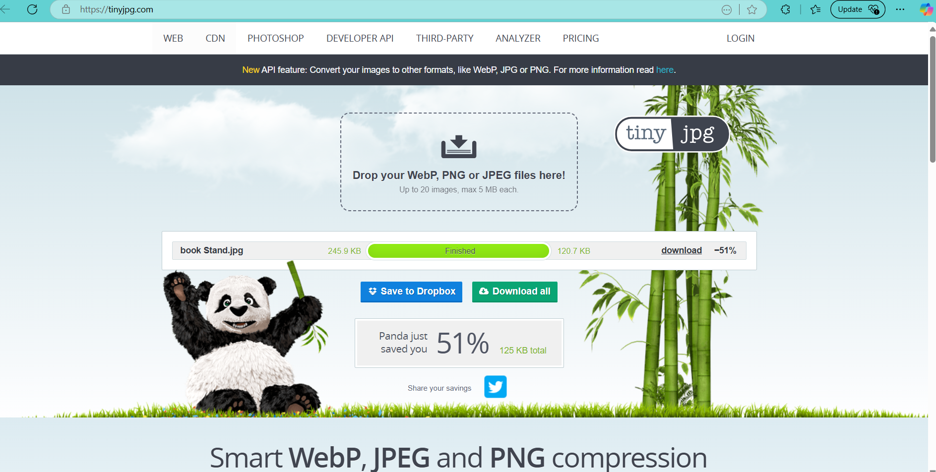
Moreover, there are some online tools that permit reducing the size of the image, while keeping
resolution the same, such as tiny jpg.
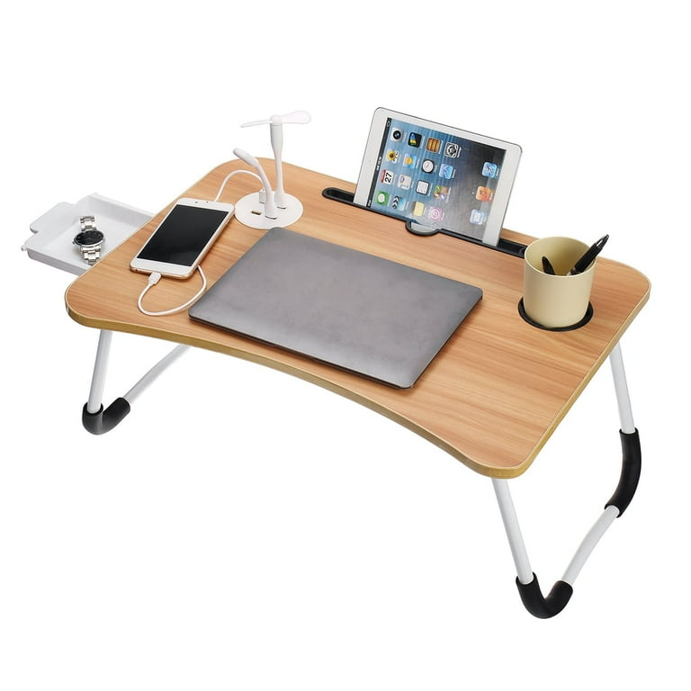
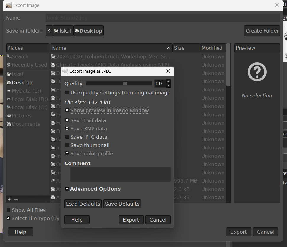
Example, my Book Stand image size before compression: 245.9KB.
1. After compression with GIMP: 142.4KB (with Quality = 60%).
 2. After compression with tinyjpg: 120.7KB.
Compressing Video Practice
I used freeconvert to compress my videos in Week 4-Embedded Programming.
freeconvert is
an online tool that allows for easy and efficient video compression without sacrificing
quality.