Embedded Programming
Group Assignment
- Demonstrate and compare the toolchains and development workflow for available embedded architectures.
Individual Assignment
- Browse through the data sheet for your microcontroller, write a program for a microcontroller, and simulate its operation, to interact (with local input &/or output devices), and communicate (with remote wired or wireless connections)
This week I started practicing some Arduino and programming using simulators.
Reading through ESP32 datasheet
For acquiring the datasheets, I found a good source called AllDataSheet. I downloaded the datasheets for ESP32 , and both DHT22 and LM35 temperature
sensors I will possibly use for my Final
Project
ESP32 Descrition
The ESP32 Development Board is a versatile microcontroller platform, suitable for IoT applications, Remote
Control and Monitoring, and embedded systems. It can communicate wirelessly with sensors, actuators, and
other devices since it integrates Bluetooth and Wi-Fi capabilities.
The ESP32 series of chips includes many modules such as ESP32-WROOM, ESP32-WROVER and ESP32-C. The CPU has
Xtensa single-/dual-core 32-bit LX6 microprocessor(s)
For specific task, I selected ESP32-S3. Due to its various features, it is high on my list to use for final project
microcontroller!
- CPU: Dual-core low-power Xtensa® LX7 microprocessors.
- Clock Speed: Up to 240 MHz.
- Flash Memory: Configurable; typically 4 MB.
- RAM: 512 KB SRAM.
- Wireless Connectivity:
- Wi-Fi: 2.4 GHz (IEEE 802.11 b/g/n).
- Bluetooth: Bluetooth 5 (LE).
- FTDI Connection: Used for programming and serial communication.
- I2C Connection: Supports multiple devices via the I2C bus (SDA/SCL).
- UART Connection: Two UART interfaces for serial communication.
- SPI Connection: High-speed SPI interface for peripherals.
- GPIO (General Purpose Input/Output): 45 programmable pins (configurable as input, output, or special functions).
- Analog Inputs: 18 channels of 12-bit ADC (Analog-to-Digital Converter).
- Digital Outputs: 2 channels of 8-bit DAC (Digital-to-Analog Converter).
- PWM: Multiple channels for fan control or light dimming.
- Onboard LED: Built-in LED connected to GPIO 2.
- Onboard Button: Boot and Reset buttons for programming and restarting the device.
- Power Supply: Micro-USB input for power and programming, and 3.3V regulated output from 5V USB for powering external sensors or modules.
Coding Pins
The following table describes the relationship between the board pinout and the corresponding GPIO numbers for coding:
Board pinout |
GPIO |
Function |
Description |
|---|---|---|---|
| GND | 1, 15, 38 | Pin | Reference point for all voltages |
| 3V3 | Pin | Voltage Common Collector or VCC | Power supply/ input |
| LED_Builtin | 2 | Digital Output | Onboard LED control |
| Button | 0 | Digital Input | Boot Mode selection/ input |
| SDA | 21 | I2C Data | I2C communication |
| SCL | 22 | I2C Clock | I2C Communication |
| RX0 | 3 | UART RX | Serial communication |
| TX0 | 1 | UART TX | Serial communication |
| DAC1 | 25 | Digital-to-Analog Output | Analog output for audio or DAC use |
| DAC2 | 26 | Digital-to-Analog Output | Analog output for audio or DAC use |
| ADC1_CH0 | 36 | Digital-to-Analog Output | Analog sensor input |
| ADC1_CH3 | 39 | Digital-to-Analog Output | Analog sensor input |
ESP32 Pinout Schematic
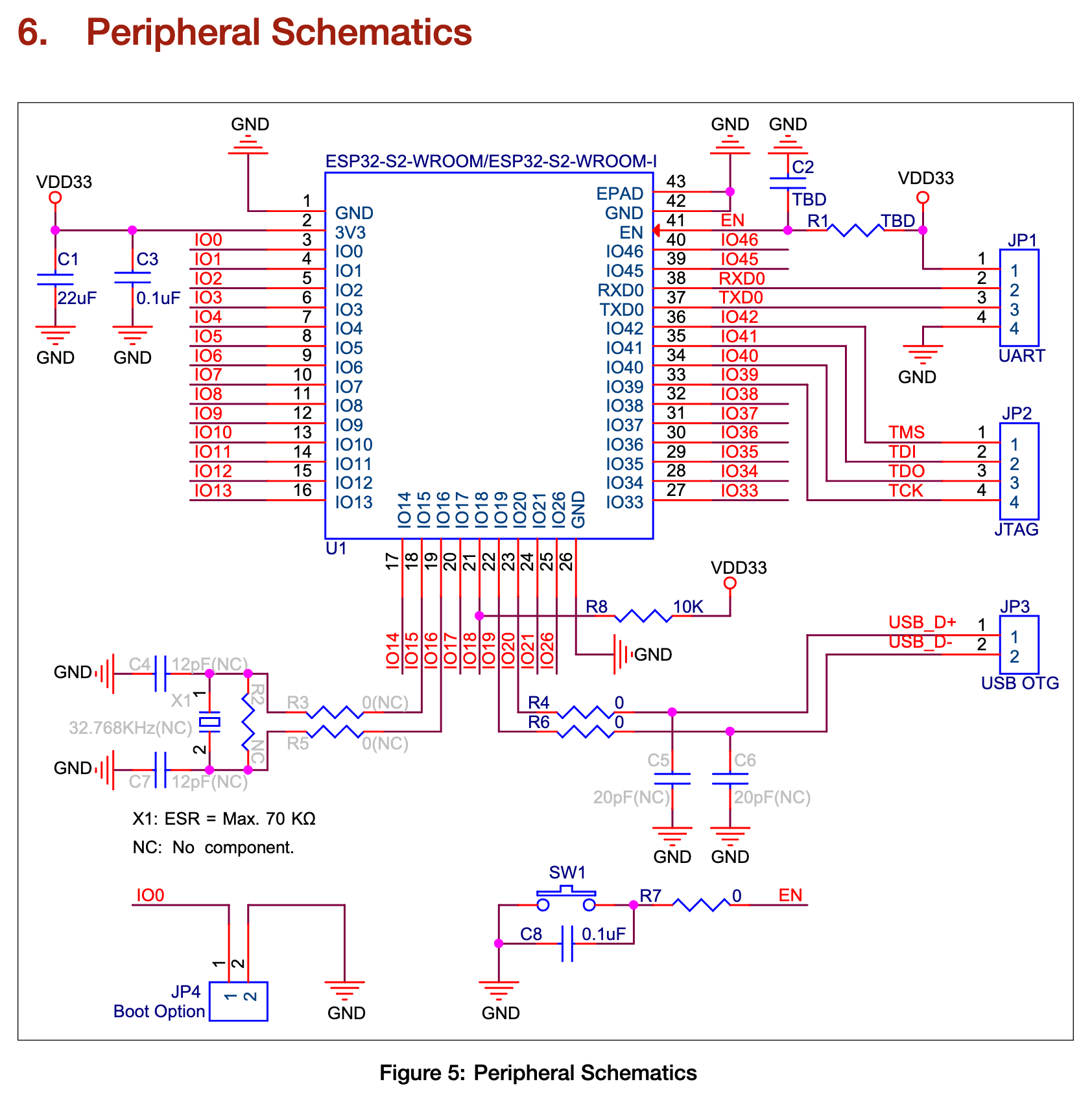
Eggsampler. PeripheralSchematics.png. GitHub, n.d.,
Simulating ESP32 microcontroller with LED Output
I decided to use the extension for Wokwi on Visual Studio Code, since the online server was taking very long time due to heavy
load around the globe from us FabAcademy student :D
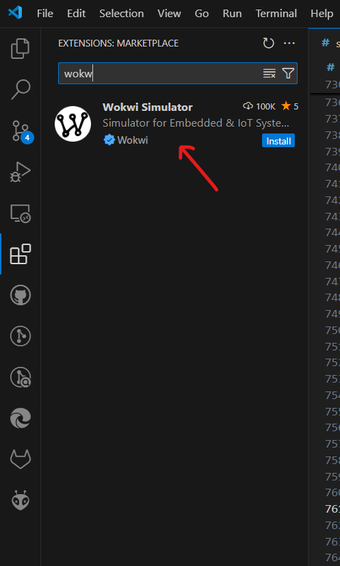 . Additionally,
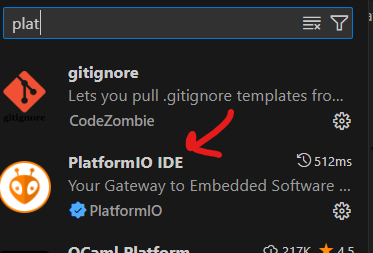
I installed PLatformio to create a and IDE compatible in VS Code.
. Additionally,
I installed PLatformio to create a and IDE compatible in VS Code.
After downloading both extensions, press Ctrl+Shift+P to open the
Command Palette. Then, type "Wokwi: Request a new License" and select it. A prompt will ask you to confirm
opening the Wokwi website in your browser. Click "Open"
A project template with the necessary files will be created.
After trying to change the source in the GitLab repository and watching youtube tutorial on how to change
the .src file and the .json file, I got error that some libraries are not compatible.
To avoid damaging my website and after lengthy plenty attempts and getting confused while working on
Platformio, I decided to go back to the online version of Wokwi and keep on trying. I will practice more to get the hang of it!
Arduino IDE for developing my microcontroller
First, I downloaded Arduino IDE.
Arduino IDE is an Integrated Development Environment used for writing and uploading code to Arduino boards.
It features a text editor for composing code, an error message area, a text console, a toolbar with common
functions such as verify code, compile and select board type.
Additionally, you can use the library manager to download the libraries supporting your component
(microcontroller, input, or output devices).
To install Arduino support package for ESP32 following these steps.
Since for this task I have to only do simulation, I just wanted to set up my working environment for future
assignments.
Code Implemented with ESP32
LED and pressing Button
This Arduino code reads a button's state and controls an LED accordingly, while printing the button's status
to the serial monitor.
The setup() function's code defines the LED pin as an output and the button pin as an input, with an
internal pull-up resistor to maintain a stable HIGH state when the button is not pressed. It also
initializes serial communication at baud rate of 9600.
The loop() function continuously checks the button's state. Pressing the button causes the LED to glow (LOW
because of the pull-up resistor) and prints the message "Button pressed" onto the Serial Monitor. The LED
turns off when it is released, and a new message that reads "Button released" appears.
The buttonState variable is used to track this state change.
Press Button turn on LED Practice
Pressingbuttonled.inoBlinking LED with Button Practice
BlinkingLED.inoNTC Temperature Sensor Practice
TemperatureSensor.inoLCD Display of Temperature
LCD-Temp.ino
// the setup function runs once when you press reset or power the board

#include

const int buttonPin = 26;
const int ledPin = 27;

bool buttonState = false;

void setup() {
  // the setup function runs once when you press reset or power the board

Serial.begin(9600); // Initialize serial communication
pinMode(ledPin, OUTPUT); // Set LED pin as output
pinMode(buttonPin, INPUT_PULLUP); // Set button pin as input with internal pull-up resistor

}

void loop() {
// the loop function runs over and over again forever

  bool currentButtonState = digitalRead(buttonPin) == LOW; // Button pressed when LOW

  if (currentButtonState != buttonState) {  // Button has either been pressed or released since the last check
    if (currentButtonState) {  // If currentButtonState is true (button pressed):
      digitalWrite(ledPin, HIGH); // The LED is turned ON by setting it HIGH
      Serial.println("Button pressed");  // A message "Button pressed" is sent to the serial monitor
    } else {   // If currentButtonState is false (button released):
      digitalWrite(ledPin, LOW); // The LED is turned OFF by setting it LOW
      Serial.println("Button released"); // A message "Button released" is sent to the serial monitor
    }
    buttonState = currentButtonState; // Update button state
  }

  delay(50); // Short delay for button debounce
}
Blinking LED with a Button
This Arduino code toggles an LED to blink twice when a button is pressed, using debounce logic to prevent
false triggers.
In the setup () function, the code initializes serial connection at a baud rate of 9600, the LED and
button pins, and the button is configured to use an internal pull-up resistor.
The button status is continuously monitored in the loop() function. In order to prevent numerous
detections of the same button push, the program uses a 50 ms debounce delay to verify that the button
press is true.
The blinking is toggled if the press is valid. The LED turns on and off twice when in blinking mode, with
a 500 ms delay between each switch. The LED stops glowing after it has finished, and you can toggle the
blinking status by pressing the button again.
    const int buttonPin = 26;
    const int ledPin = 27;

    bool ledBlinking = false;   // Flag to track LED blinking state
    unsigned long lastPressTime = 0;  // Timestamp of the last button press
    unsigned long debounceDelay = 50; // Debounce delay in milliseconds

    void setup() {
      // the setup function runs once when you press reset or power the board

      pinMode(ledPin, OUTPUT);  // Set LED pin as output
      pinMode(buttonPin, INPUT_PULLUP); // Set button pin as input with internal pull-up resistor
    }

    void loop() {
      // the loop function runs over and over again forever

      static bool lastButtonState = HIGH; // Previous button state
      bool currentButtonState = digitalRead(buttonPin); // Current button state

      // Check for button press with debounce, was previously not pressed, and is now pressed
      if (lastButtonState == HIGH && currentButtonState == LOW && (millis() - lastPressTime) > debounceDelay) { // Ensure debounceDelay time has passed since the last press
        lastPressTime = millis(); // Update lastPressTime to the current time (from millis())
        ledBlinking = !ledBlinking; // Toggle LED blinking state
      }
      lastButtonState = currentButtonState; //Update lastButtonState to the current state for the next loop iteration

      if (ledBlinking) { //If the LED is in blinking mode
        // Blink LED twice with a 0.5s delay
        for (int i = 0; i < 2; i++) { // A loop to blink the LED twice.
          digitalWrite(ledPin, HIGH); //Turn ON LED for 0.5 s
          delay(500);
          digitalWrite(ledPin, LOW); //Turn Off LED for 0.5 s
          delay(500);
        }
        ledBlinking = false; // Reset after blinking
      } else { //  If ledBlinking is false, the LED remains off
        digitalWrite(ledPin, LOW); // LED is off when not blinking
      }
    }
ESP32 with Temperature Sensor NTC
Since I want to use a temperature sensor in my final project, I thought practicing a simple example for it
would be a good idea!
The following Arduino code reads temperature from NTC thermistor and show them on the Serial Monitor.
Additionally, it uses a button press to control an LED as in the previously shown examples.
To avoid repetition, I will only explain the parts related to the NTC thermistor.
In the loop() function, the code implements the analogRead() function to read the analog value from the
NTC thermistor attached to pin A0 (GPIO36). The ESP32's 12-bit ADC means that the read value can be
anything between 0 and 4095.
This value is multiplied by the reference voltage (3.3V) and divided by the ADC resolution (4095) to
determine a voltage.
The code then uses the voltage divider formula to calculate the NTC resistance (See
Voltage Divider (article) | Circuit analysis - Khan Academy). A fixed 10kΩ resistor is connected in
series with the thermistor. The resistance of the NTC is computed using the measured voltage.
Next, the temperature is determined using the Beta parameter equation (See NTC Thermistors - Calculate Beta Values -
Ametherm), which yields a precise temperature conversion from NTC resistance. This method takes into
consideration the NTC's non-linear resistance change with temperature.
It makes use of constants like the resistance of the NTC at 25°C (10kΩ), the reference temperature in
Kelvin (25°C = 298.15K), and the Beta value (3950), which is specific to the thermistor model.
Lastly, the loop repeats every one second, and the computed temperature (in °C) is displayed on the Serial
Monitor.
    #include

      const int buttonPin = 26;
      const int ledPin = 27;
      const int tempSensorPin = 35;

      // Parameters for the Voltage Divider
      const float Vref = 3.3;  // ESP32 ADC reference voltage
      const int ADC_Max = 4095;  // 12-bit ADC resolution
      const int R_fixed = 10000; // Fixed resistor value (10kΩ)

      bool buttonState = false; // Variable to hold the button state

      void setup() {
        // Initialize serial communication
        Serial.begin(9600);
        pinMode(ledPin, OUTPUT); // Set LED pin as output
        pinMode(buttonPin, INPUT_PULLUP); // Set button pin as input with internal pull-up resistor
      }

      void loop() {
        bool currentButtonState = digitalRead(buttonPin) == HIGH; // Button pressed when HIGH

        if (currentButtonState != buttonState) {
          if (currentButtonState) {
            digitalWrite(ledPin, HIGH); // Turn LED on
            Serial.println("Button pressed");
          } else {
            digitalWrite(ledPin, LOW);  // Turn LED off
            Serial.println("Button released");
          }
          buttonState = currentButtonState; // Update button state
        }

   // Read temperature sensor value (analog voltage) from the temperature sensor and store it in tempValue
  int tempValue = analogRead(tempSensorPin);

  // Avoid division by zero by checking if Vout is close to Vref
  if (tempValue == 0 || tempValue == ADC_Max) { // If tempValue is 0 or equals ADC_Max (typically 1023 for a 10-bit ADC)
    Serial.println("Invalid sensor reading."); //  If an invalid reading is detected, it prints "Invalid sensor reading"
  } else {
    // Convert analog value to voltage
    float Vout = tempValue * (Vref / ADC_Max); //Vout is computed by scaling tempValue to the reference voltage (Vref)

    // Calculate the NTC resistance using the Voltage Divider formula
    float R_NTC = (R_fixed * (Vref - Vout)) / Vout;

    // Calculate Temperature using the Beta parameter equation
    float Beta = 3950.0; // Beta parameter for the NTC thermistor
    float T0 = 298.15; // Reference temperature (25°C in Kelvin)
    float R0 = 10000.0; // NTC resistance at 25°C (10kΩ)
    float temperatureK = (Beta * T0) / (Beta + (T0 * log(R_NTC / R0))); // Beta Parameter eauatioq
    float temperatureC = temperatureK - 273.15; Converting to Celsius

    // Print the temperature in Celsius to Serial Monitor
    Serial.print("Temperature: ");
    Serial.print(temperatureC);
    Serial.println(" °C");
  }

  delay(1000); // Delay 1 s before next reading
}
Displaying Temperature on I2C LCD
The code configures an analog temperature sensor on pin 33, a button on pin 12, and an LED on pin 14 in
addition to initializing the required libraries for the I2C LCD display.
The defined constants include the reference voltage (3.3V), the maximum ADC value (4095 for ESP32), the
fixed resistor value (10kΩ), the thermistor's beta value (3950) (see previous code), the reference
temperature (25°C), and other parameters for determining the temperature from the thermistor.
The analogRead() function is used in the loop() function to read the temperature sensor value,
implementing both the Voltage Divider formula the Beta parameter equation (see previous code).
On an LCD, the temperature is shown as "Cold," "Normal," or "Hot" according to preset temperature ranges.
For continuous monitoring, the loop is programmed to repeat once every second.
    #include
      #include
      #include

      // LCD I2C address and dimensions
      LiquidCrystal_I2C lcd(0x27, 16, 2);

      // Pin definitions
      const int tempSensorPin = 33;
      const int buttonPin = 12;
      const int ledPin = 14;

      // Constants for temperature calculation
      const float Vref = 3.3;       // Reference voltage
      const int ADC_Max = 4095;     // Maximum ADC value for ESP32 (12-bit ADC)
      const float R_fixed = 10000;  // Fixed resistor value in ohms
      const float Beta = 3950.0;    // Beta parameter for the NTC thermistor
      const float T0_ref = 298.15; // Reference temperature (25°C in Kelvin)
      const float R0 = 10000.0;     // NTC resistance at 25°C (10kΩ)

      void setup() {
        // Initialize serial communication
        Serial.begin(115200);

        // Initialize the LCD
        lcd.init();
        lcd.backlight();

        // Initialize the button pin
        pinMode(buttonPin, INPUT_PULLUP);

        // Initialize the LED pin
        pinMode(ledPin, OUTPUT);
      }

      void loop() {
        // Read temperature sensor value
        int tempValue = analogRead(tempSensorPin);

        // Avoid division by zero by checking if Vout is close to Vref
        if (tempValue == 0 || tempValue == ADC_Max) {
          Serial.println("Invalid sensor reading.");
        } else {
          // Convert analog value to voltage
          float Vout = tempValue * (Vref / ADC_Max);

          // Calculate the NTC resistance using the Voltage Divider formula
          float R_NTC = (R_fixed * (Vref - Vout)) / Vout;

          // Calculate Temperature using the Beta parameter equation
          float temperatureK = (Beta * T0_ref) / (Beta + (T0_ref * log(R_NTC / R0)));
          float temperatureC = temperatureK - 273.15; // Convert to Celsius

          // Print the temperature to Serial Monitor
          Serial.print("Temperature: ");
          Serial.print(temperatureC);
          Serial.println(" °C");

          // Display appropriate message based on temperature on LCD
          lcd.clear();
          if (temperatureC < 15) {
            lcd.print("Cold");
          } else if (temperatureC >= 15 && temperatureC <= 25) {
            lcd.print("Normal");
          } else {
            lcd.print("Hot");
          }

          // Display the temperature on the second line of the LCD
          lcd.setCursor(0, 1);
          lcd.print(temperatureC);
          lcd.print(" C");
        }

        delay(1000); // Delay 1 second before next reading
      }
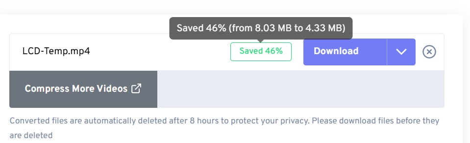
I used this online tool to compress my videos freeconvert.
compression video example: the last video record showing the temperature print on the LCD
was 8.04 MB. Once I uploaded the video on the freeconvert and pressed compress video and waited couple of
seconds. After compressrion, freeconvert informed that 46% space was saved, decreasing the size of the video down
to 4.33 MB.
YouTube Tutorials:
- ESP32 for Beginners This playlist offers a comprehensive introduction to ESP32.
- ESP32: Blink the LED (ESP32 + Arduino series)
- Install and get started with Wokwi in VS Code
Files
Pressingbuttonled.ino
BlinkingLED.ino
TemperatureSensor.ino
LCD-Temp.ino