System Integration
- Design and document the system integration for your final project
System Integration Overview
For sketching this overview, I used Paint.
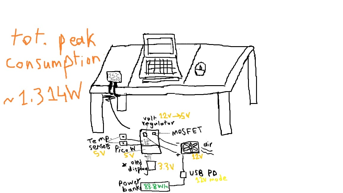
Electronics Components Datasheets
- Raspberry Pi Pico W
- NDS355A Mosfet
- Linear Voltage Regulator D²PAK
- two DS18B20 temperature sensors
- SBC-OLED01.3
- Fan 12 V
- USB PD (Power Delivery) trigger module
Overall Power Consumption for the Electronics
Values taken from component datasheets where available. In order to be
able to calculate consistently the power consumption, considering that different components
require different voltage input values, power was calculated using the peak current values:
P = V×I (W)| Component | Supply Voltage (V) | Peak I (A) | Peak P (W) |
|---|---|---|---|
| Raspberry Pi Pico W | 5.0 | 0.0955 (without saving mode) | 0.478 |
| NDS355AN MOSFET (gate drive) | 3.3 | 0.0017 (pulsed) | 0.0056 |
| Linear Regulator L78-05 (D²PAK) | 5.0 | 0.0800 | 0.400 |
| DS18B20 Sensors (×2) | 5 | 0.0015 (drain/sink) | 0.00495 |
| SBC-OLED01.3 Display | 3.3 | 0.0207 (100% contrast and brightness, check link) | 0.0683 |
| DC Fan | 12 | 0.0290 | 0.36 |
| Total Peak Current | 0.0955 A + 0.0017 A + 0.0800 A + 0.0015 A + 0.0207 A + 0.0290 A = ≈ 0.2284 A | ||
| Total Peak Power | (5.0 V × 0.0955 A) + (3.3 V × 0.0017 A) + (5.0 V × 0.0800 A) + (5 V × 0.0015 A) × 2 + (3.3 V × 0.0207 A) + (12.0 V × 0.0290 A) = 0.478 W + 0.0056 W + 0.400 W + 0.204 W + 0.0683 W + 0.348 W ≈ 1.314 W | ||
Theoretically speaking, for a powerbank that has storage of 24 000 m A h
and 88.8 W h:
Run Time = 88.8 W h ÷ 1.324 w ≈ 67.069 hPractical Total Power Consumption Value
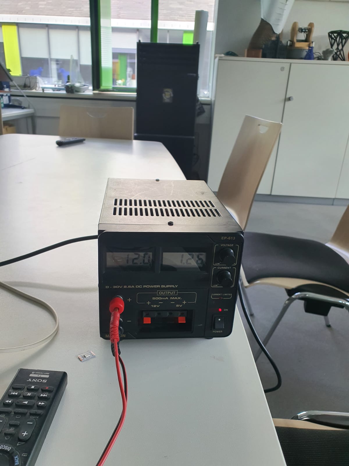
First test, I tried with a different fan that consumes way more current than the one I am
planning to use, because my actual fan still hasn't arrive. However, this deviation can be
considered as a safety limit value.
I used the powerbench to set the voltage to 12 v, then checked the power consumption → ≈
88 h
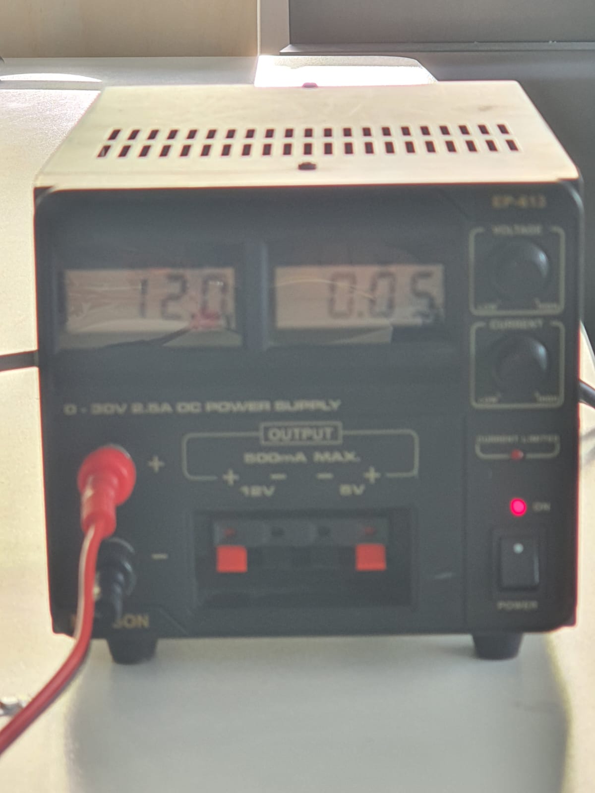
Afterwards, I unplugged the fan and checked the difference of the consumption; it went down
to ≈ 0.05 W. Simple math: considering the actual power consumption of the fan I want to use
(29 mA, 0.348 W),
My prediction would be; total power consumtion is ≈ 1.2 W. 0.9 - 1 W. This
means, my circuit will run for 88 h without needing to recharge the powerbank!
Nevertheless, I will repeat the test once the fan arrives to confirm my assumption
Designing Housing for the Electronics
First, I decided to use the caliper to take the measurements for each component to be able
to design around them.
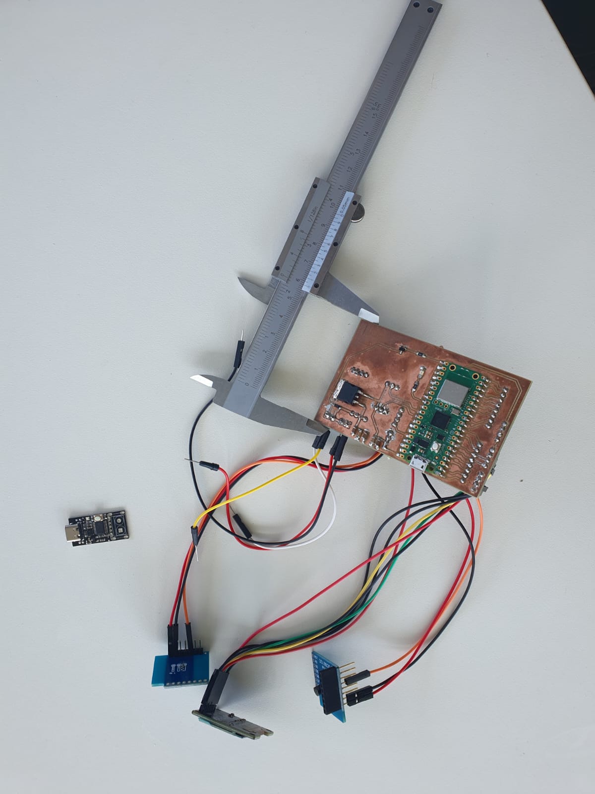
In the following table, you can find all three dimensions for each component (width,
length, thickness):
| Component | Length | Width | Thickness |
|---|---|---|---|
| PCB | 91 mm | 62 mm | 5 mm |
| DS18B20 Temperature Sensors | 28 mm | 26 mm | 9 mm |
| SBC - OLED01.3 Display | 36 mm | 34 mm | 4 mm |
| USB- C PD Module | 30 mm | 15 mm | 4 mm |
| Power Bank | 160 mm | 79 mm | 30 mm |
Then, as a second step, I went to Thingiverse to
explore whether I have any housing for my components that I can build and modify upon. I
found one for the OLED display.
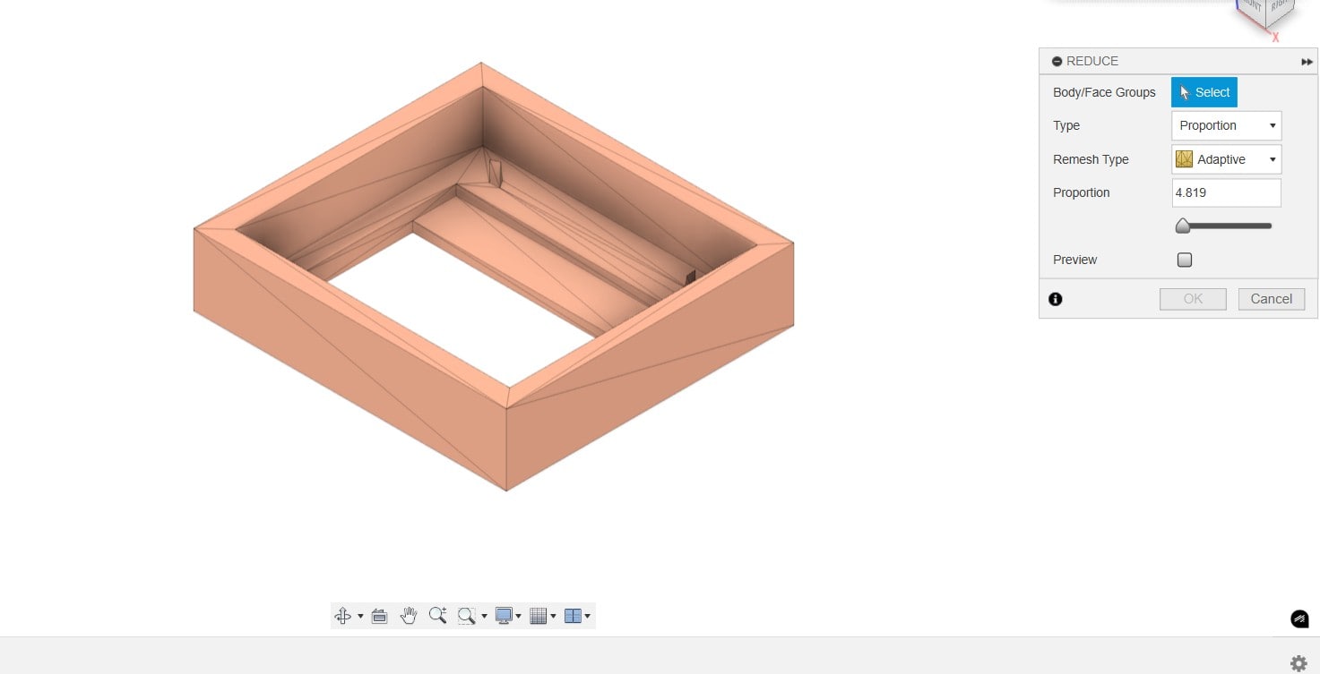
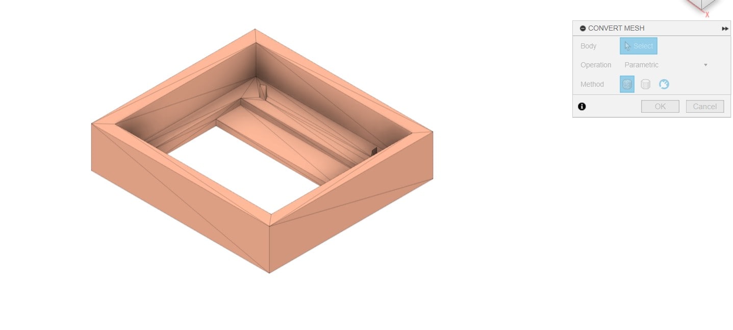
Hence, I downloaded the stl file and used the convert mesh tool to convert
the mesh body into a
solid body, after reducing the triangles density using
reduce in modify menu in order to be able to
modify on it easier.
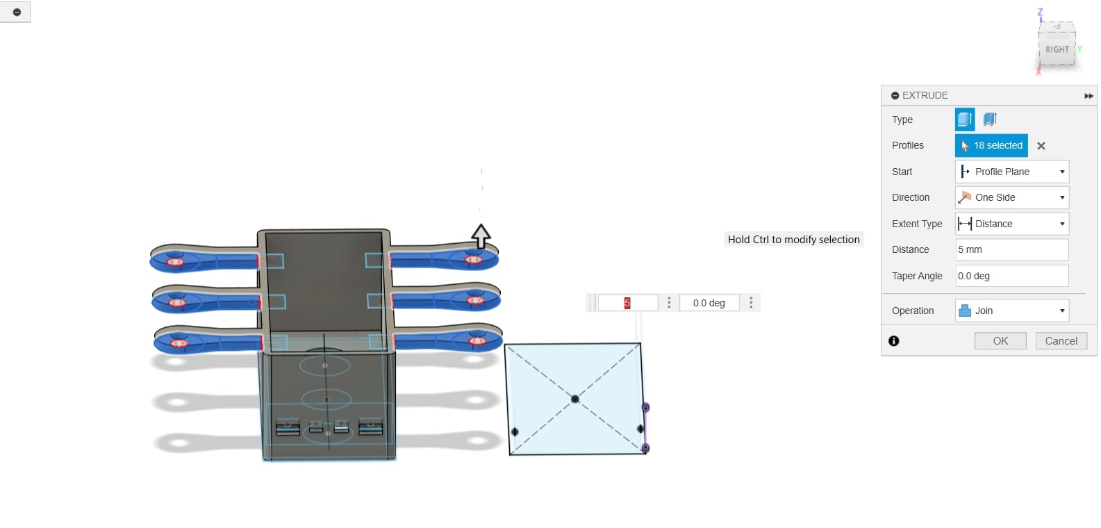
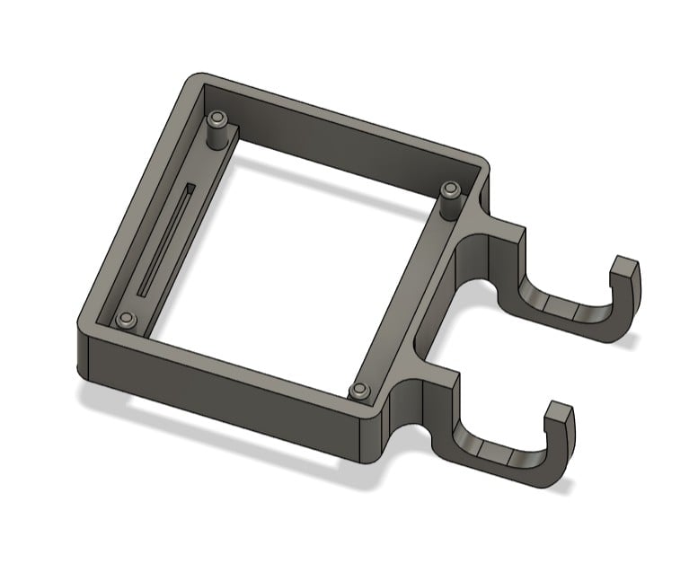
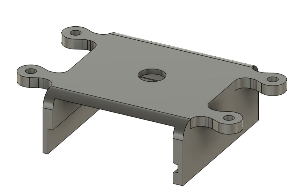
Designing OLED Display Housing
Next, using the measured dimensions of my oled display, I scaled it down to the right
dimensions to the display opening. As to fixate it, I extruded 4 pins to
fit into the holes of the display.
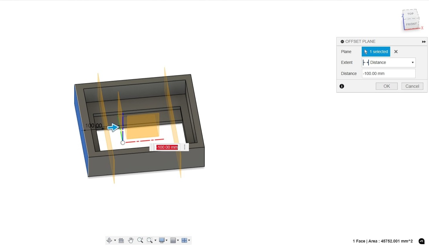
As for mounting it, I decided to use a clamp-like mechanism to have it
modular where I can move it from one side to the other. First, I used offsetplane
tool to have the sketch surface for two clamps at the bottom side of the display
housing.
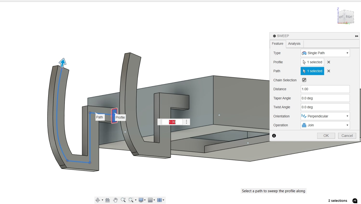
Then, using a combination of
line and spline tools, I managed to achied the right
sketch, bearing in mind the thickness of my plywood (12 mm + 15 mm).
Afterwards, I usedsweep to convert the sketch lines to the clamps solid
body (~2.5 mm thick) and joined them to the display
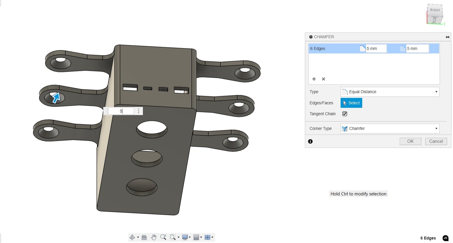
housing. To relieve the stress created between the PLA and the wood pulling in opposite
directions, I added few fillets on each stress point on the clamps (3 mm
and 5 mm fillets).
Lastly, for aesthetic purposes, I added a 2 mm fillet on the edges of the
housing.
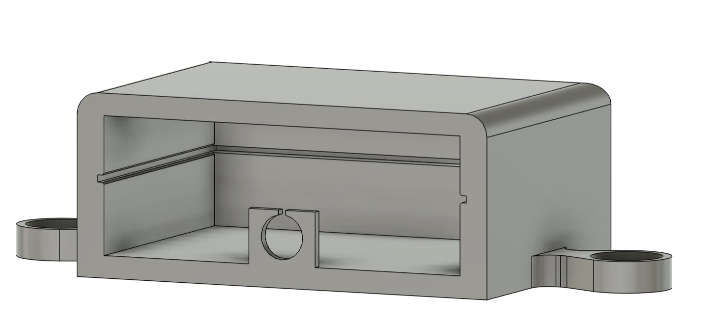
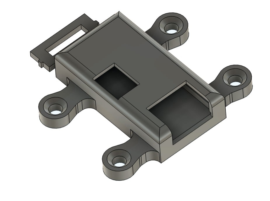
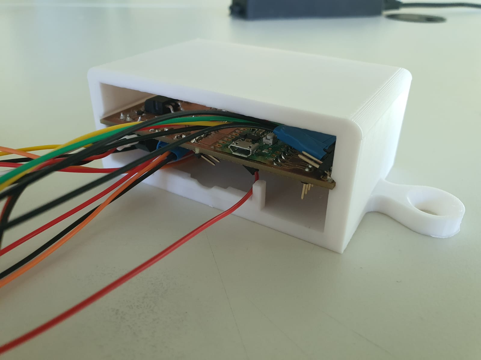
Designing the PCB Sliding Box
Using the the measured dimensions of my PCB, I drew a center rectangle and
extruded it to 41 mm in order to fit the PCB as well as the pinheaders
protruding from it.
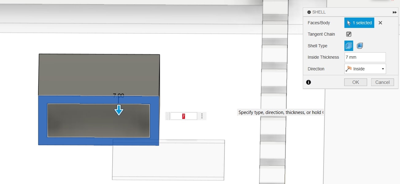
Next, using the shell feature, I turned it to an exposed box. In order to
slide the PCB insto the box, I sketched the channel on each inner face of
the box and cut ~1.5 mm deep to manage to hold the PCB.
For easier insertion, I added 0.4 mm chamfer on each edge of the channel.
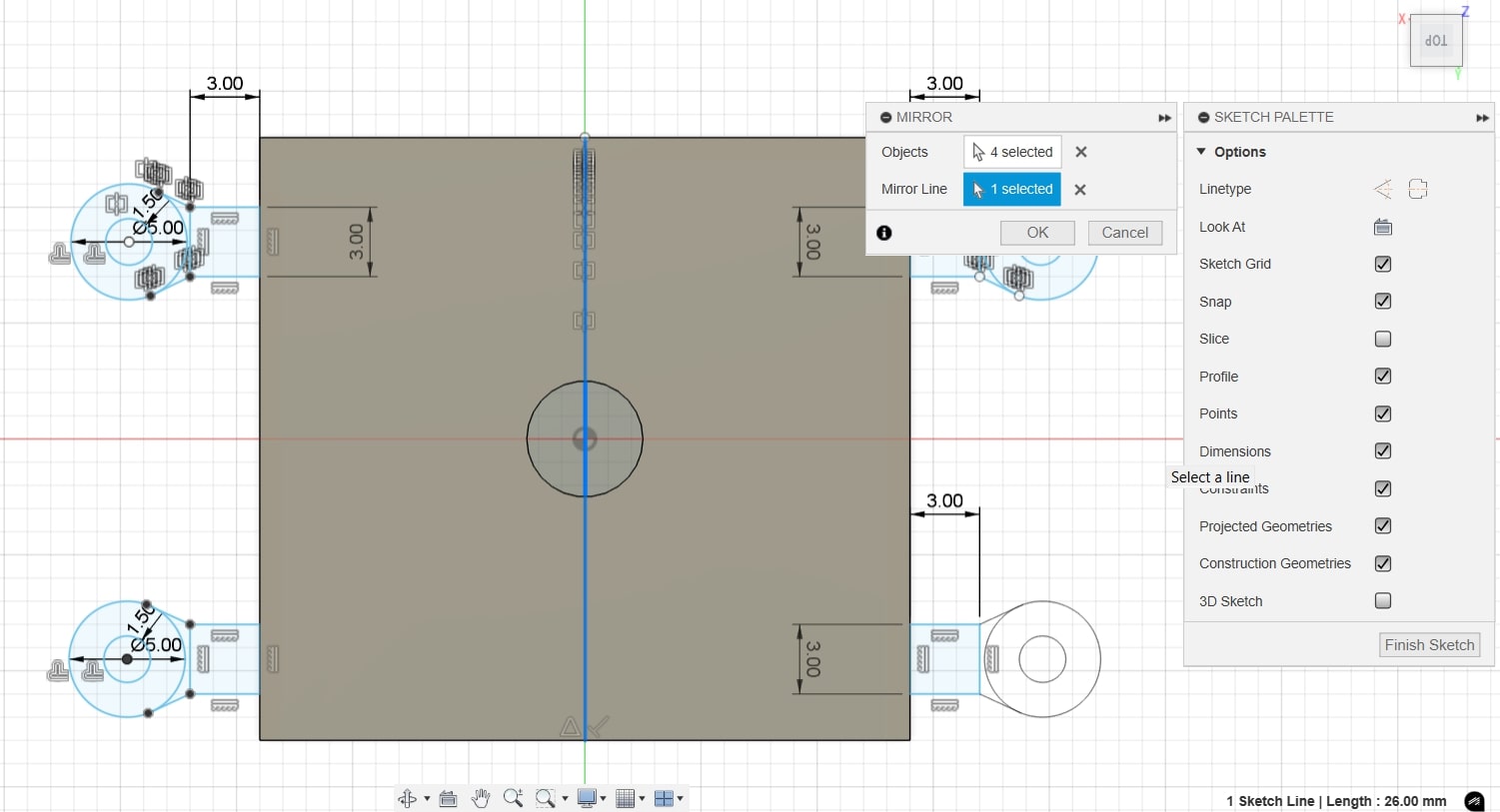
Moreover, to prevent the tangling of the cables coming out of it, I sketched and
extruded a circle, with an upper small cutout/ opening to
be able to insert the cables into it.
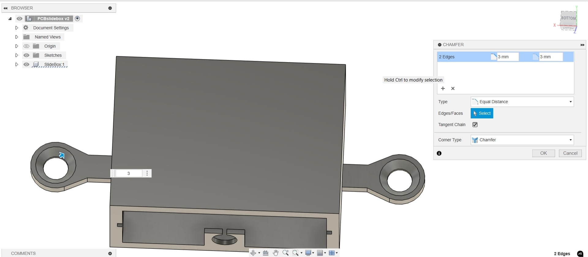
To be able to mount the box, I added two ear like extenstions on each side,
where a cut outcircle for screws and added 3 mm chamfers
to
compensate for the countersink of the screws. To size down the hole, I designed a washer
with the same thickness of the ear and projects the mating part of the chamfer-hole cut out
of the ears. Now a screw of 4 mm diameter should fit!
Moreover, for each stress point as previously explained, I added 4 mm
fillets between those ears and the box itself. This also helps reduce the
amount of support needed when printed!
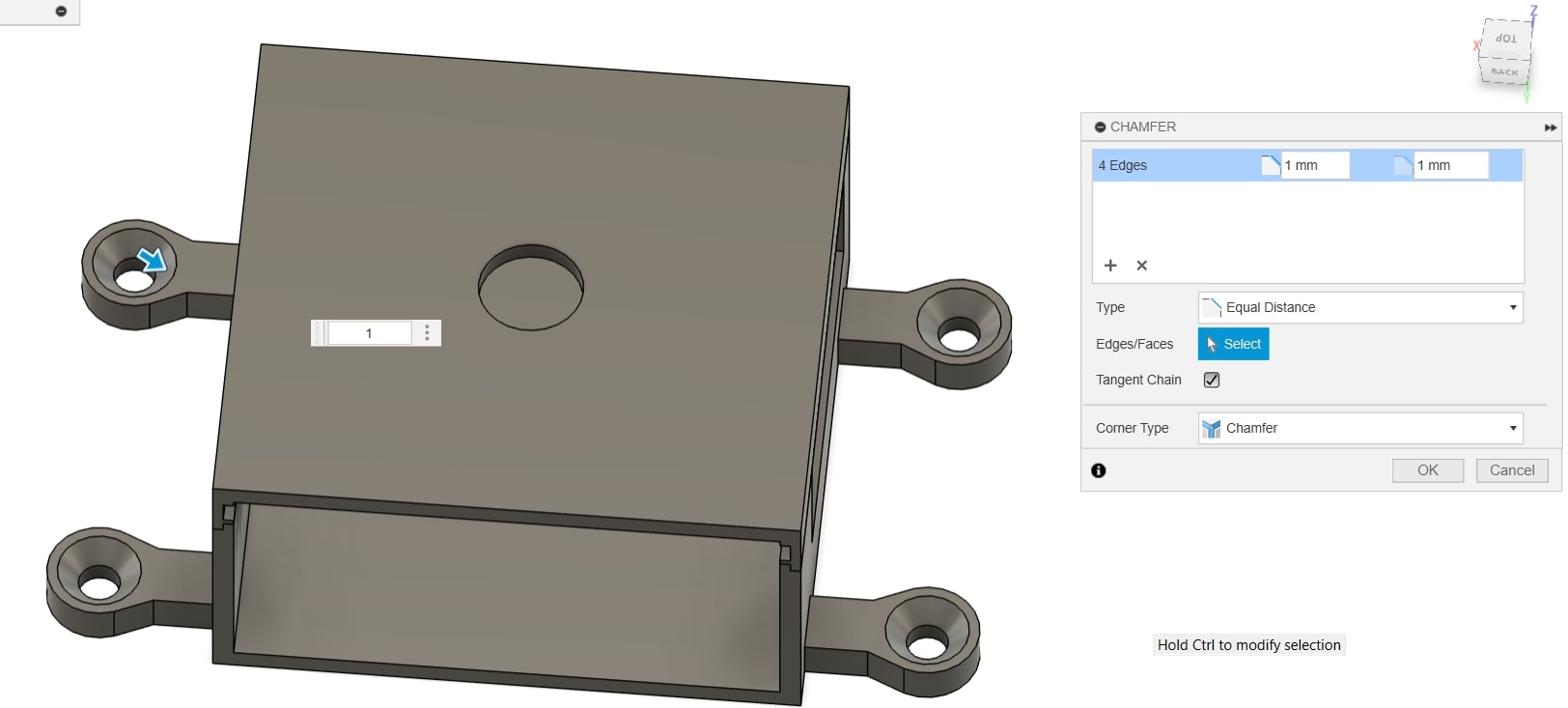
Lastly, I added few 5 mm fillets around the box to enhance the visual
appearance.
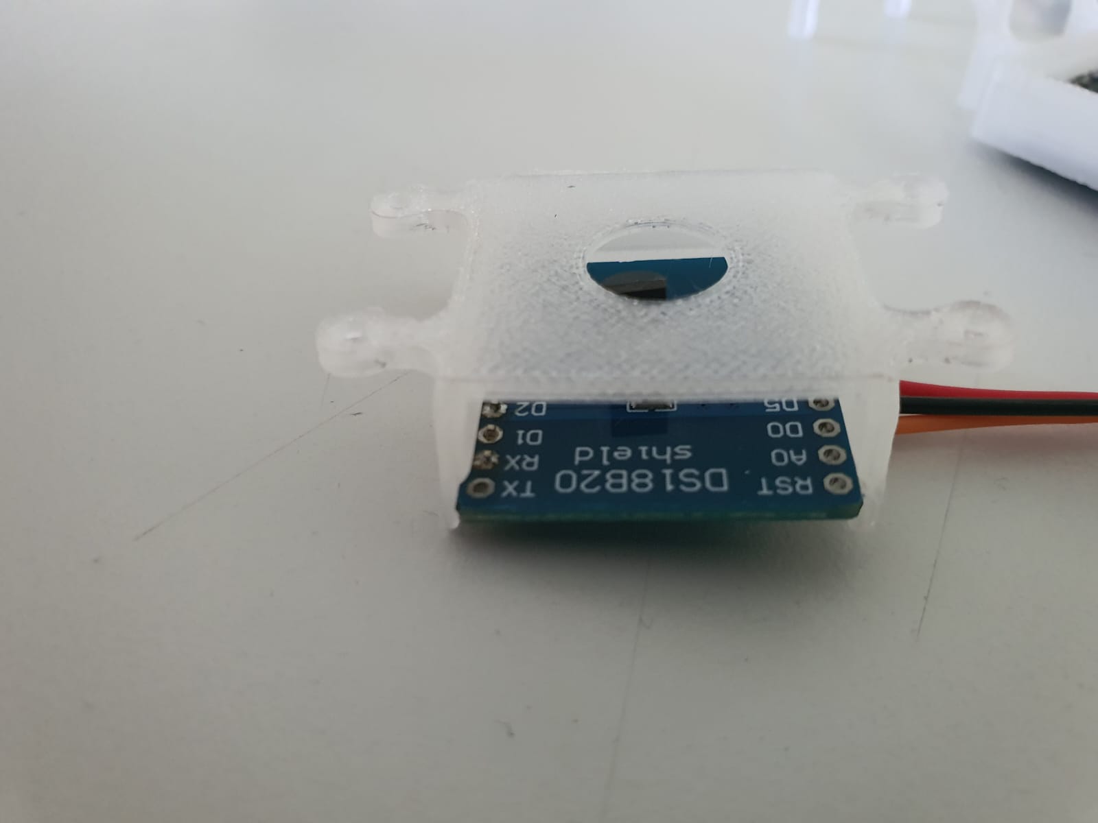
Designing the DS18B20 Temperature Sensor Housing
Using the the measured dimensions of DS18B20 Sensor, I drew a center
rectangle and extruded it to 13 mm in order to fit the the
sensor surface area.
Similarly to previously explained (extrude box + shell), I created a channel with
chamfer to slide the sensor shield into.
However, I decided to have it completely opened from the bottom so I cut
out completely the face. Since I need the sensor to be exposed and mounted
upwards to sense the heat coming from my PC for my final
project, I cut out a 10 mm circle.
Additionally, to consider the clearance of the pinheaders on the side of the shield, I
cut out ~ 1 mm into the wall of the box.
To be able to mount the box, I added four ear like extenstions on each
side, where a cut outcircles for screws and added chamfers
to compensate for the countersink of the screws.
Moreover, for each stress point as previously explained, I added 2 mm
fillets between those ears and the box itself.
Lastly for aesthetic purposes, I added 3 mm fillet around the upper edges
of the box.
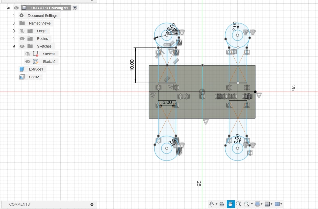
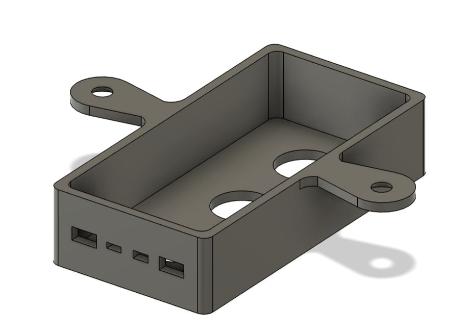
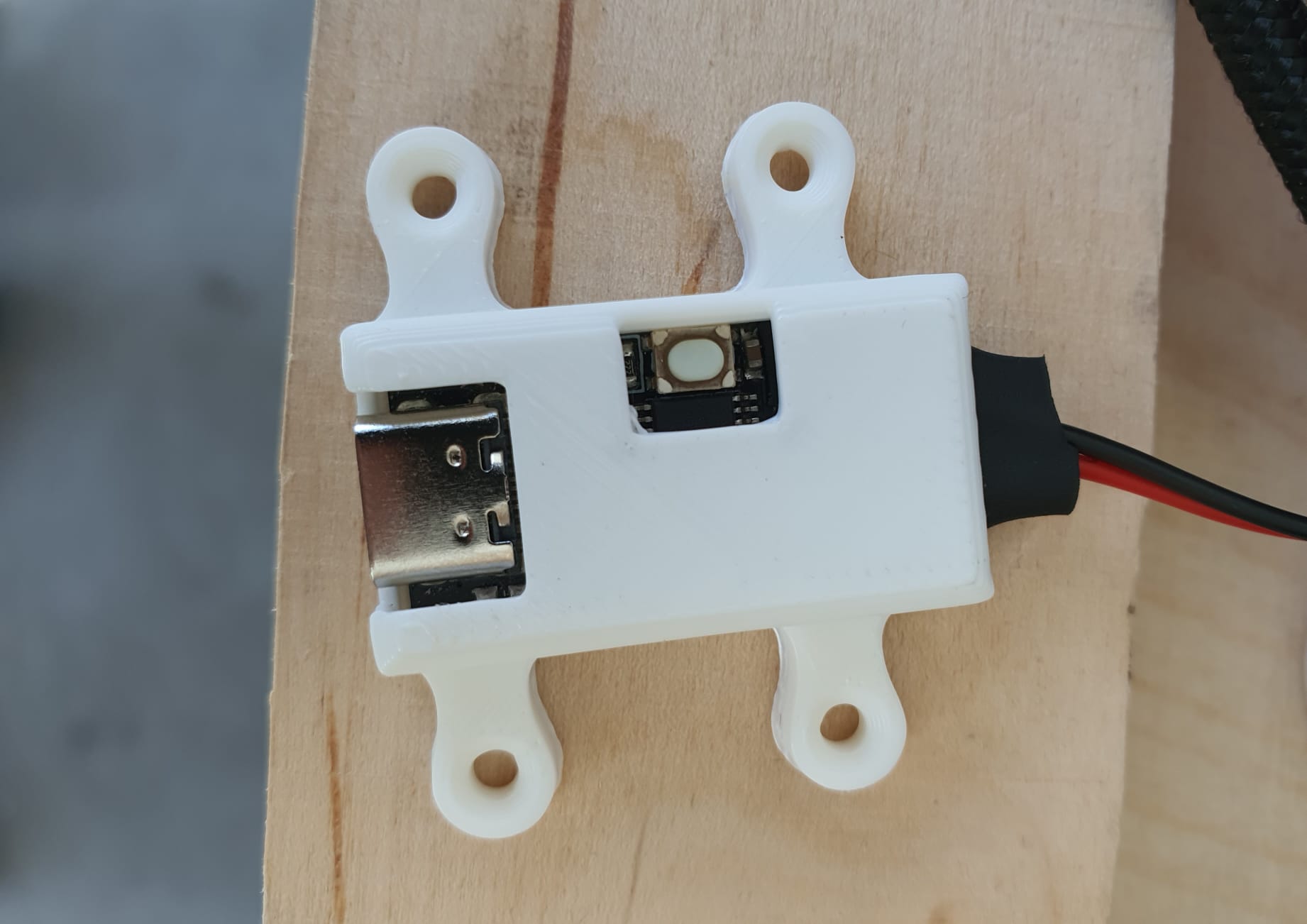
Designing the USB-C PD Module Housing
Using the measured dimensions of my PD module, I drew a center rectangle
and extruded it to 10 mm in order to fit the USB slot and the reset button
on its surface.
Similarly to previously explained (extrude box + shell), I created a channel with
chamfer to slide the module into. In order to be able to plug the usb, I cut
out a rectangle 3 mm * 8 mm from the back side of the box.
Furthermore, I created a lid to fit the other side of the box, with a cutout
rectangle 10 mm * 2.5 mm for the cables to pass through.
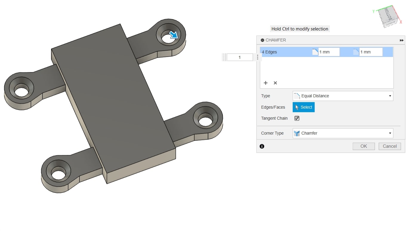
To be able to mount the box, I added four ear like extenstions on each
side, where a cut outcircles for screws and added chamfers
to compensate for the countersink of the screws.
Moreover, for each stress point as previously explained, I added 2 mm
fillets between those ears and the box itself.
Lastly for aesthetic purposes, I added 3 mm fillet around the upper edges
of the box.
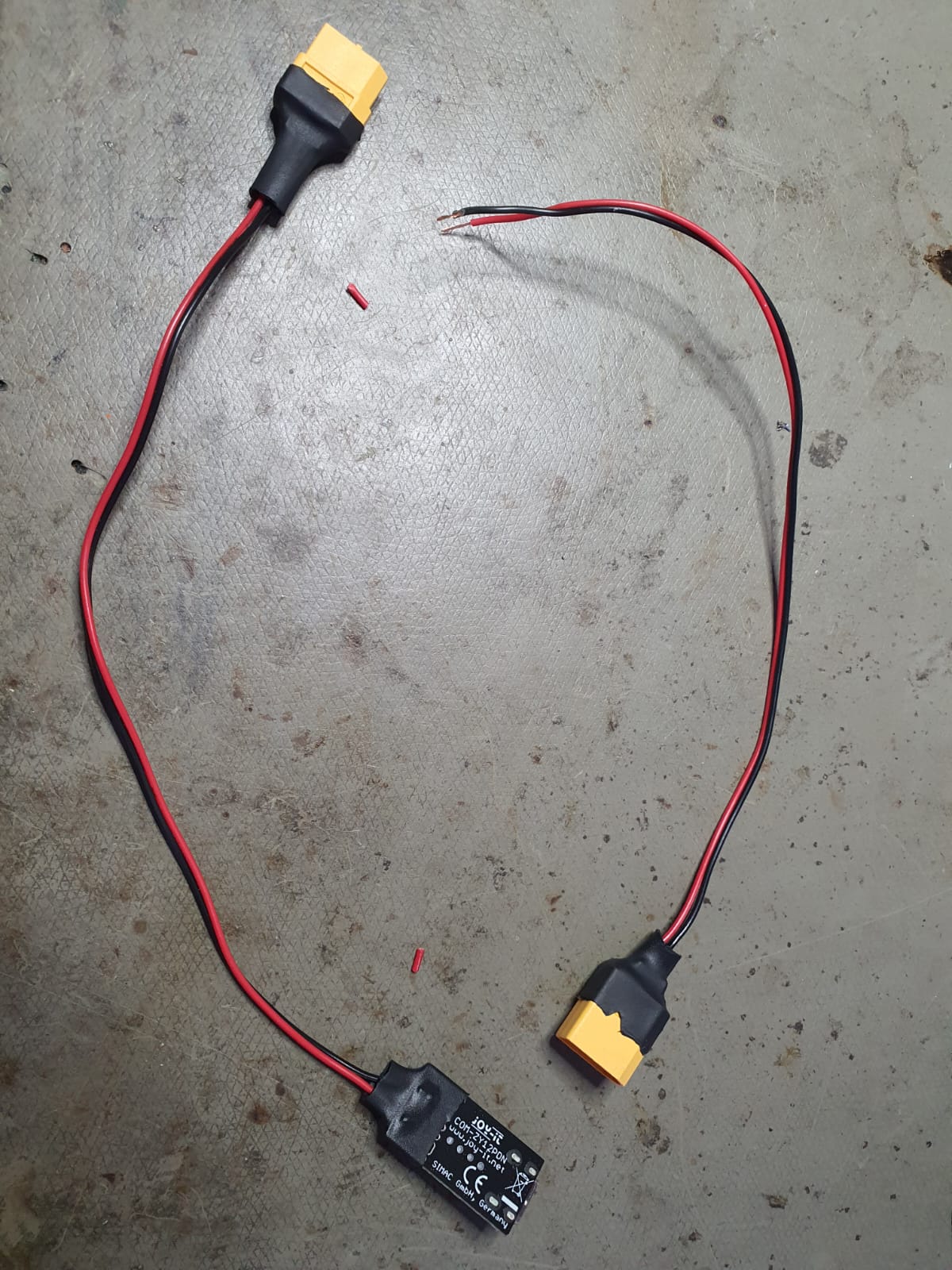
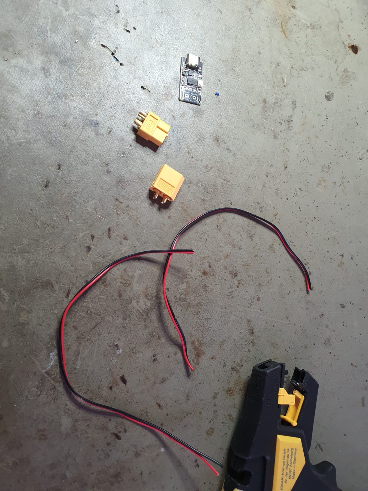
Cable and Connector soldering to USB PD Module
To integrate the PD module to the system, I had to solder some connector (negative and
positive), to be able to connect it to the power bank. Hence, I used two
TX 60
connectors, which have maximum current input of 60 A. It is not requred to go that
high, but that was the only available ones in the lab.
As fot the cables, I looked up the
American Gauge Wire table, and I found the 0.8 mm diameter ones that I will use,
which have perfectly maximum current load of 1.5 mA (also safety limit).
In order to insulate the cables well, I used Heat shrink, which are "closed
tape like" material that would shrink when heated with the hot air gun. This in turn helps
release the stress from the soldering points into the the shrunk heat!
Now to set the voltage mode distributed by the PD module, I referred to the datasheet,
I followed step by step in order to make my default mode: 12V.
Then, I tested my whole circuit integrated with both the PD module and the powerbank;
everything worked as intended!
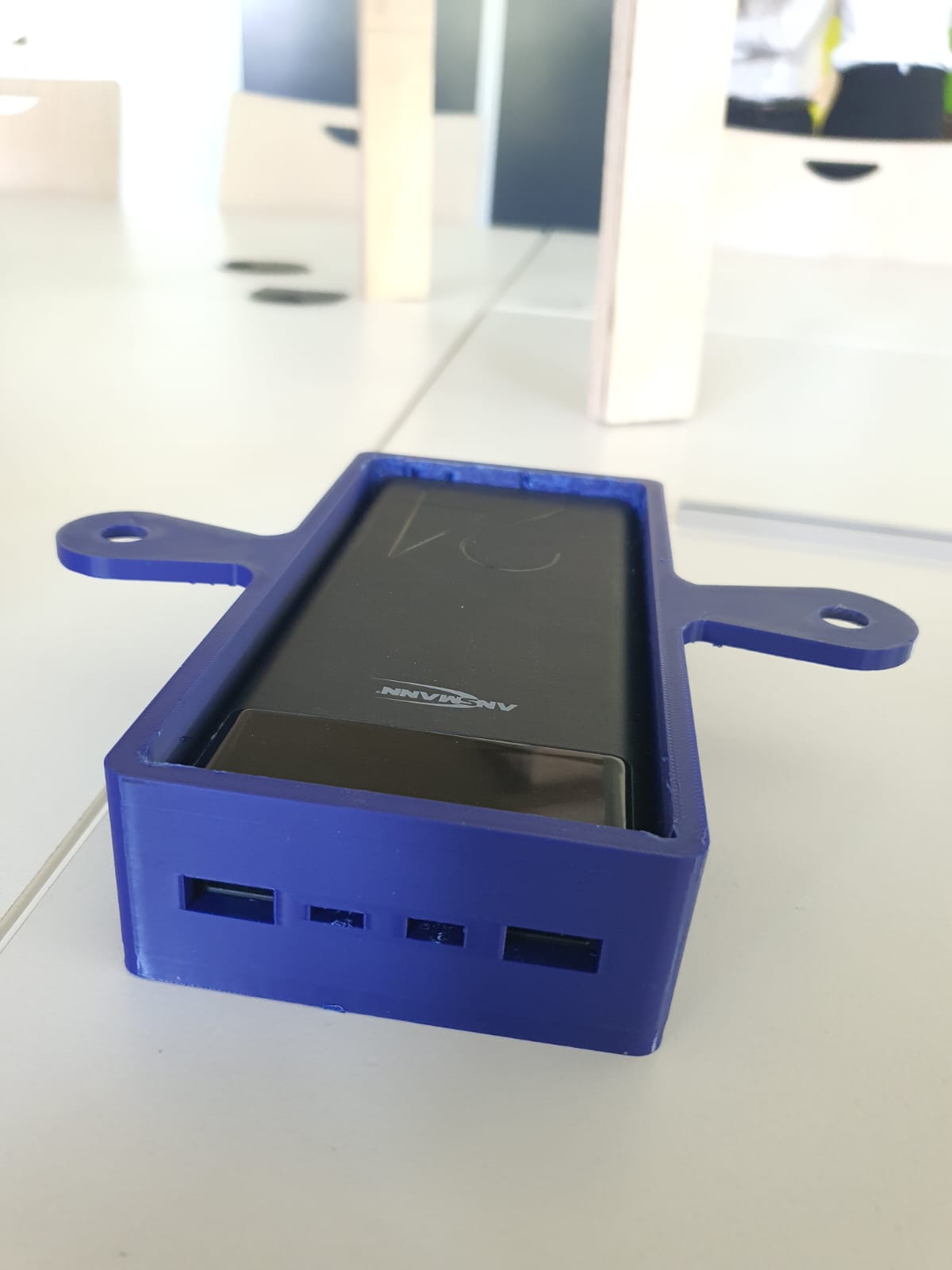
Designing the Power Bank Housing
Using the measured dimensions of my PD module, I drew a center rectangle
and extruded it to 39 mm the power bank.
Using shell tool I created an open box. In order to have the the USB slots
accessible, I decided to measure each USB slot and cutout each one of the and have that face
closing like a lid (New body).
To fixate the lid, I extruded into the wall a 1 mm deep rectangle and I
added a chamfer for easier insertion. I created a mating part on the lid
itself.
To be able to mount the box, I added two ear like extenstions on each side,
where a cut outcircles for screws and added 5 mm chamfers
to compensate for the countersink of the screws. To size down the hole, I designed a washer
with the same thickness of the ear and projects the mating part of the chamfer-hole cut out
of the ears. Now a screw of 4 mm diameter should fit!
Lastly for aesthetic purposes, I added 5 mm fillet around the edges of the
box.
Final Designs of All Electronics Housings
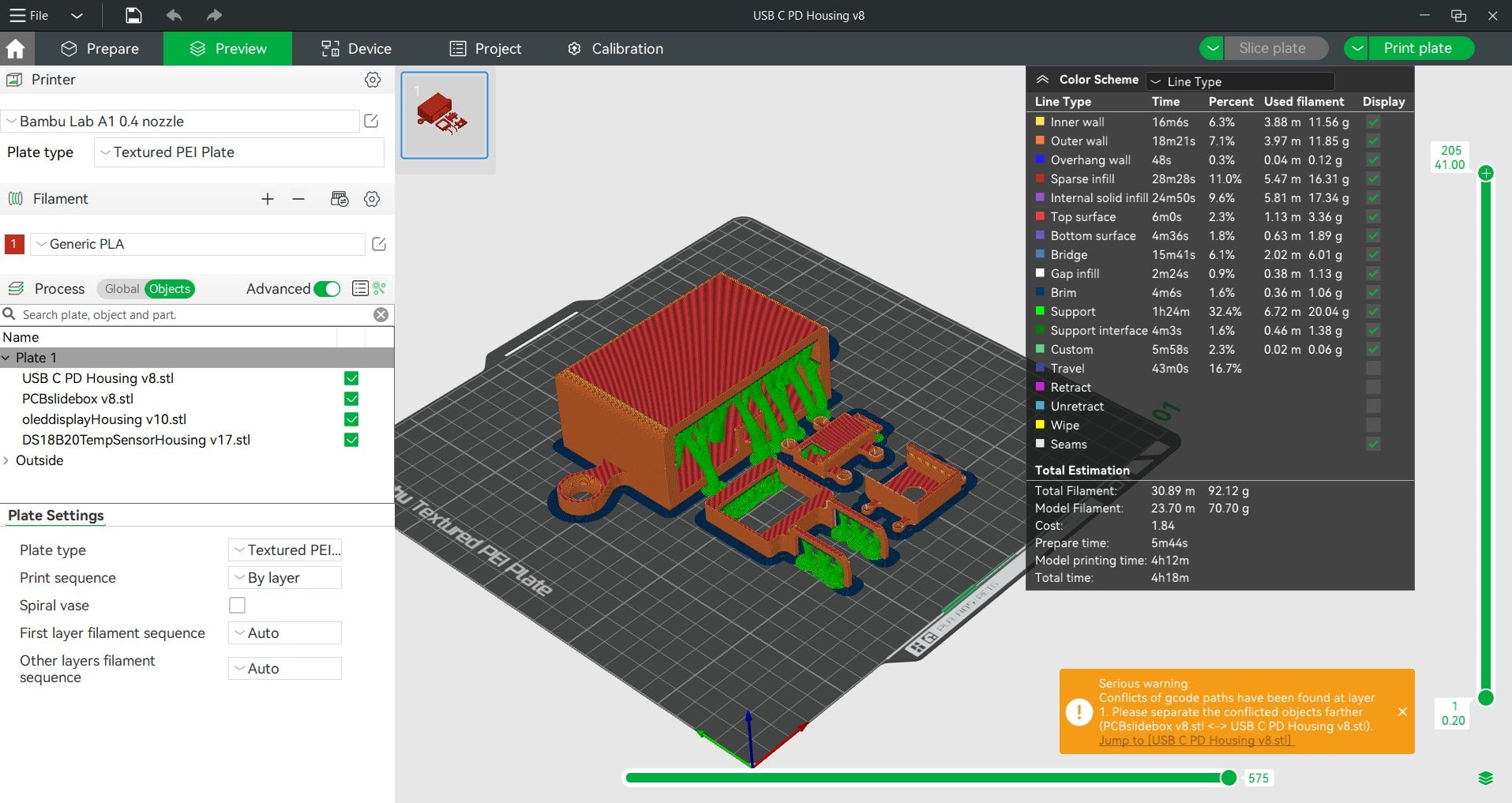
3D printing Housings for Electronics
I sliced the housings .stl files on the Bambustudio. I set the support type to tree
(auto), and the brim type to outer brim only. I left the
default settings to those of the Bambu Lab A1 0.4 nozzle.
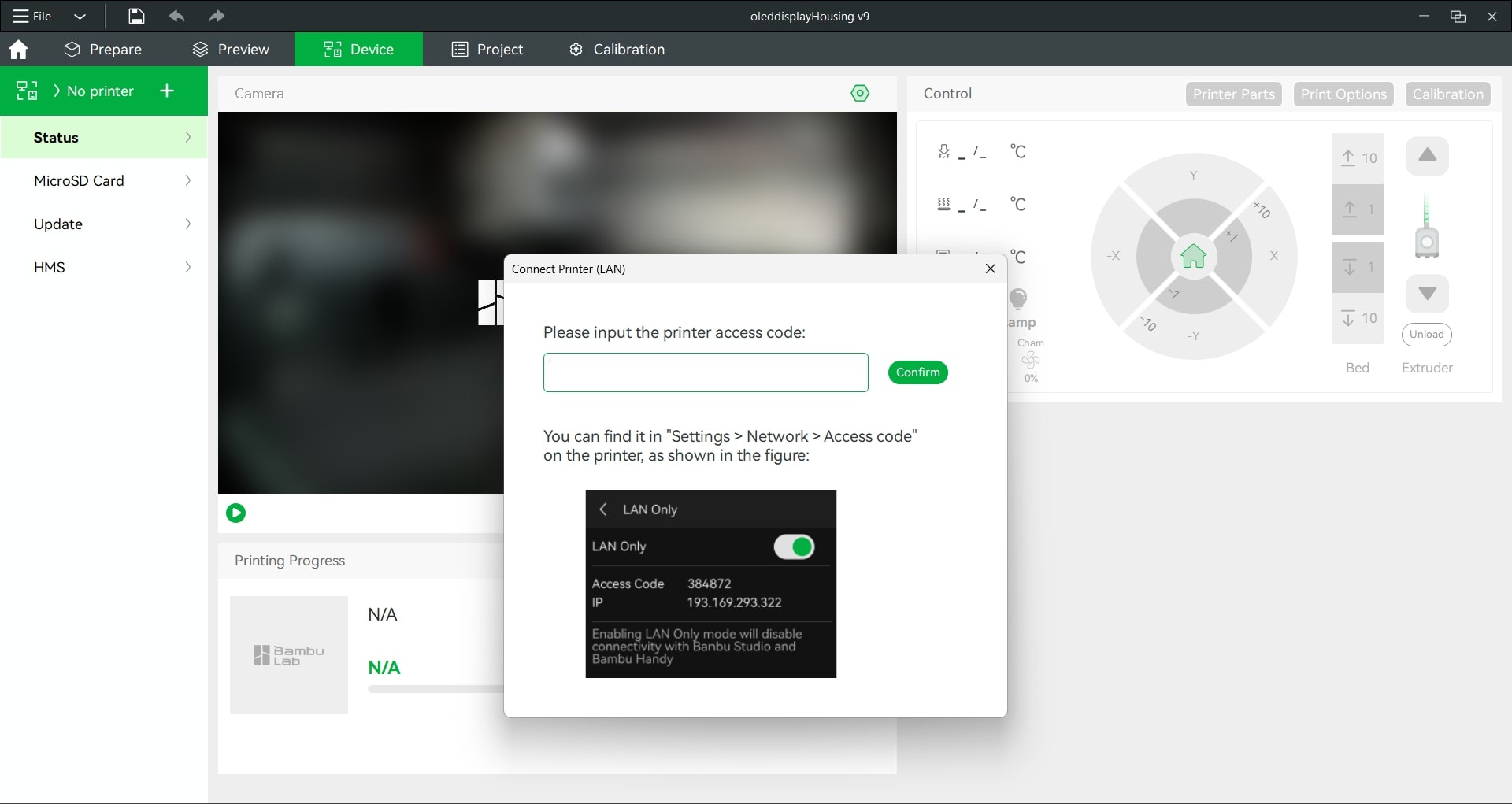
Nevertheless, this time I tried something different; I sent the sliced g-code over
WLAN by scanning and for available devices, selecting the right device and
adding the access code to connect to the printer.
Before clicking sending, it is always good to double check that the
printer's bed is empty and no calibration strips from the filament are left. Once confirmed,
I sent the job. The whole first test print took ~50 min.
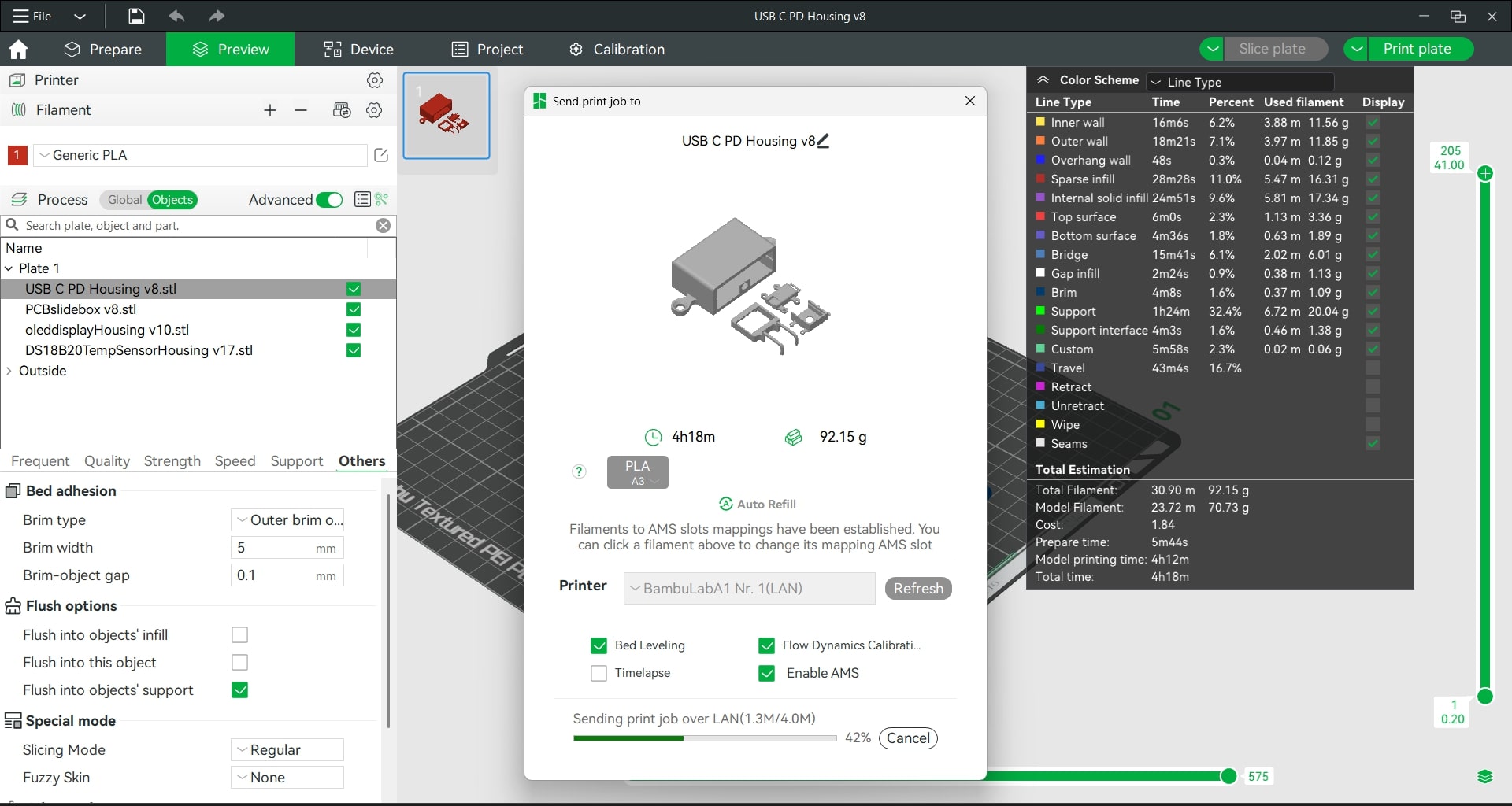
One more cool thing is that I was able to watch the print right from my laptop's screen,
which is very convenient while needing to use the time to document B)!
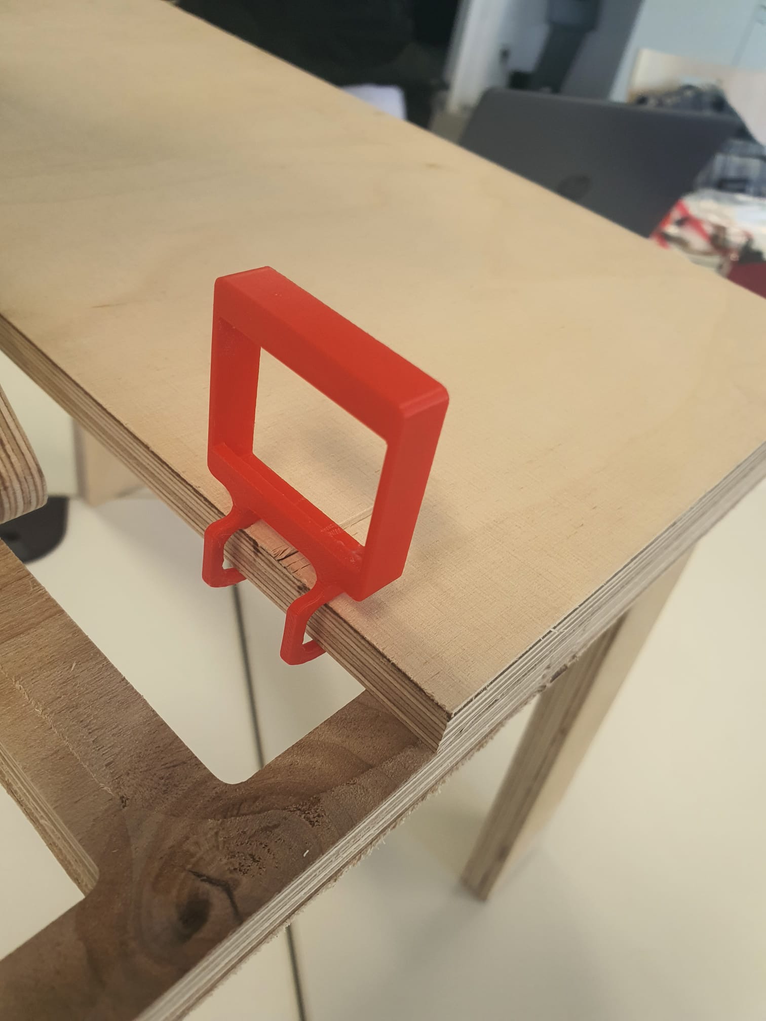
The second test after confirming that the hook fit perfectly into the 12mm plywood
thickness.The channels I created for sliding each component also worked perfectly. The only
thing that I modified was the cutout circle for the temperature sensor
doubled it in area.
Lastly, I just adapted the width of the hook so it fits both the table
surface and the rail base (12 mm + 15 mm). Once I have the updated table version ready
designed and cut, I can easily adapt that dimension fo the hook to fit accordingly.
I used the same Bambu A1 printed to print all four housings: USB C PD module, PCB,
OLED03.1 display, and DS18B20 temperature sensor. The printing this time took
~4 h 18 min.
Assembly for Each Electronic Component + its Housing
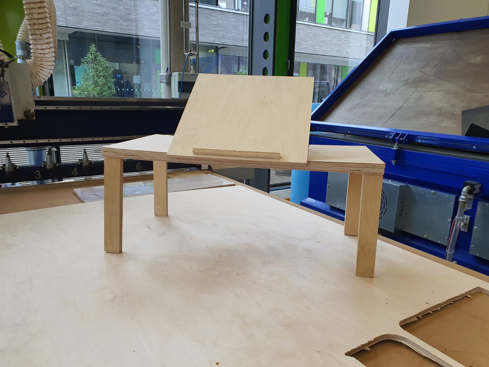
Mechanical Components
For my laptable, I used the one I already cut in Week
7 - Computer controlled machining.
This was my intention for this week: to complete the first spiral and push it as far as
possible, and if I still have time I can cut my updated table design again and integrate all
the other components accordingly.
Determining PWM range for my Actual Fan
Finally, my fan arrived, so I wrote a simple code to determine the minimum and the maximum
PWM range to map the speed fan accordingly (voltage input)
                                        /*
This code is to find out the PWM mapping range (min, max) for my fan
*/

const int FAN_PIN    = 16;    // PWM pin to fan MOSFET/gate

void setup() {
  Serial.begin(9600);
  pinMode(FAN_PIN, OUTPUT);
}
void loop() {
  for (int p = 0; p <= 255; p++) {
    analogWrite(FAN_PIN, p);
    Serial.print("PWM = "); Serial.println(p);
    delay(500);         // give the fan time to respond
  }
  while(1);            // stop after one loop
}
As you can see in the video, the fan starts to rotate with the PWM
value hits 170. Hence, I changed it accordingly in my final
project (draft) code - week 11!
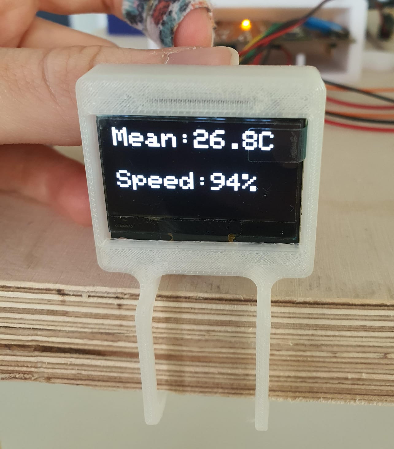
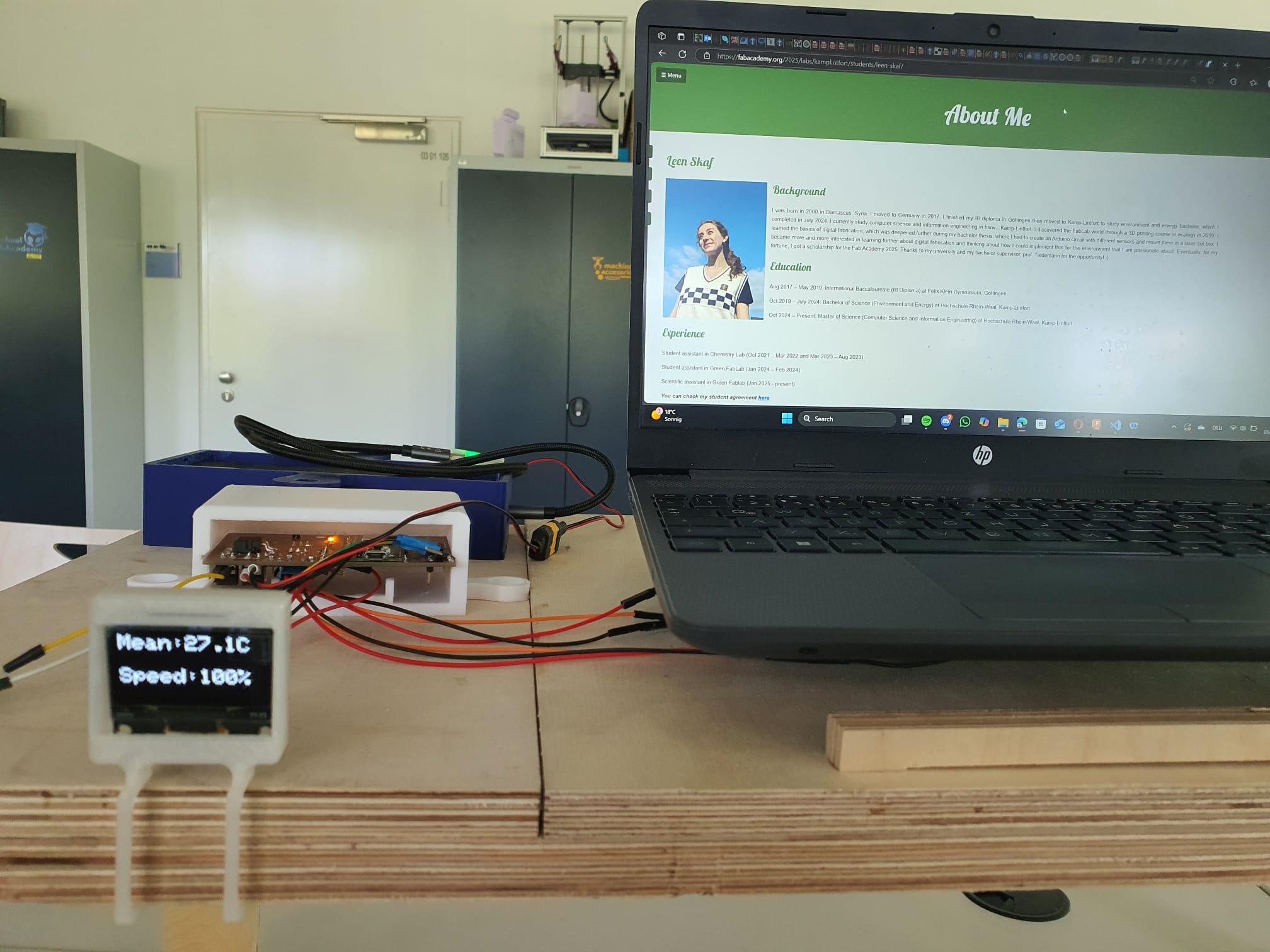
System Integrating Test
In order to proceed with mounting everything on my table, especially my temperature sensors,
I went ahead and did another benchmark test like how I did in Week
9 - Input Devices.
I placed a tape in the middle of the table, roughly where my CPU heats the maximum, then I
placed my temperature sensors inside and put my laptop on top of the tape. Afterwards, I
observed the values of the mean temperature and the fan speed rising slowly until it hit
100%.
This confirms for me where I can drill two rectangle cut outs into my table surface to play
my DS18B20 sensors flushed. The rest of the system (the PCB, PD module, and the power bank)
will be placed at the bottom left corner on the left side of the plate. The OLED display
will be mounted using the clamp also on the left side (since I am right-handed).
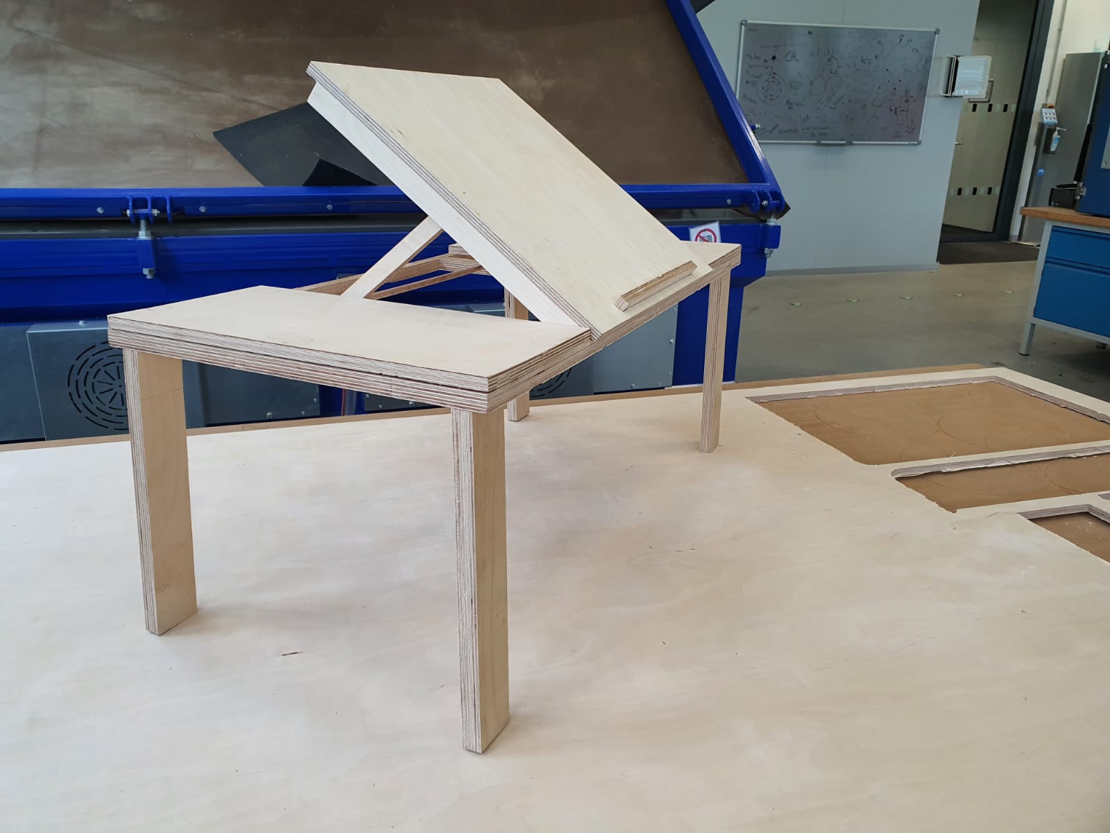
In order to pass the air flow from the fan to the laptop, I also cut out "pattern" in the
middle section of the table. As for mouting the fan, since it should be blowing in the same
direction as the fan of the laptop is blowing in, I placed it under the surface with a ~ 45°
angle .
Mounting Components, Laser Cutting, and Cable Management
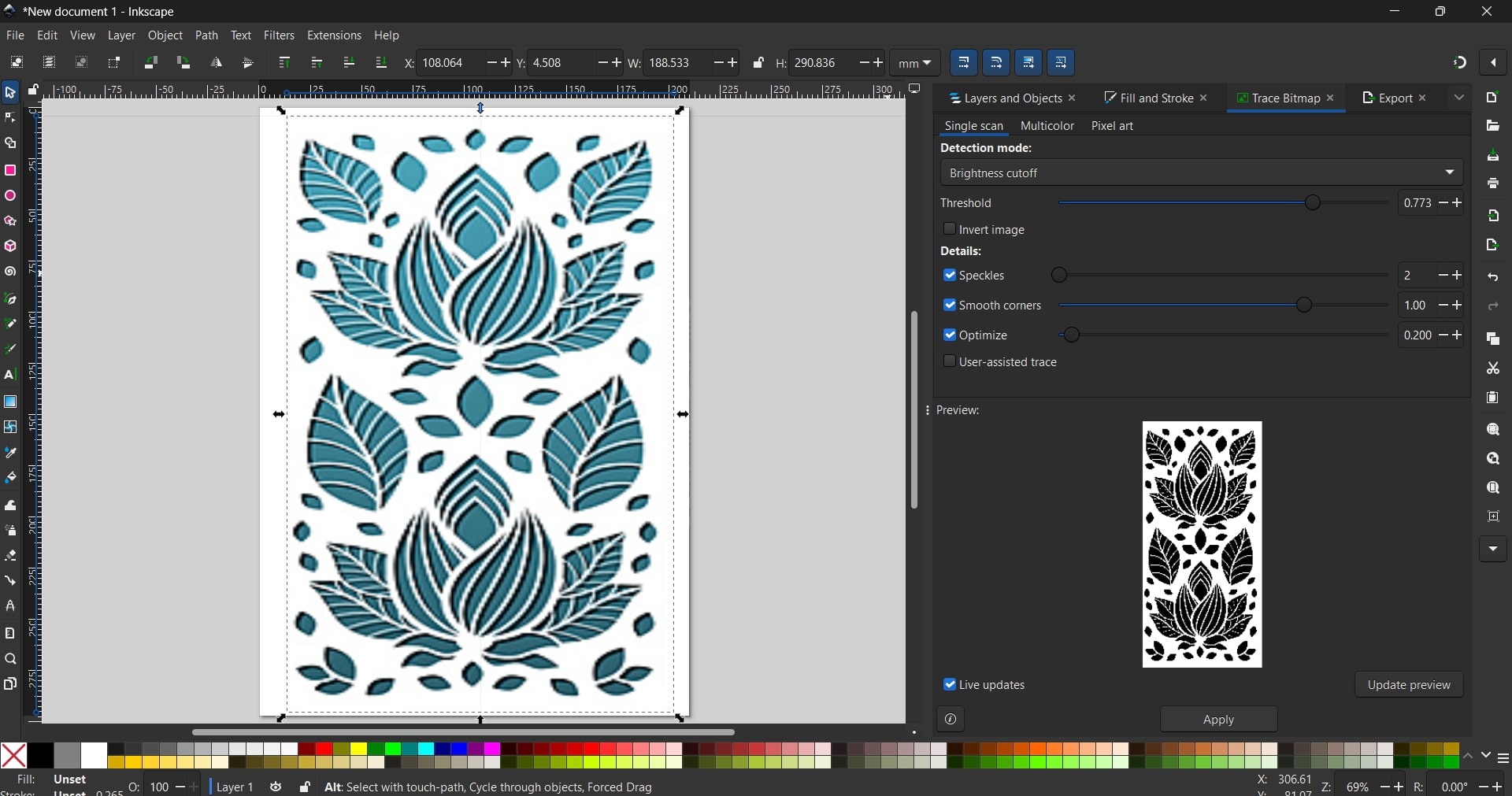
In order to have hide nicely the cutouts for the sensors, I found this tree
pattern to engrave in the middle section of my table.
First, I downloaded the .png file and I used Picsvg
converter to convert it to an .svg file. Then, I went to inkscape to apply trace
bitmap in order to see the contrast (black and white) where the pattern will be
engraved on the table.
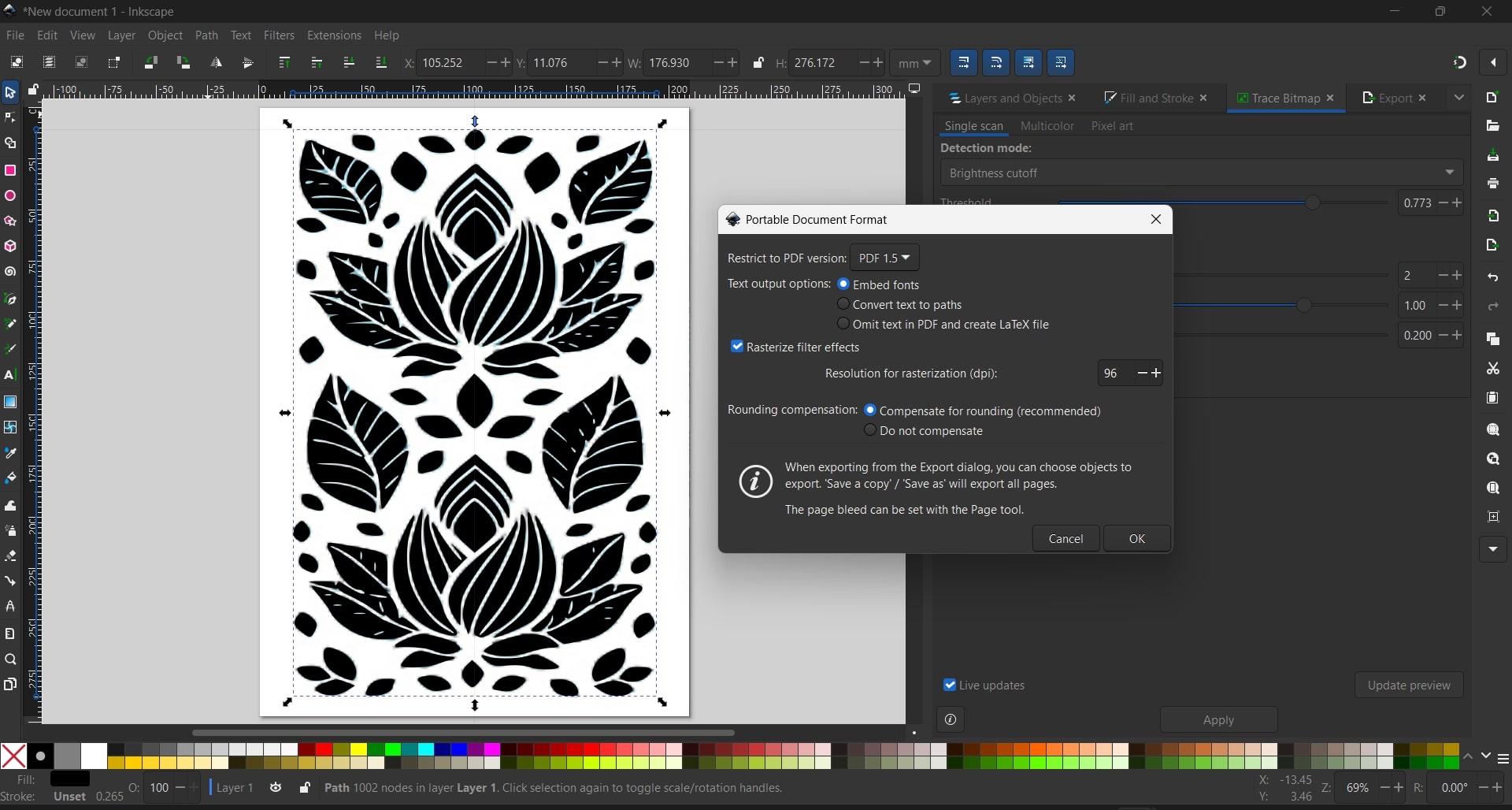
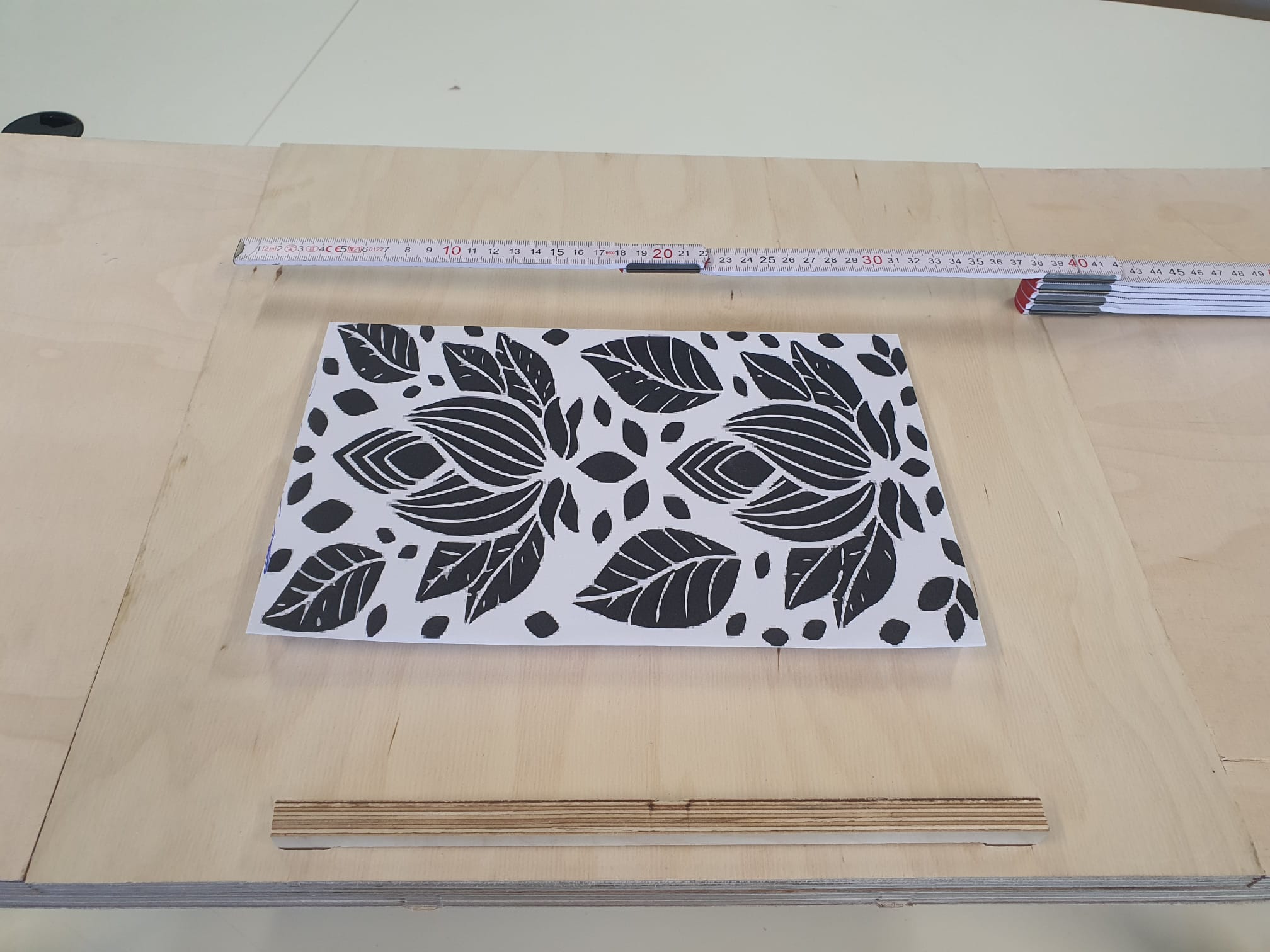
Once I scaled it to A4 paper, I exported it as a pdf and printed it on an
A4 paper. Then, I placed it physically on the table and measured exactly the dimensions
where I want it to be. The dimensions where ~ 265 mm × 170 mm. Then, I measured where
the laser head has to exactly jog it there manually and start the engraving job.
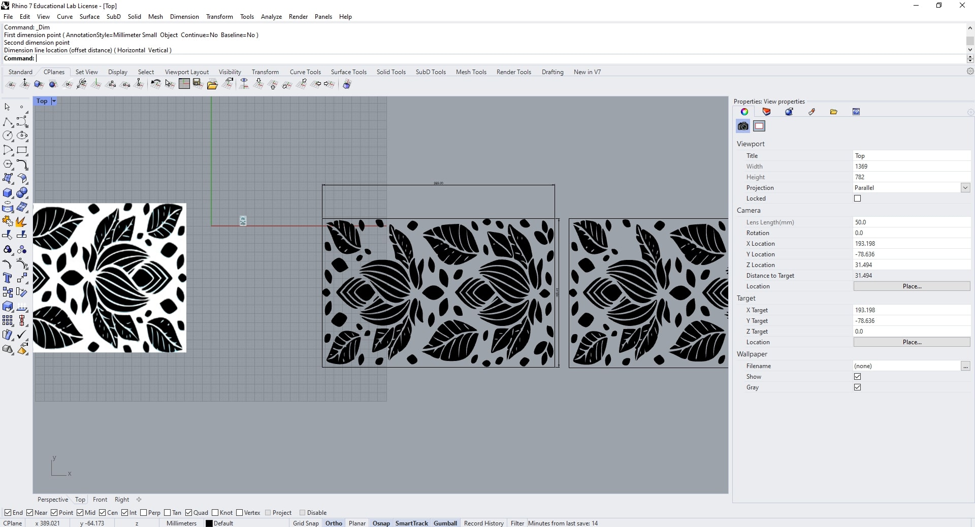
Afterwards, I went to Rhino 7 to manipulate
the pdf file and exactly fit it to the dimensions I previously measured.
Now, with the shortcut ctrl + p, I went to the Epilog Dashboard software,
and I set the engraving parameters and I set the power to 60% and speed to
95%.
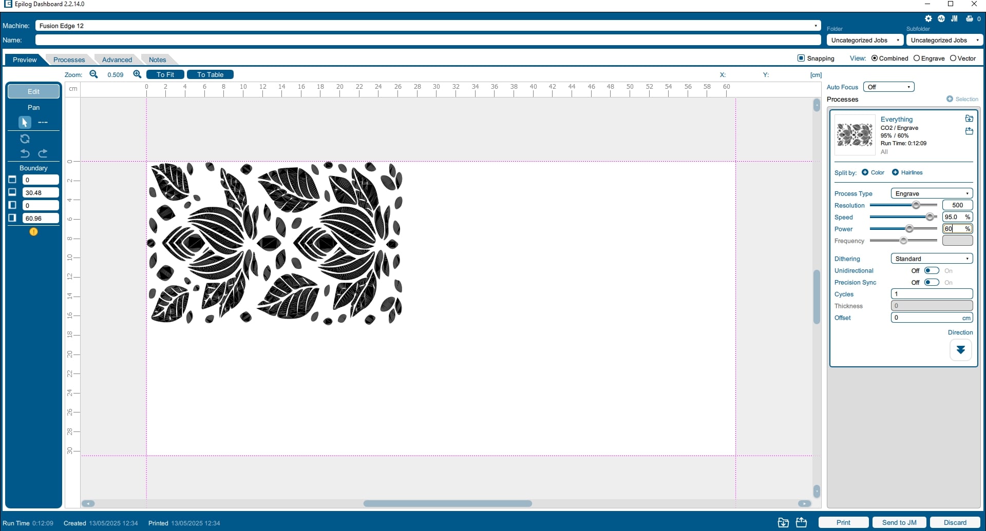
Lastly, I sent the engraving job to our Fpilog
Laser Fusion 60 Watts CO2 Laser, after I made sure that the laser head is exactly at
the upper left corner point of the pattern to be engraved.
The whole process took 17 min to finish.
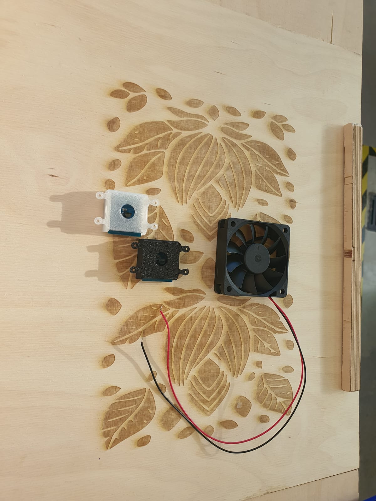
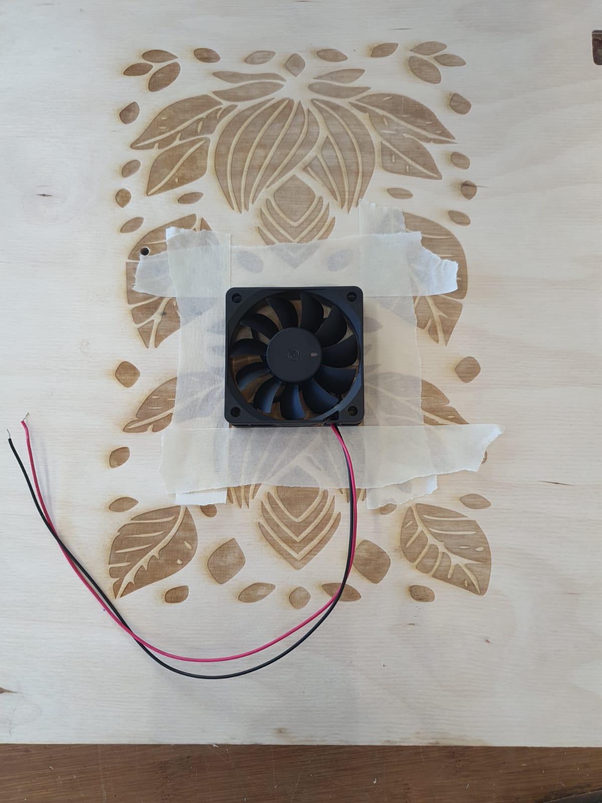
Mounting Fan and Sensors
First, I positioned the fans and the sensors where I measured the laptop gets the most
heated. Additionally, for the fan I positioned it under the sensors location alittle bit to
the left, so it is around the same positions where my laptops fan is to help aid the
original internal cooling mechanism.
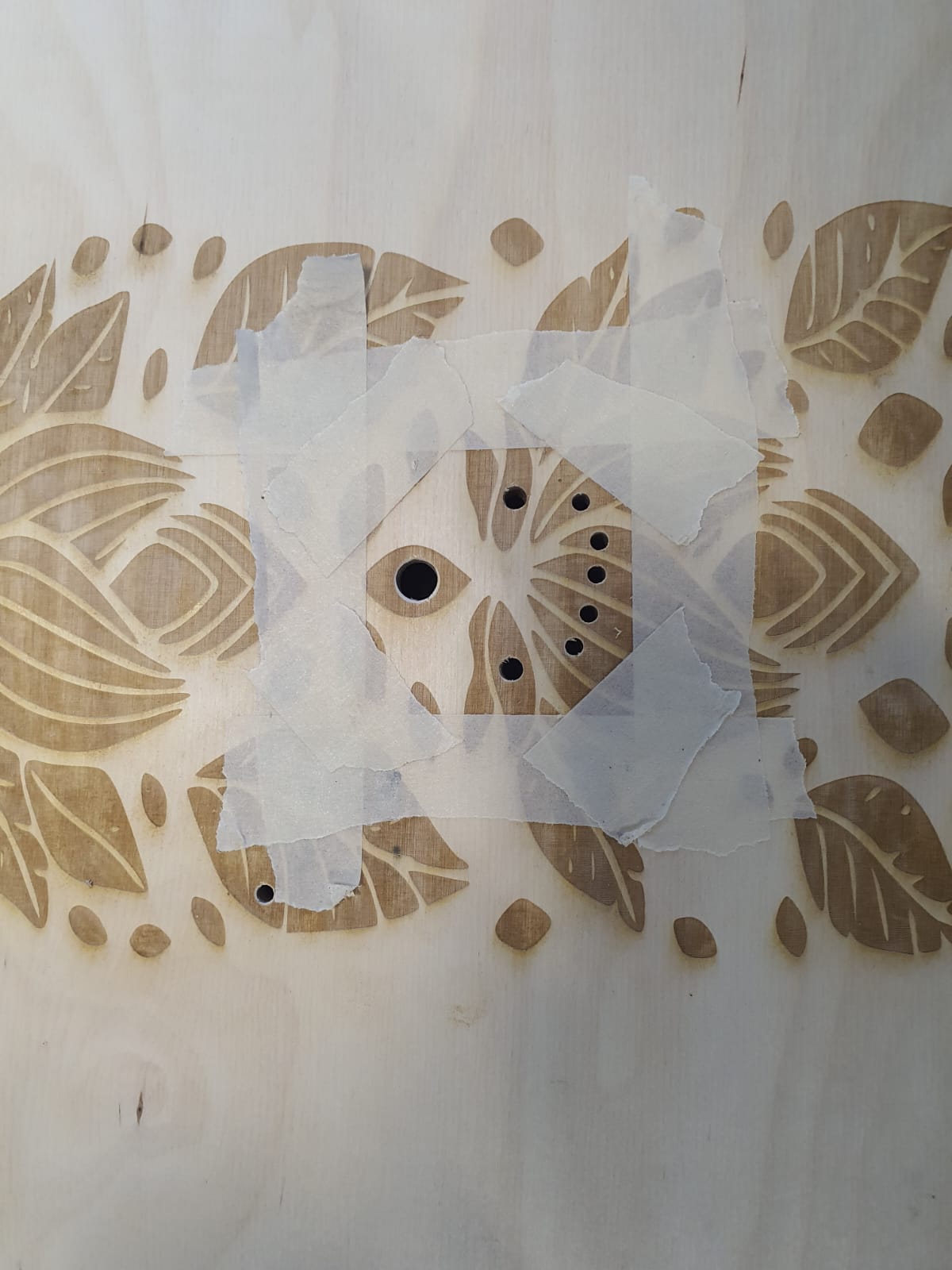
Then, with the help of my instructor, we drilled two holes with 4 mm bit
for the sensors
heads, in a way that is disguised within the petal engraving.
Similary with the fan, I tried to disguise it with another petal engraving and drilled 5
holes with4 mm bit, 2 holes with 5 mm bit, and one hole
with 8 mm bit.
In order to fix the blowout on the opposite side of the drilling, we went with the
countersinking bit (45° chamfer) for each drilled hole!
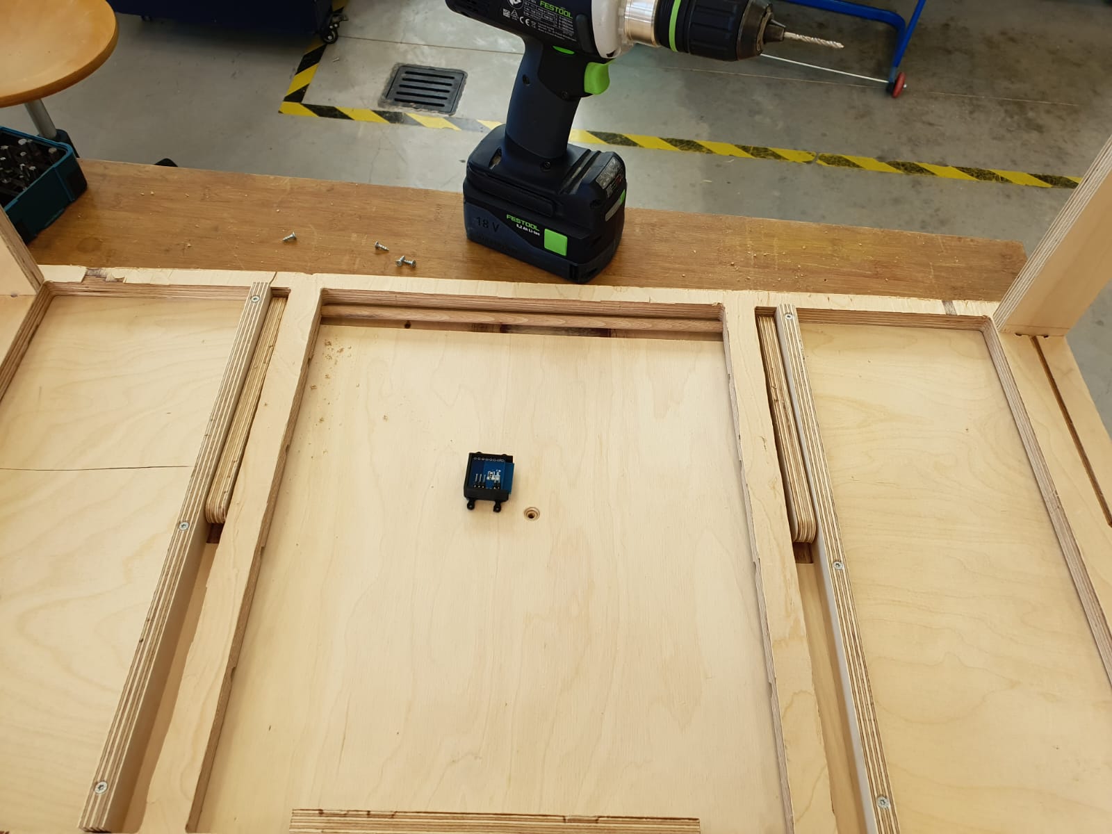
Now, I have both sensors and fan mounted and fixated on the bottom side of my table's
surface. The only thing to test is whether more cut outs are needed for a better airflow,
and whether blowing out to help the laptops fan dissipate the heat to the outside or blowing
into the laptop itself has a better cooling effect!.
After testing, we confirmed that the airflow going in the same direction of the internal fan
is decently impactful and aids in cooling. Therefore, we decided to commit to it and fixate
the screws all the way in.
Nevertheless, to have less of a distance between the fan and the table top surface, we
decided to laser cut a pocket with the same dimensions as the fan (60 mm × 60 mm
× 15 mm).
However, for the sensors, we decided to add some conductive material like brass or copper in
the holes to help transfer the heat faster. Moreover, I broght down the minimum thresholf in
the code for the fan to turn on to 22°C, so the speed of the fan reaches to
100% faster!
Conclusion and Reflection
This week was a very productive week! I 3D designed and printed housing for each components,
engraved tree pattern on my table surface using the laser cutter, calculated the overall
power consumption and determined the run time of my electronics circuit using my power
supply (power bank), tested my fan and mapped the PWM range accordingly (starting at PWM =
170),
performed a live system test to identify the laptop’s hottest zones and the optimal airflow
direction.
and lastly mounted three components of my
electronics, a.k.a the fan and the two sensors.
What remains is cable management and the final mounting of my OLED display,
PD module, PCB board, and power bank into their housings, potentionally adding conductive
brass inserts for faster thermal transfer at the sensor drilled channels,
continue redesigning my table for
another spiral, and hopefully test the quality of the whole system in terms of ergonomics,
usability and funtionality. Once weaknesses are determined, I will continue on iterating to
achieve a final product to my satisfaction, even if that means continue on the development
spirals after FabAcademy is over!
Files
- Electronics Housing Design: PCB Slide Box
- PCBslideboxv13.f3d
- Electronics Housing Design: DS18B20 Temperature Sensor
- DS18B20TempSensorHousingv17.f3d
- Electronics Housing Design: USB-C PD Module
- USBPDHousingv9.f3d
- Electronics Housing Design: OLED01.3 Display
- oleddisplayHousingv13.f3d
- Electronics Housing Design: Powerbank Housing
- Powerbankhousingv11.f3d