Computer-controlled Machining
Group Assignment
- Do your lab's safety training test runout, alignment, fixturing, speeds, feeds, materials, and toolpaths for your machine
Individual Assignment
- Make (design+mill+assemble) something big (~meter-scale).
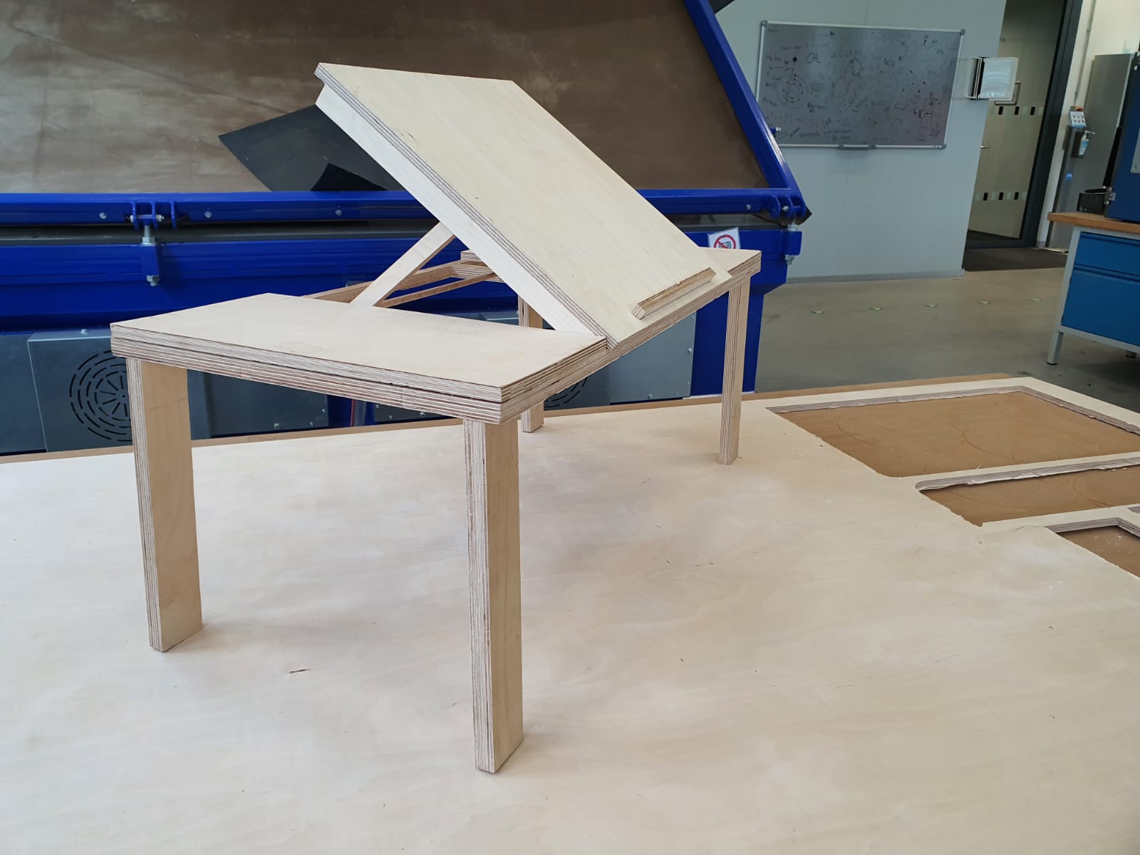
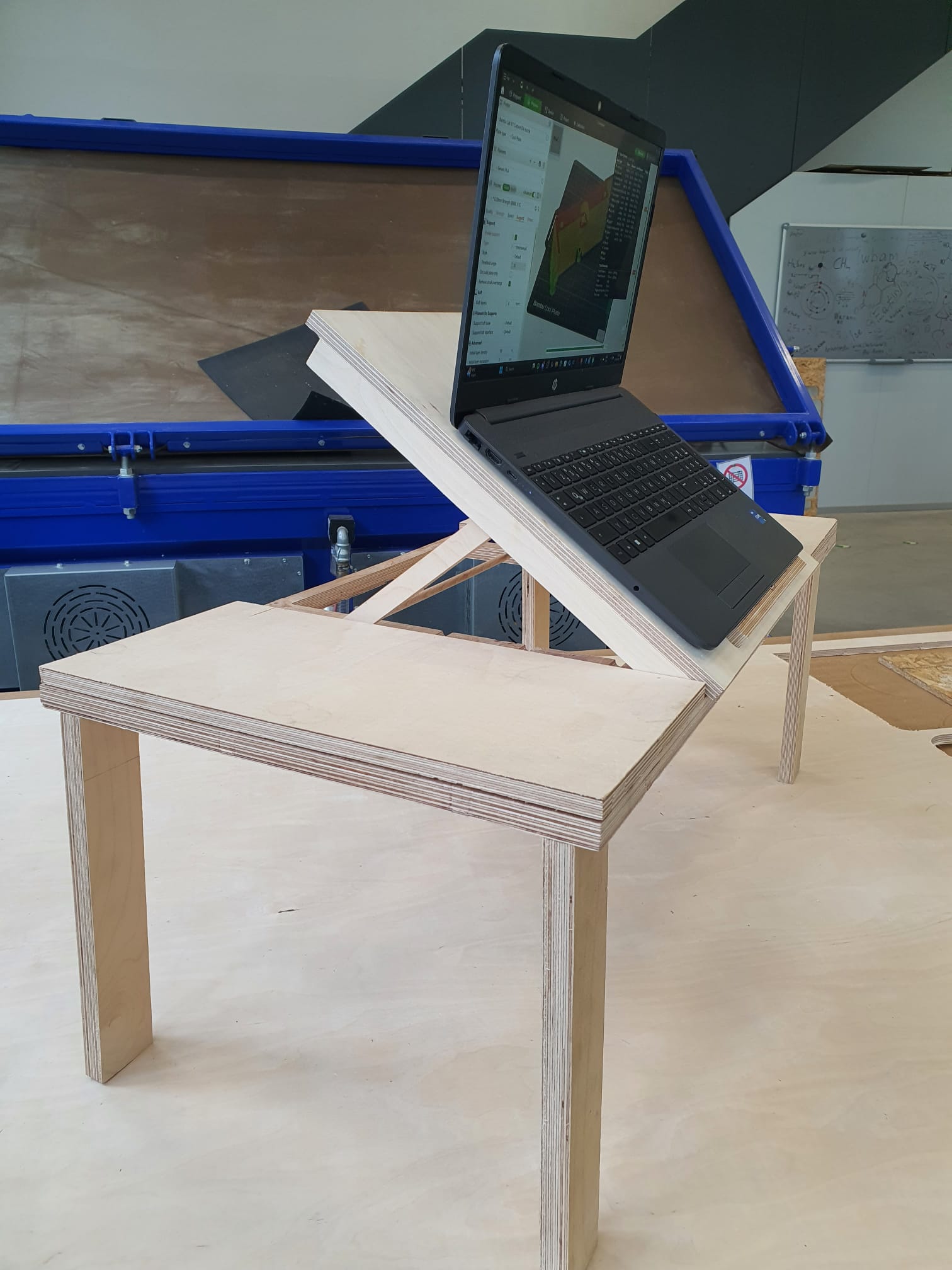
This week I started experimenting with designing bigger pieces (my lap table!) on Fusion360 to cut and mill.
Designing Table on Fusion360
I drew inspiration from an
adjustable artist painting board
that folds and locks at different angles, as well as
types of
joints
to create tight-fitting wood joints without screws or glue. Below is a step-by-step breakdown of
my design and assembly process.
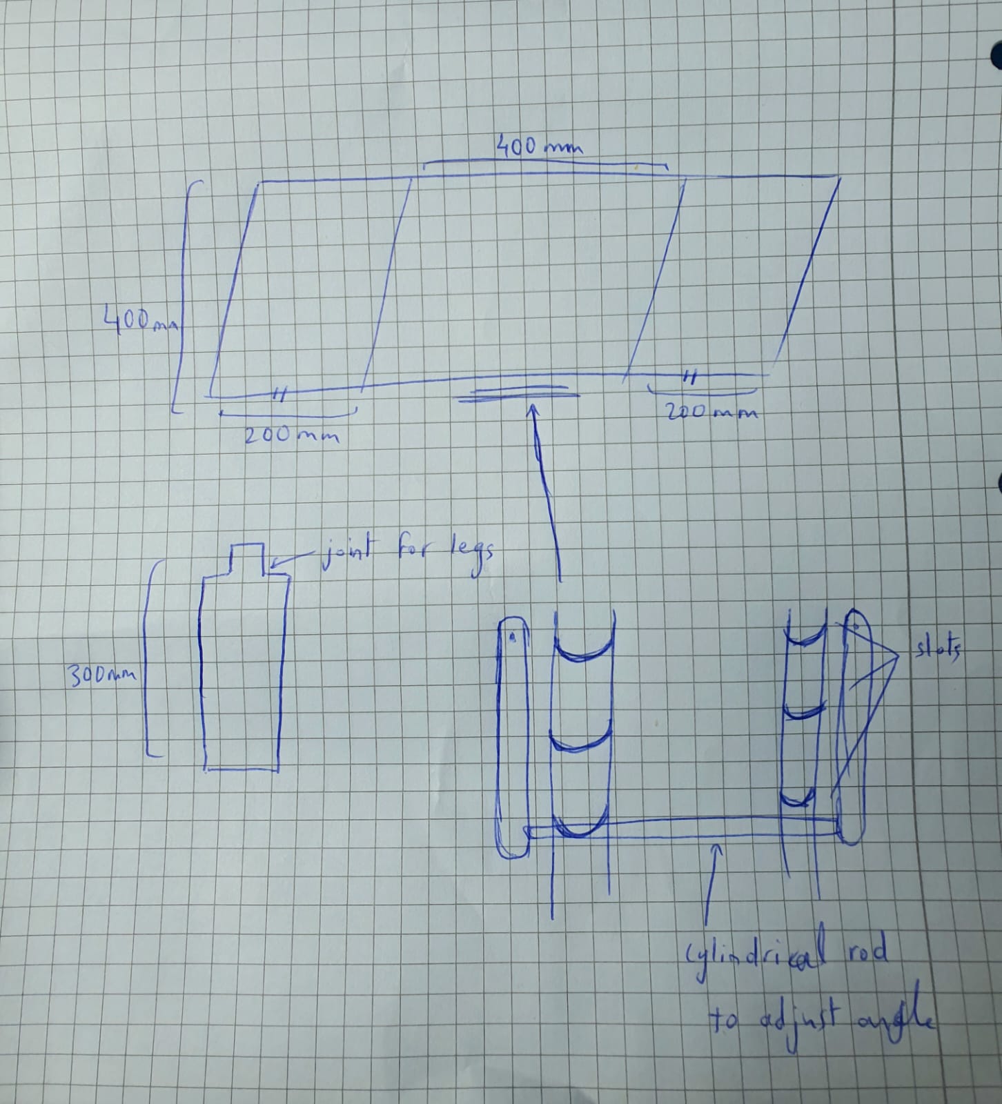
Planning and Sketching
I began with a simple hand-drawn concept, defining my table’s dimensions:
800mm (length) × 400mm (width) × 30mm (Legs height).
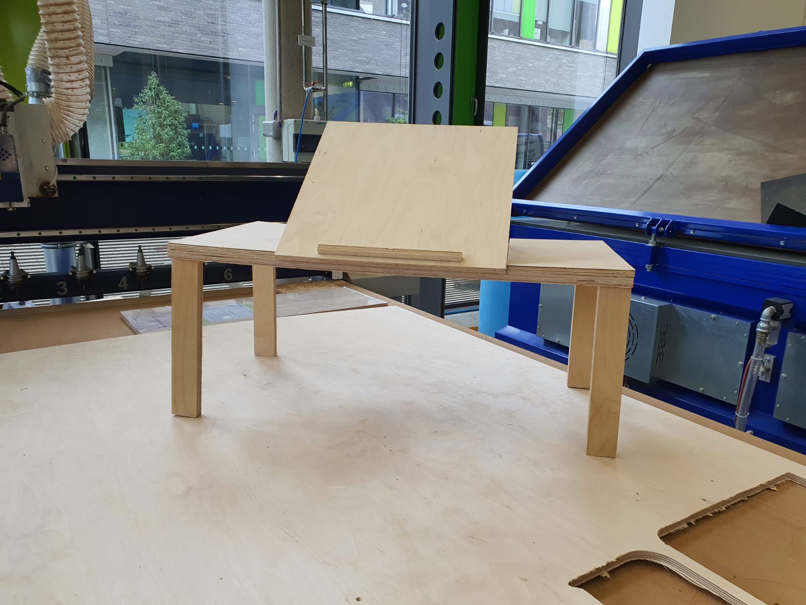
I wanted three sections on top: left and right fixed panels (200mm wide each), plus a middle
panel that could tilt for ergonomic use (400mm wide).
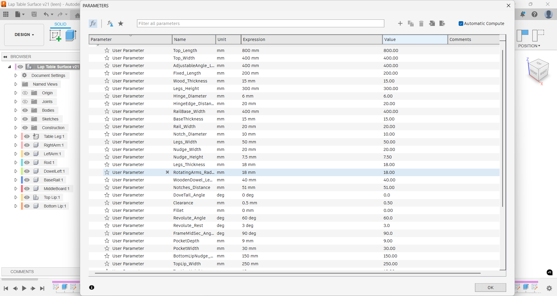
Adding parameters:
To ensure integrity throughout the process, I modified the necessary
parameters for all components.
Main Tabletop in Fusion 360
Creating a Sketch:
On the Top plane, I drew a rectangle
(800mm × 400mm) and extruded it to 15mm thickness.
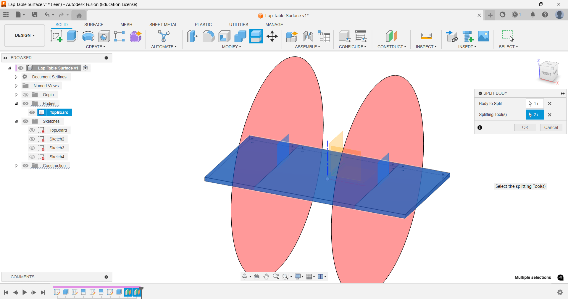
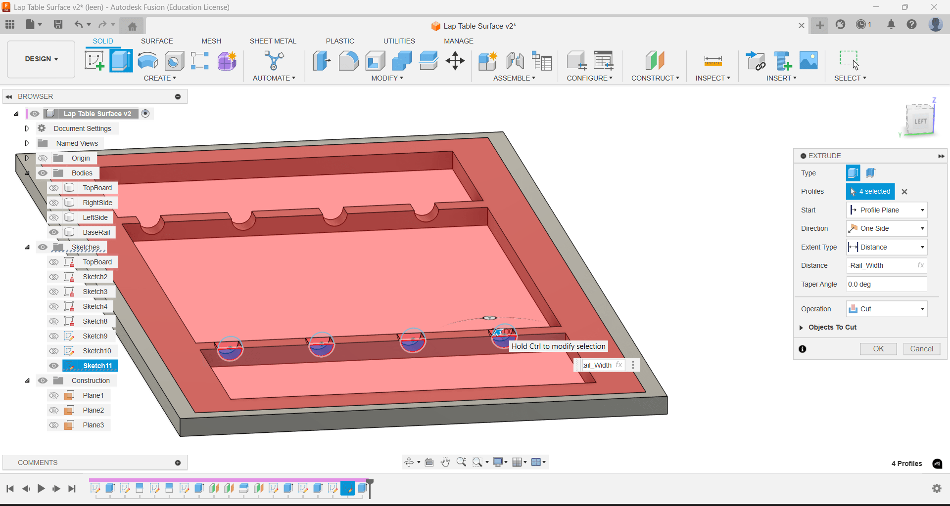
Splitting the Surface:
I used Split Face (and eventually Split Body)
to divide the tabletop into three sections (left, middle, right).
The middle section is where the laptop sits and hence has to be tiltable.
Adjustable Middle Section
Hinge Holes: Placed along the shared edge of the middle panel and the frame,
allowing me to insert a wooden dowel as a pivot for the rotatory rod.
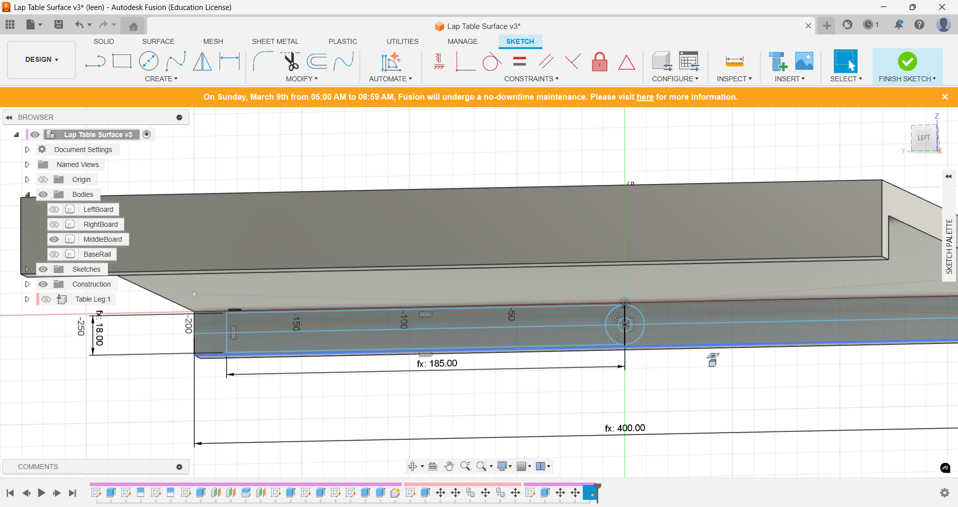
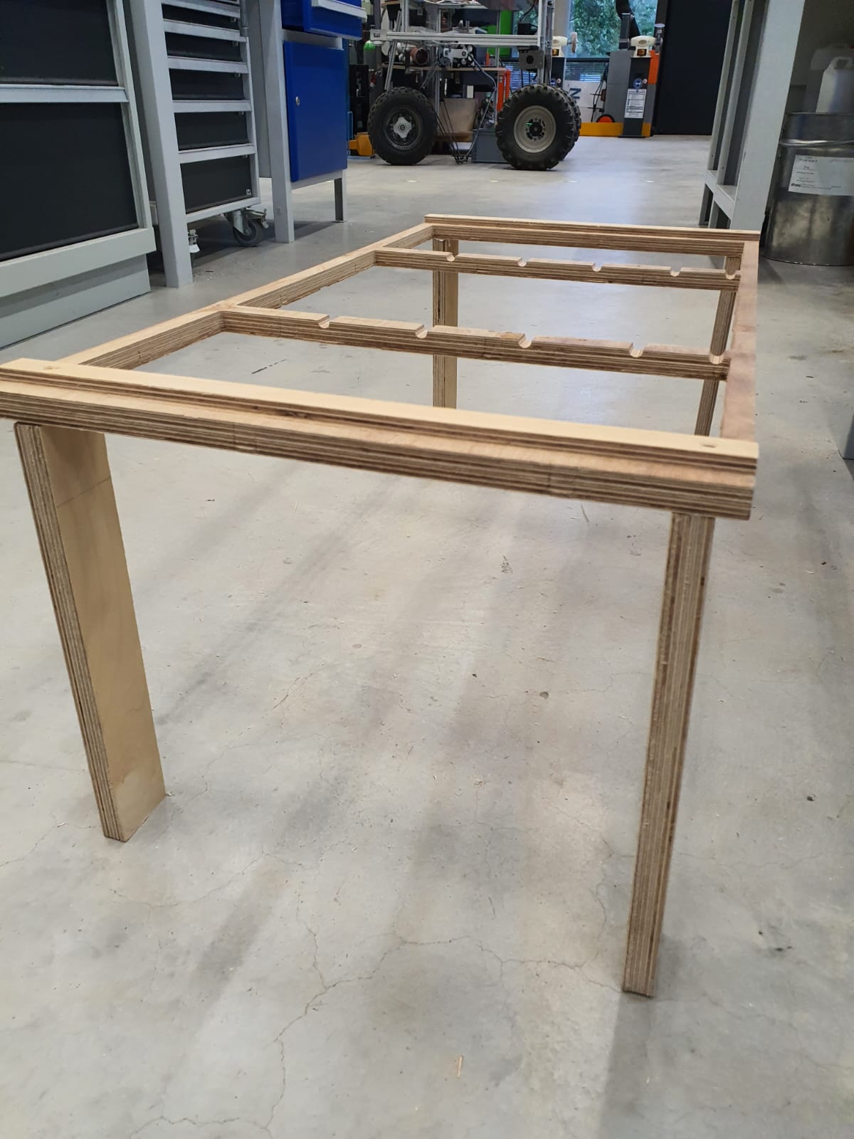
Frame, Legs, and Joints
Using ideas from types of joints:
Legs & Frame:
I modeled four legs (50mm wide and 300mm high), each extruded at 18 mm
thickness,
and a rectangular rail beneath the top for stability.
Support Arms & Rod Slots:
Wooden arms are extruded (15mm) on the inner frame of the middle surface,
where the pivot point is roughly in the middle of the arms.
A cylindrical rod connects the two arms, fitting into five slots on the rectangular rail,
locking the middle surface at various angles—much like an easel.
Top and Bottom Lips:
To create a pivot point between the frame and the table surface, I designed
a simple lip-like hinge.
This will be modified into a more stable mechanism in the upcoming spiral. Moreover, I added a
lip to the middle surface so the table does not slide when the surface is angled.
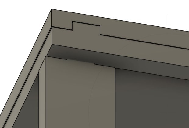
Dove Tail Joints:
Instead of screws, I implemented a half-lap **Dovetail Joint**, inspired by
Dovetail Half-Lap Joint. The joint is
20mm wide and 7.5mm high
(since the thickness of the material is 15mm, it is recommended to use roughly half of the
thickness as the depth of the joint).
This ensures a strong assembly without any screws or metal hinges.
Assembling in Fusion 360
Separate Components:
Each part (table sections, legs, rail, arms, dowels)
was turned into its own component by right-clicking on the body and selecting "Create New
Component from Body."
Name it meaningfully to reflect what each component represents.
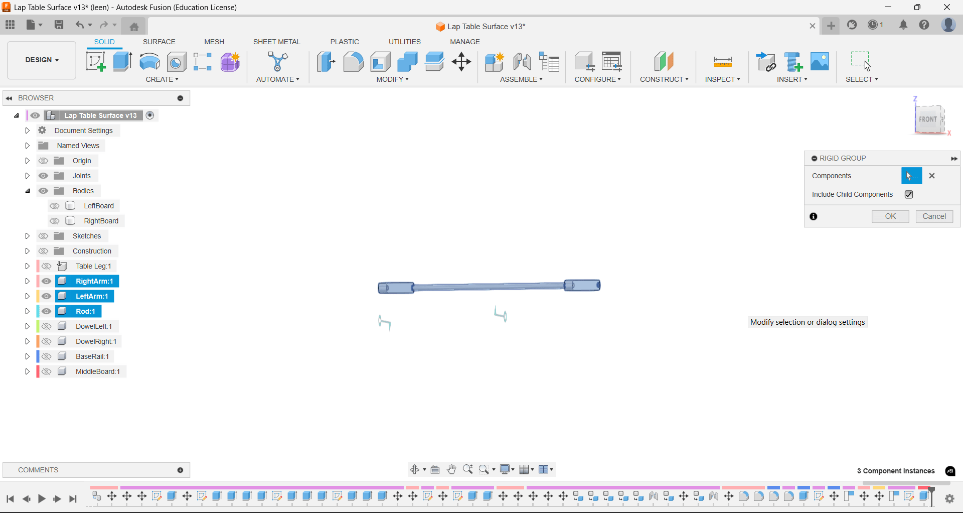
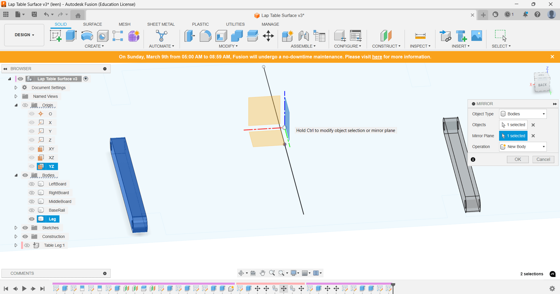
Joints:
I used Rigid Groups where components are treated as one
unified entity (rod with rod arms),
and Revolute Joints for the hinge (Lip) between the middle surface and the
frame and between the rod and the rod arms for adjusting the angles of the table surface.
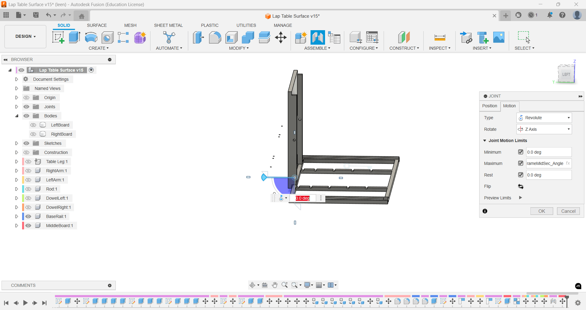
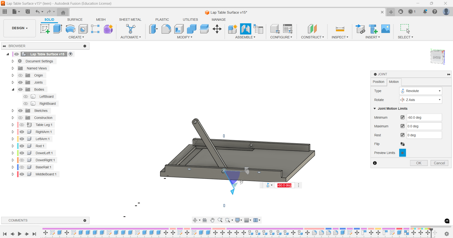
Motion Links:
By linking both revolute joints' movements, I managed to simulate the real
movement of the rod in real life.
Therefore, I can safely say that the mechanism will work in real life, allowing me to tilt the
middle section surface while the support arm locks it in place at chosen angles.
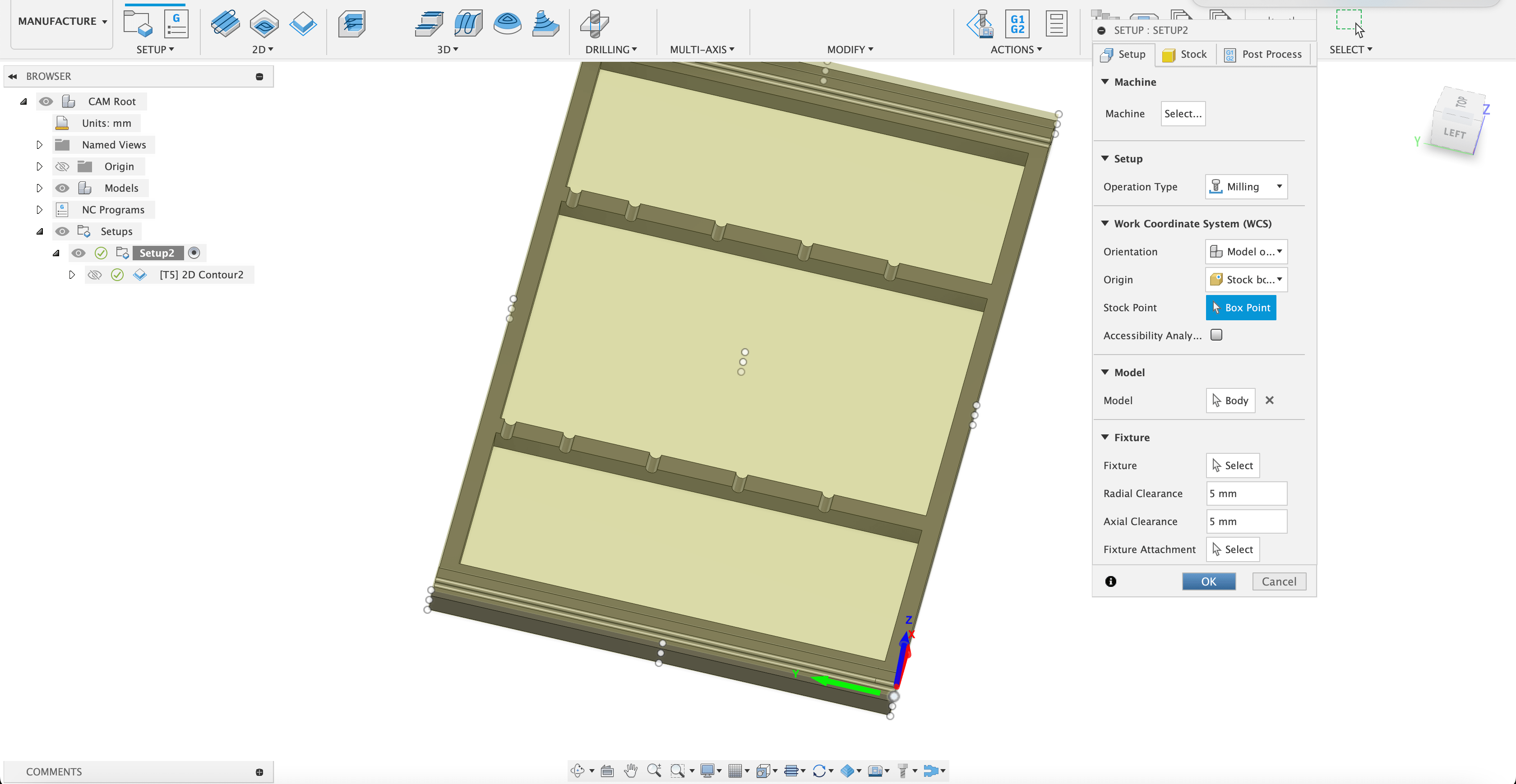
Computer-Aided Manufacturing (CAM) in Fusion360 Manufacture Workspace
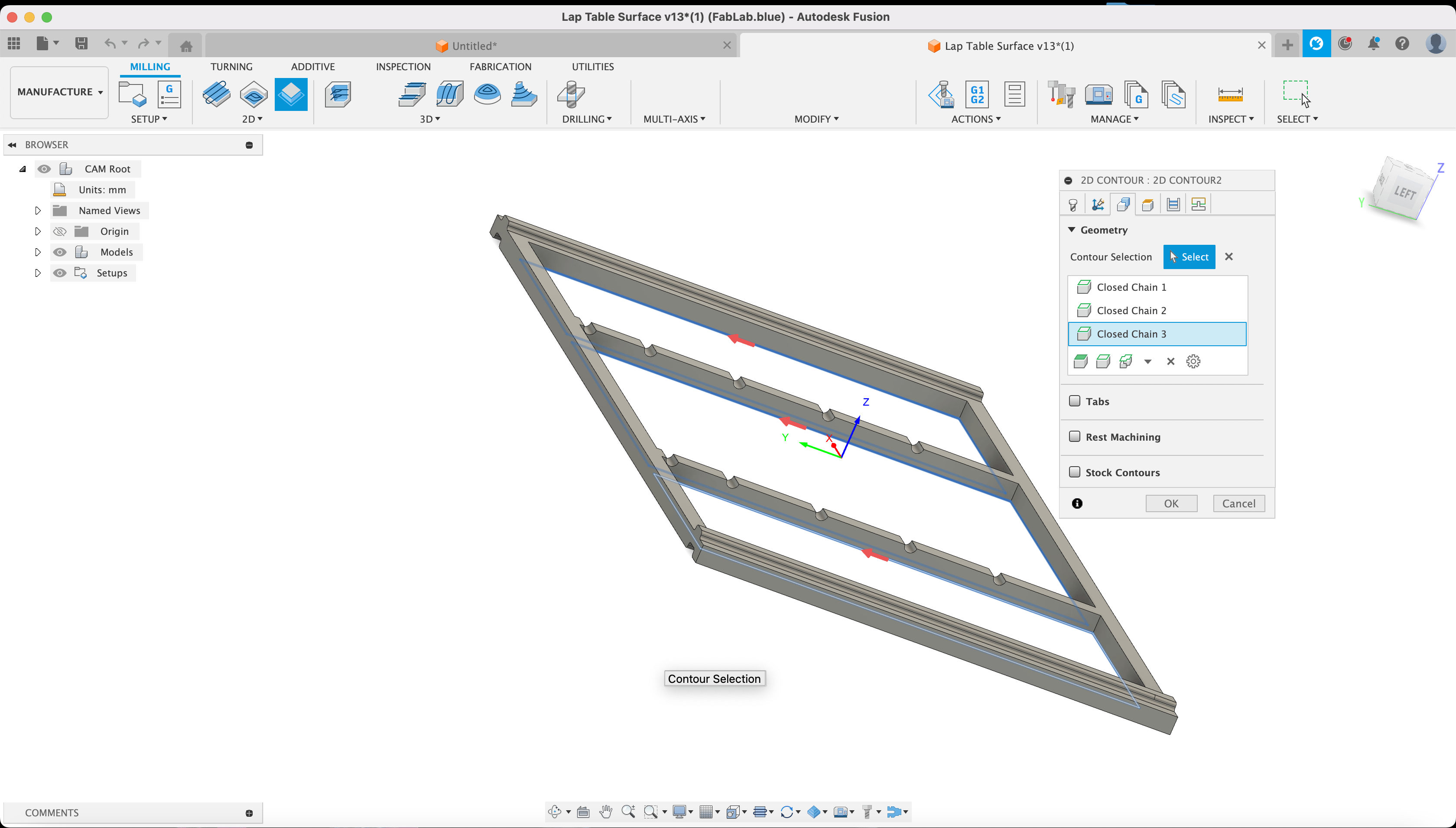
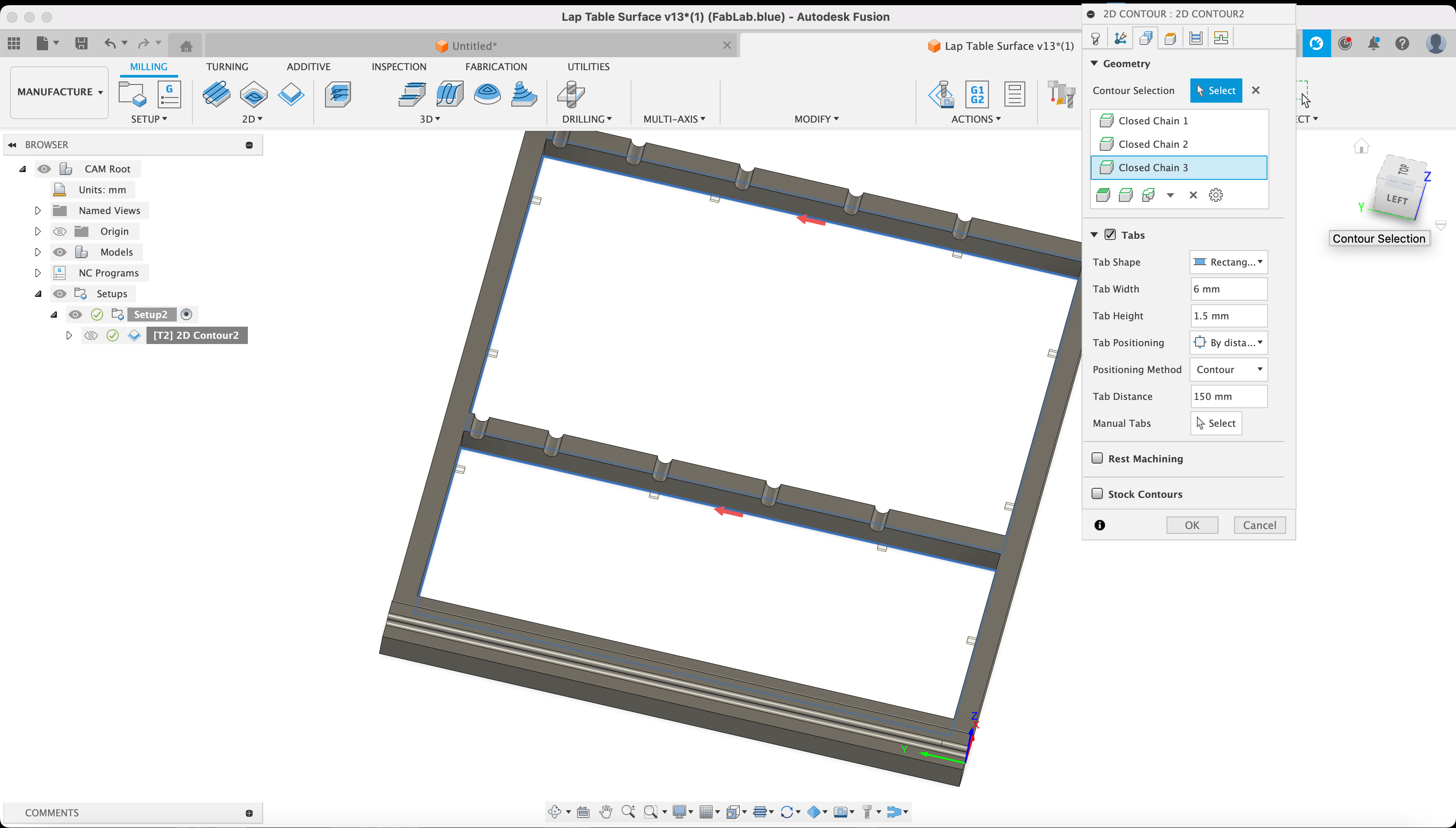
2D Contouring:
In Fusion 360’s Manufacture workspace, start with a New Setup by selecting
the origin and setting the stock point to the lower left edge of the piece, ensuring the z-axis
is pointing upwards.
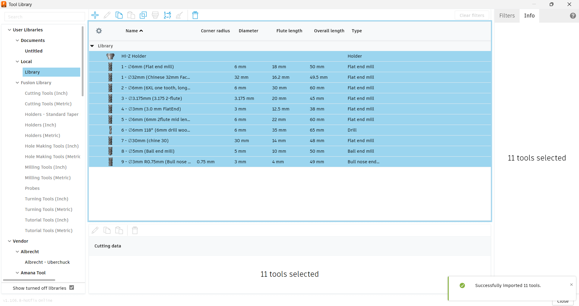
Then, navigate to the 2D menu and select 2D contouring. Choose the tool from
the preset library, specifically the 6mm flat (6XL one Tooth, Long shaft).
This selection automatically applies the correct specifications for cutting speed and the
cutter.
Next, open the Geometry tab, select the bottom edges of the frame, enable
Tabs, and set the tab distance to 150mm.
Proceed to the Passes tab, check the Roughing passes box, and
set the maximum stepover to 3 mm.
Additionally, enable Multiple Depths and set the maximum roughness to 2mm.
Lastly, ensure Smoothing is checked.
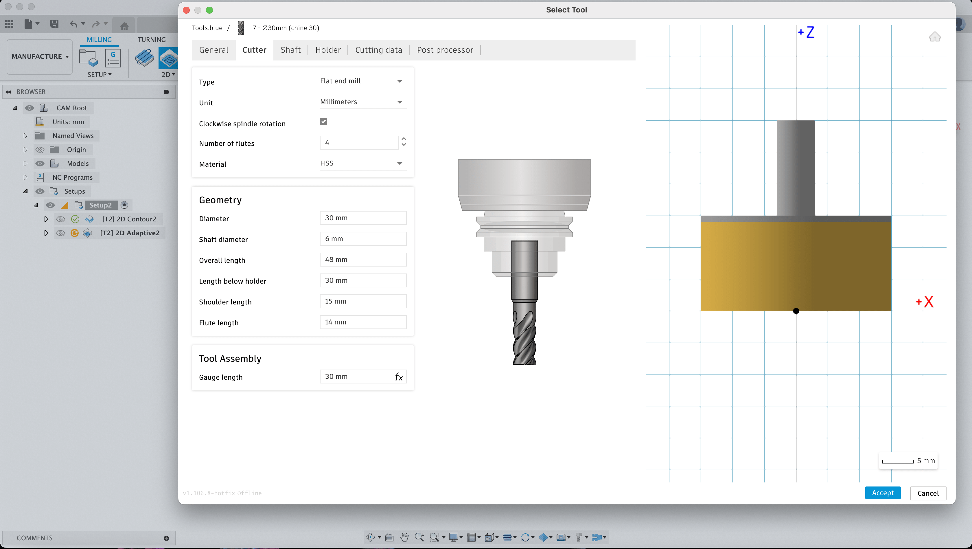
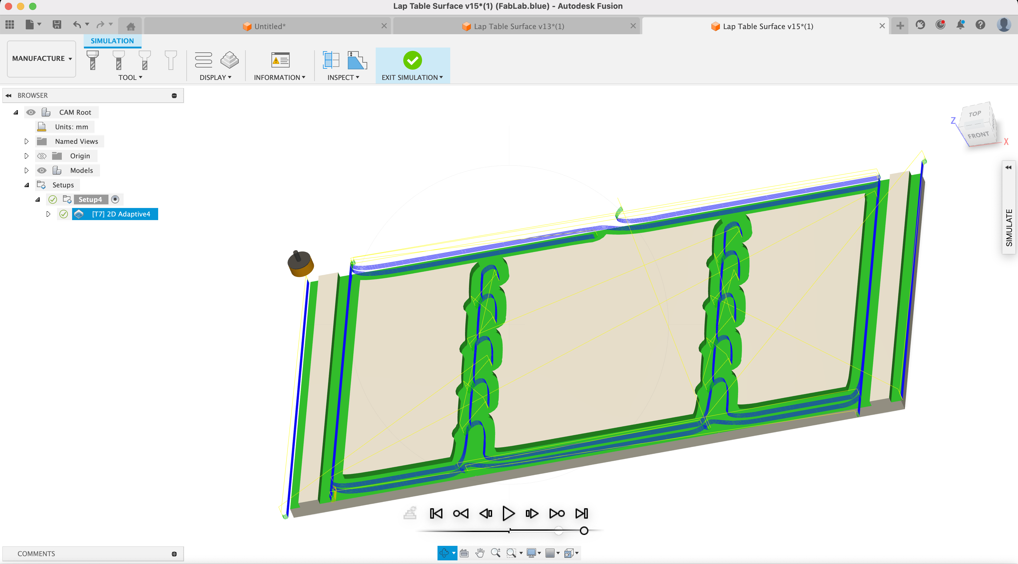
Adaptive Clearing:
To surface or "shave" the 24mm thick plywood piece to the desired
thickness, use a flat end mill.
This requires adding a new tool (30 mm surfacing bit) to the tool library and configuring the
cutting parameters to match the machine's specifications.
Afterwards, select Adaptive Clearing from the milling menu.
Adjust the settings in the Geometry tab as needed, then proceed to the
Passes tab.
Note that larger milling bits exert higher torque on the spindle; therefore, a slower feed speed
is recommended to prevent sudden plunges into the stock.
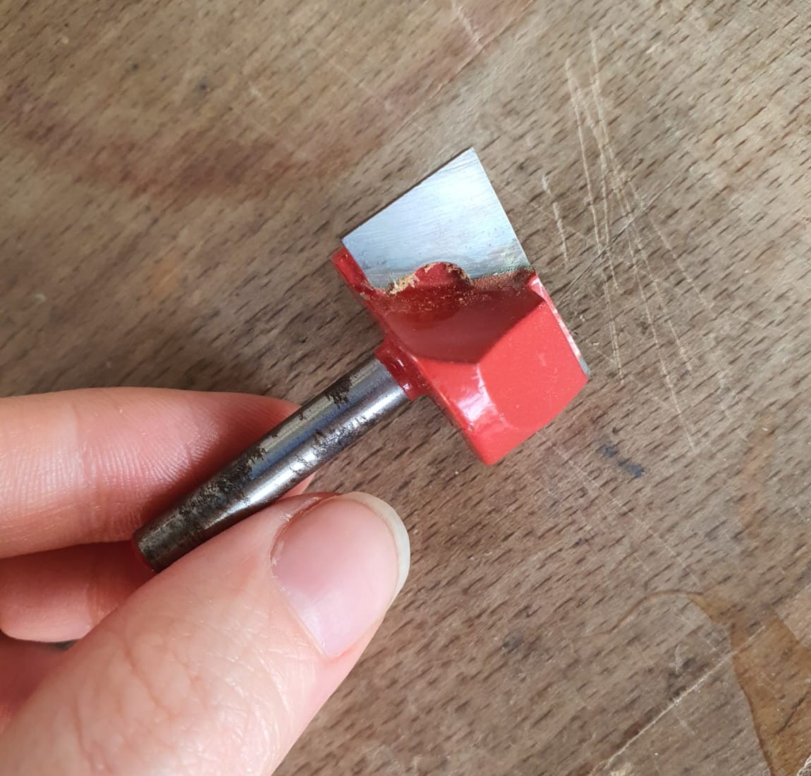
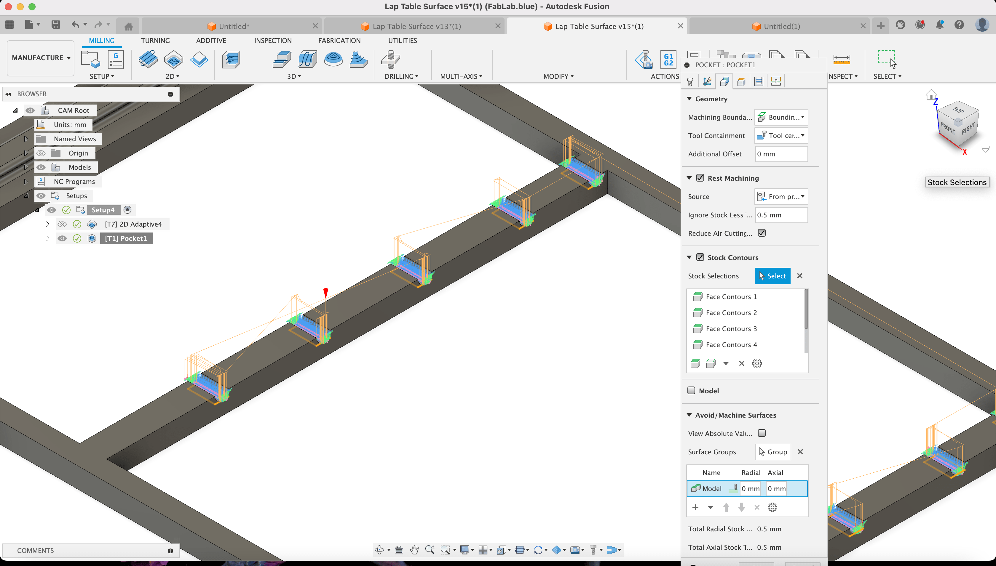
3D Pockets Clearing Pockets:
For the slots on the rail where the rod is inserted, navigate to the 3D menu
and select Pockets Clearing.
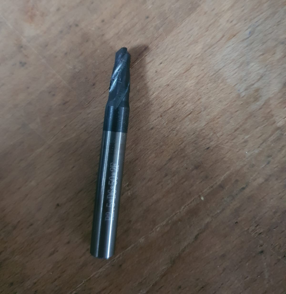
This requires adding another new tool (3 mm rounded bit) to the tool library and configuring the
cutting parameters accordingly.
The tool used here to achieve a smooth curve is a 3mm Ball end mill.
In the Geometry tab, enable Stock Contouring and select the
slot faces.
Finally, in the Passes tab, ensure Smoothing is checked.
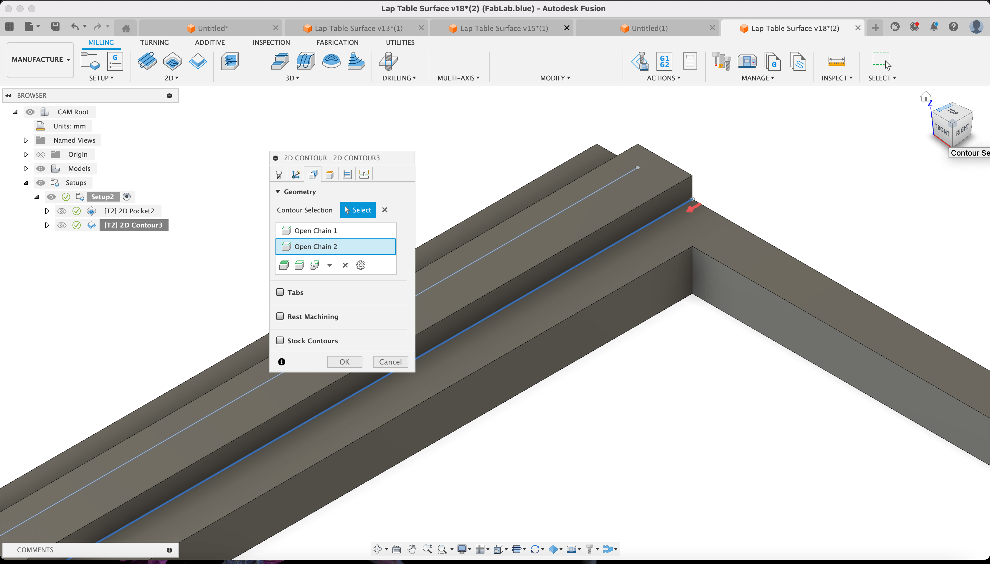
2D Contouring Joints:
Repeat the initial contouring process for the fitting "sliding" rails on the
left and right sections of the table surface, using the same tool.
Legs Joints Pockets:
For this operation, it's crucial to mill the opposite side of the stock
accurately.
To achieve this, drill holes at each corner and insert wooden dowels as alignment indicators.
In Fusion 360's Manufacture workspace, create a new setup, select the origin axis position, and
under Orientation, choose Z-axis plane/& X-axis.
Check both the Flip z-axis and x-axis boxes.
Stock box point:
Set the stock point to the lower left edge.
Next, select 2D Adaptive and choose the previously used 6mm flat end mill as
the tool.
In the Geometry tab, select the pocket (rectangle) faces.
In the Passes tab, enable Multiple Depths.
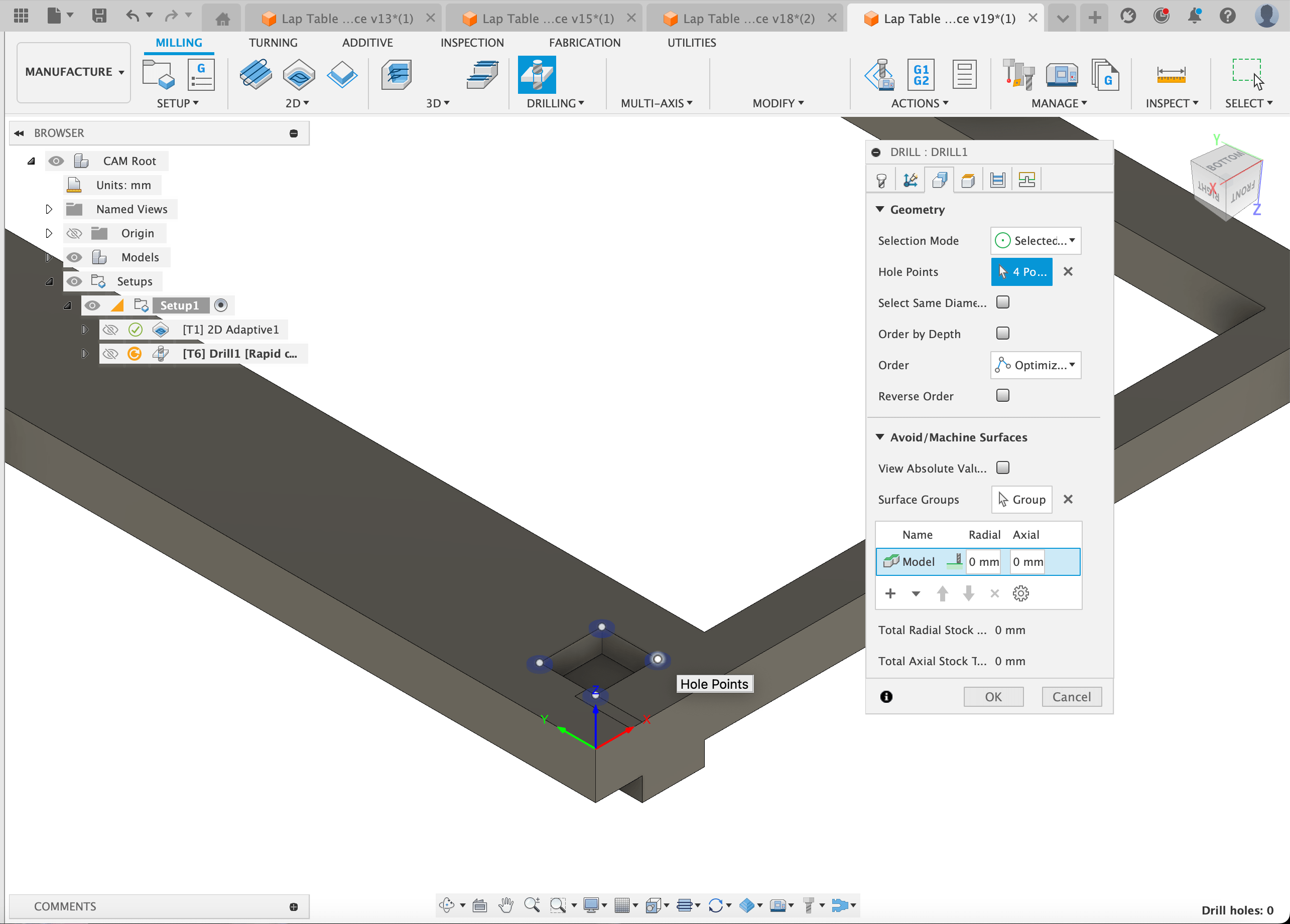
To accommodate the rounded edges produced by the milling cutter, add a Drilling
operation.
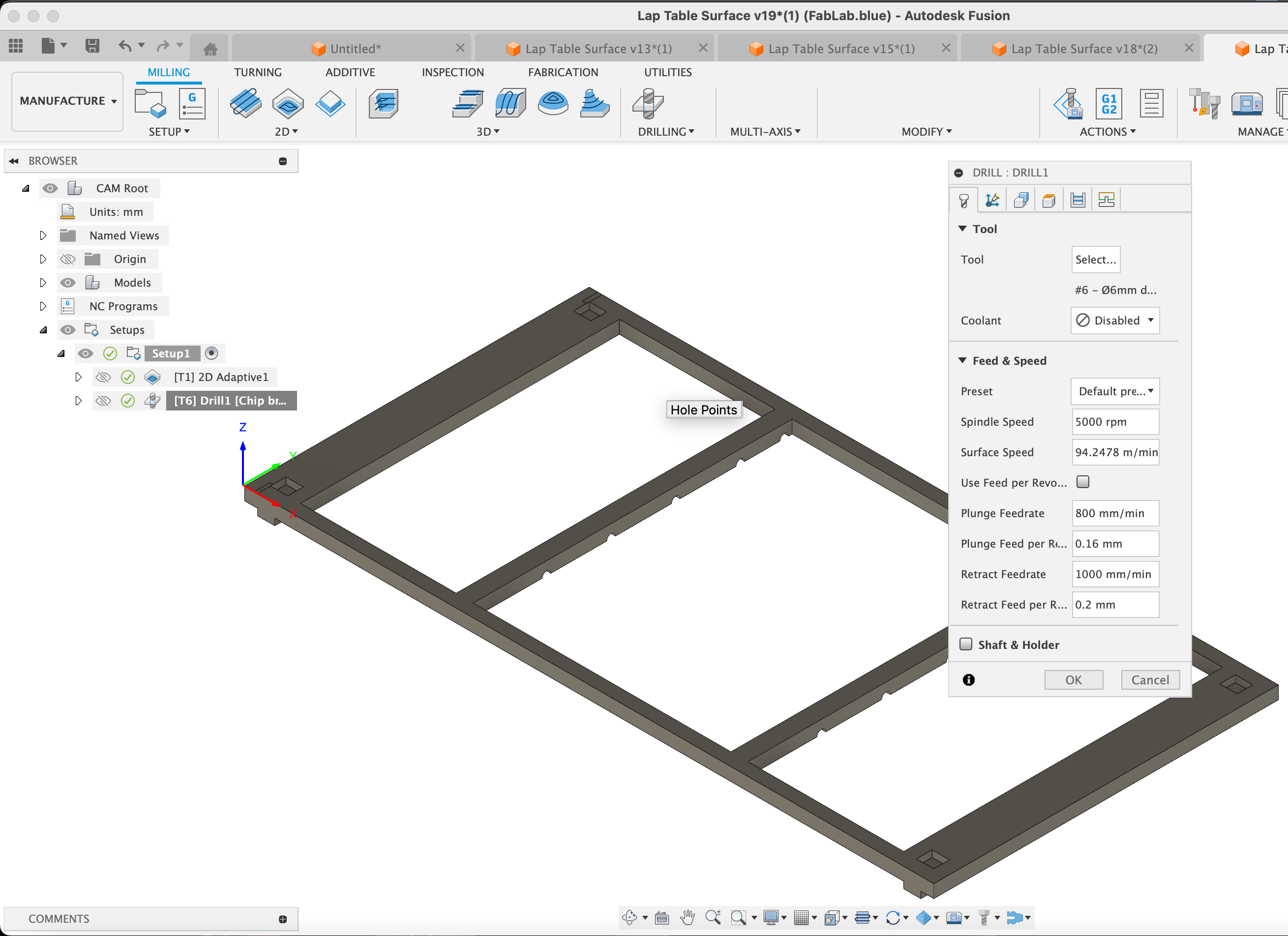
Drilling:
For the drilling tool, use the same one as before.
Under the Cycle section, select Chip break-partial retract.
In the Heights section, set the top height to Stock Top and
the bottom height to Stock Bottom, offset by 12 mm.
In the Geometry tab, designate the four corners of the pockets as the
Hole Points.
CNC Cutting and Milling
After verifying the design, I exported each generated G-Code for each piece to be cut for CNC
milling.
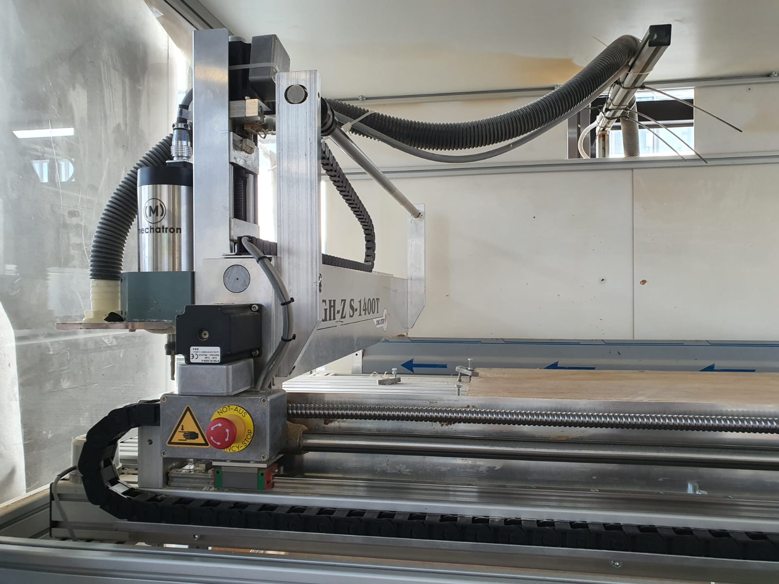
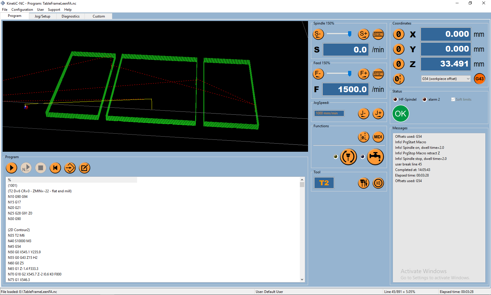
Operating CNC:
We used the
High Z 1400 NC
machine in the Blue Fablab - Kleve Campus of HSRW.
For communicating with the machine, we used
KinetiC - NC
to set up the CNC machine (locating zero position and milling in the air to make sure everything
is okay).
Open the post-processed file (.NC) in the software, and the G-code will be displayed.
Now, start by finding the zero position for the spindle in the Setup/Jog menu.
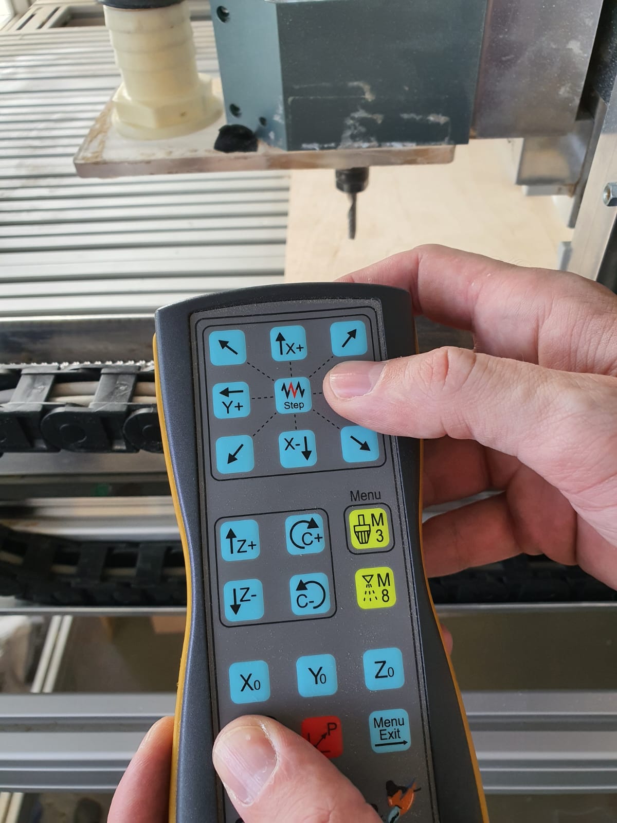
Using the remote control, you can move the spindle to position zero where the milling tool will
start cutting.
This can also be done within the software, so it's a matter of preference.
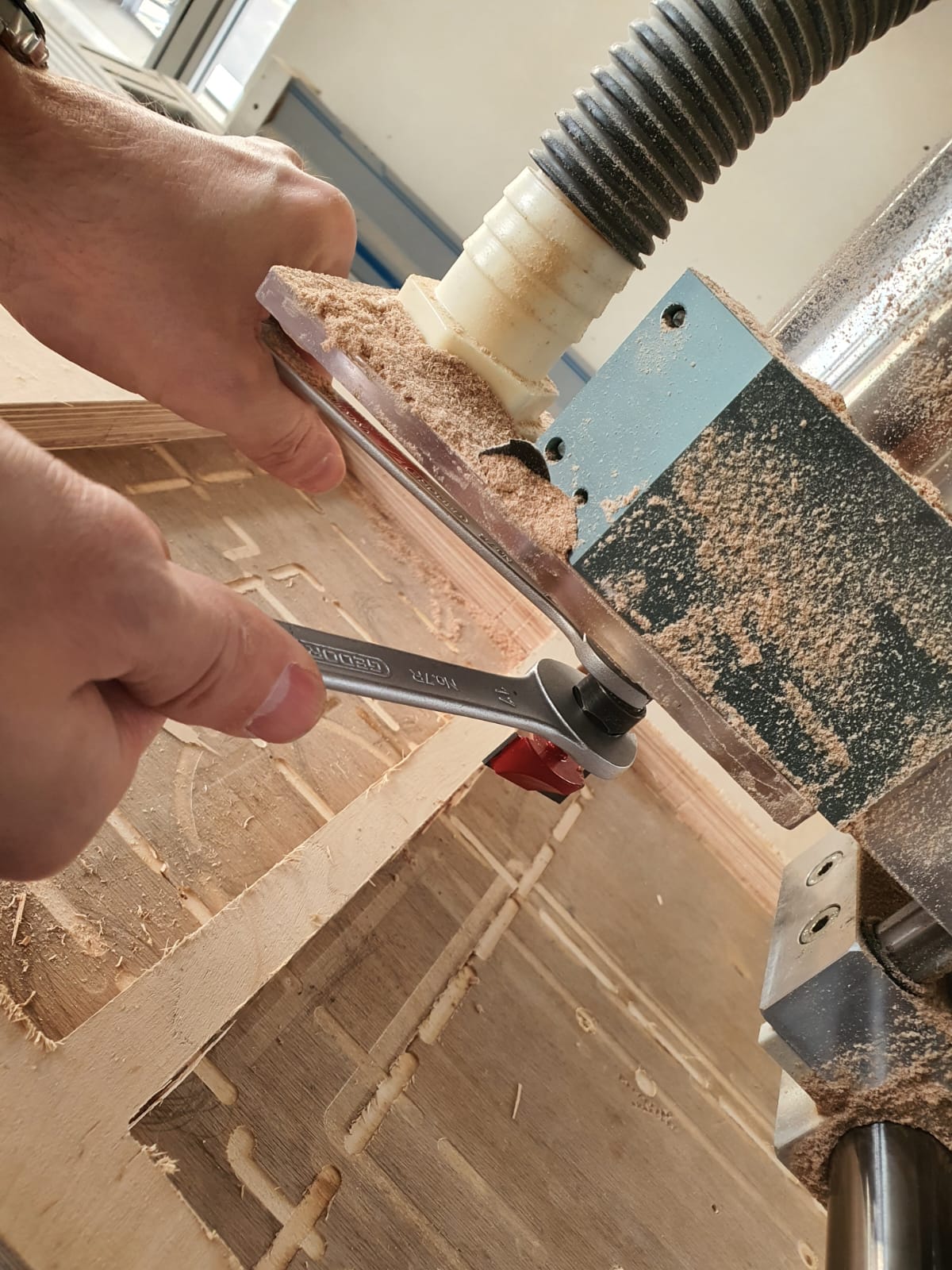
I also learned how to change the tool's shaft into the machine's head.
This process requires a lot of patience and caution when loosening and tightening the tool.
Now, to run the CNC machine:
- Upload the G-code file.
- Go to Program.
- Verify that everything is set up correctly.
- Press Play to start the job.
Be prepared to react if something goes wrong by pressing the red emergency stop
button on the machine or hitting Pause in the software.
You can also adjust the spindle speed and feed rates as needed.
When milling on the bottom side of your surface, you MUST make
sure that you place your stock as precise as possible to the exact same position. This ensures
that the machine will not mess up the zero point, nor mill or cut in shifted axis/measurements,
which in turn will impact negatively on your desired cut
In order to guarantee this, we drilled 12 holes in each corner of the cutouts, then placed a
wooden dowel in each one. Afterwards, we flipped the stock and inserted it exactly how it was
with the use of dowels as indicators.
Wooden one are the safest to use because the machine would merely cut them through if something
goes wrong.
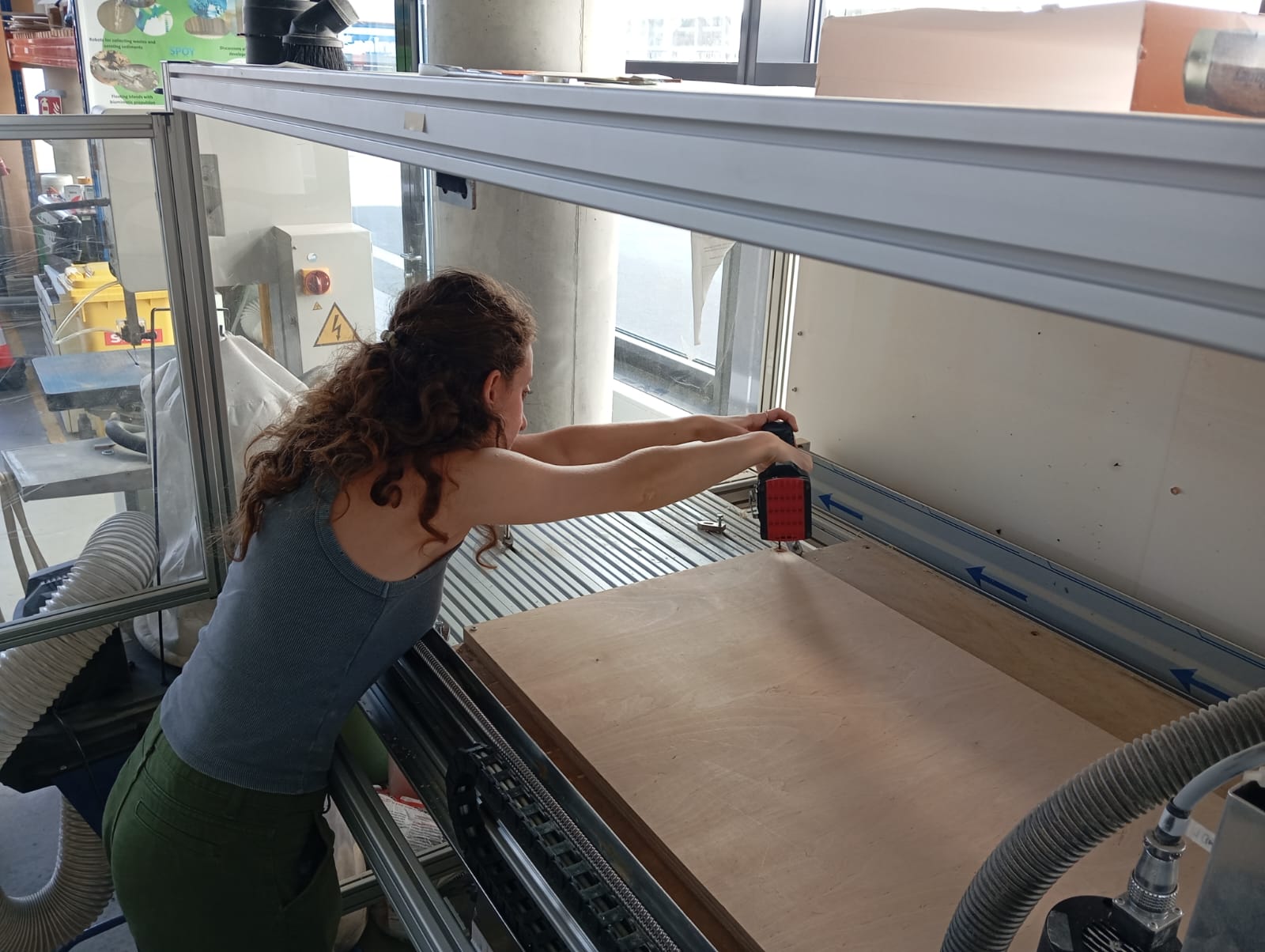
Final Checks:
- DON'T FORGET! It is important to stabilize the stock before starting to ensure all the coordinates match the real-world positioning.
- Here is me drilling screws to hold the stock in place:
CNC in Action!
The following videos show the machine operating:
- First video: Shaving the stock to the required thickness using a flat-end tool.
- Second video: Carving the slots with a rounded-end tool.
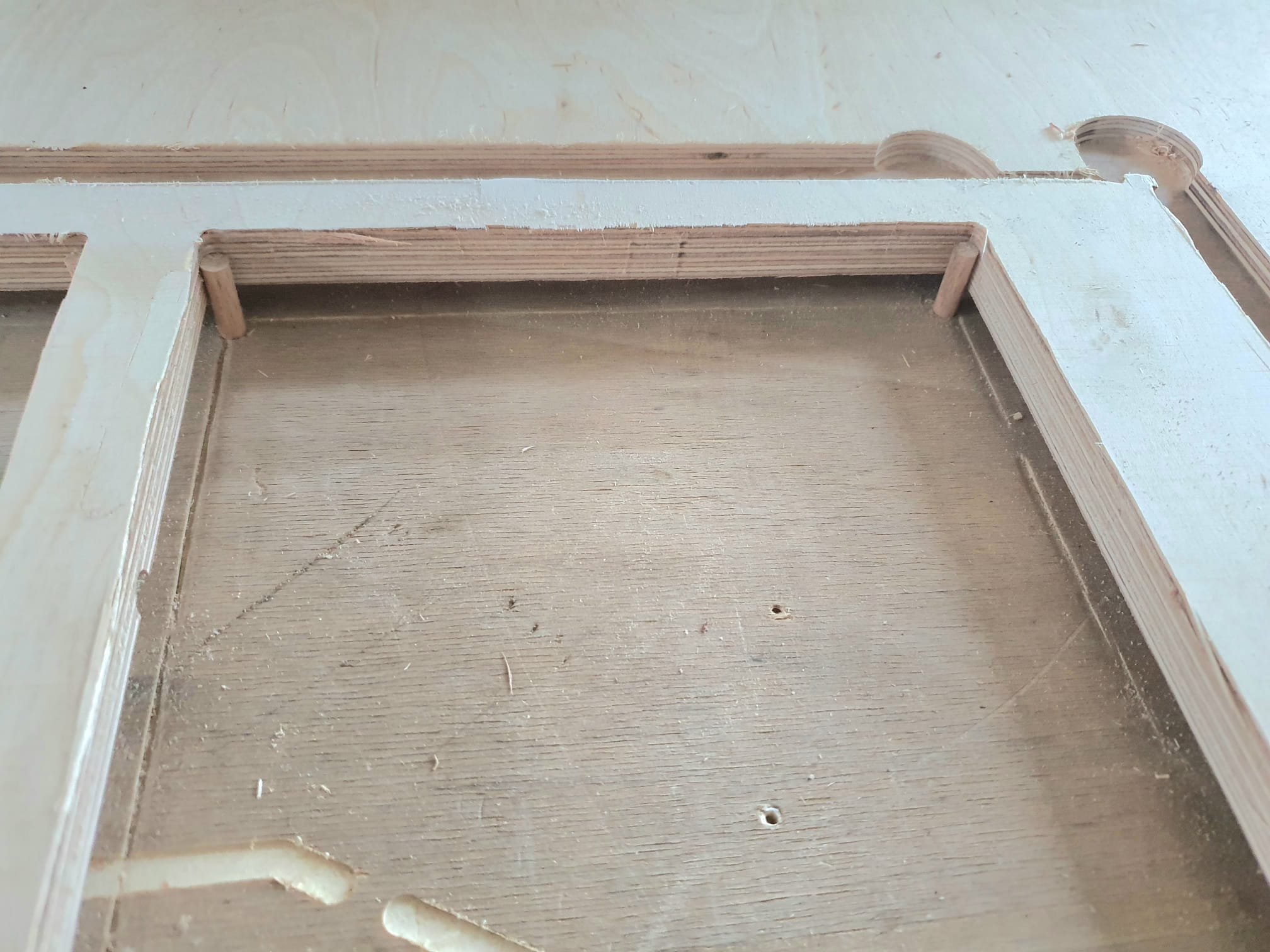
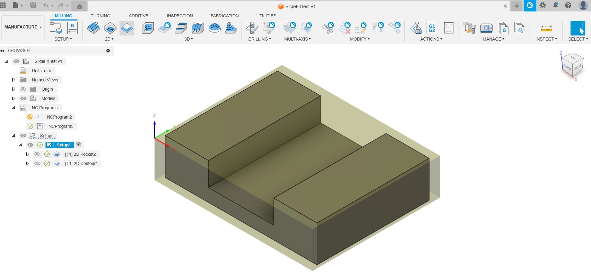
Testing the Base Rail Dimensions
The joints that will connect the left and right surface sections of the table were measured
using the caliper to figure out whether there is any slight deviation. With the caliper, the
width of the joint measured 21.5 cm instead of 20 mm.
Hence, a test piece was created to figure out how the mating part (pocket) from the other side
should be modified. This piece was exactly 21.5 mm in width (with tolerance ~0.01 mm set in the
manufacture workspace).
The test piece was fitting the the joint well, though there was slight deviation from one side
to the other when attempting to sliding it. This is potentially due to shifted zero position in
this CNC machine.
However, it should not be a big issue for this prototype, and once assembled, modification that
have to be made on the design can be clearly detected and adjusted accordingly.
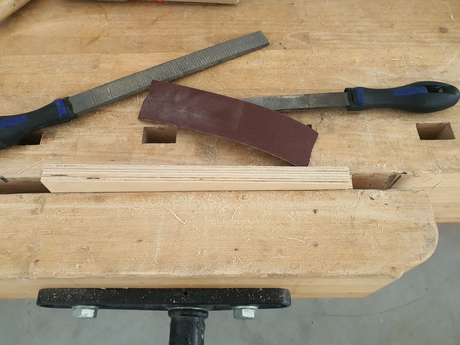
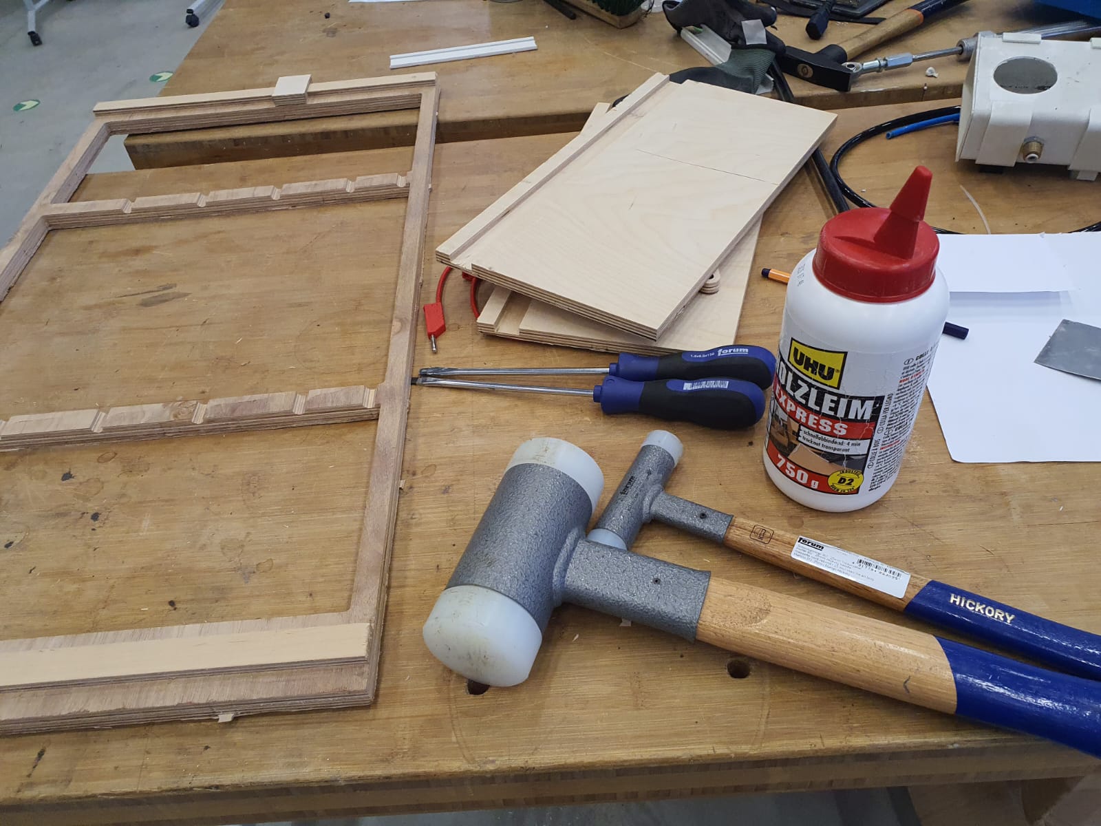
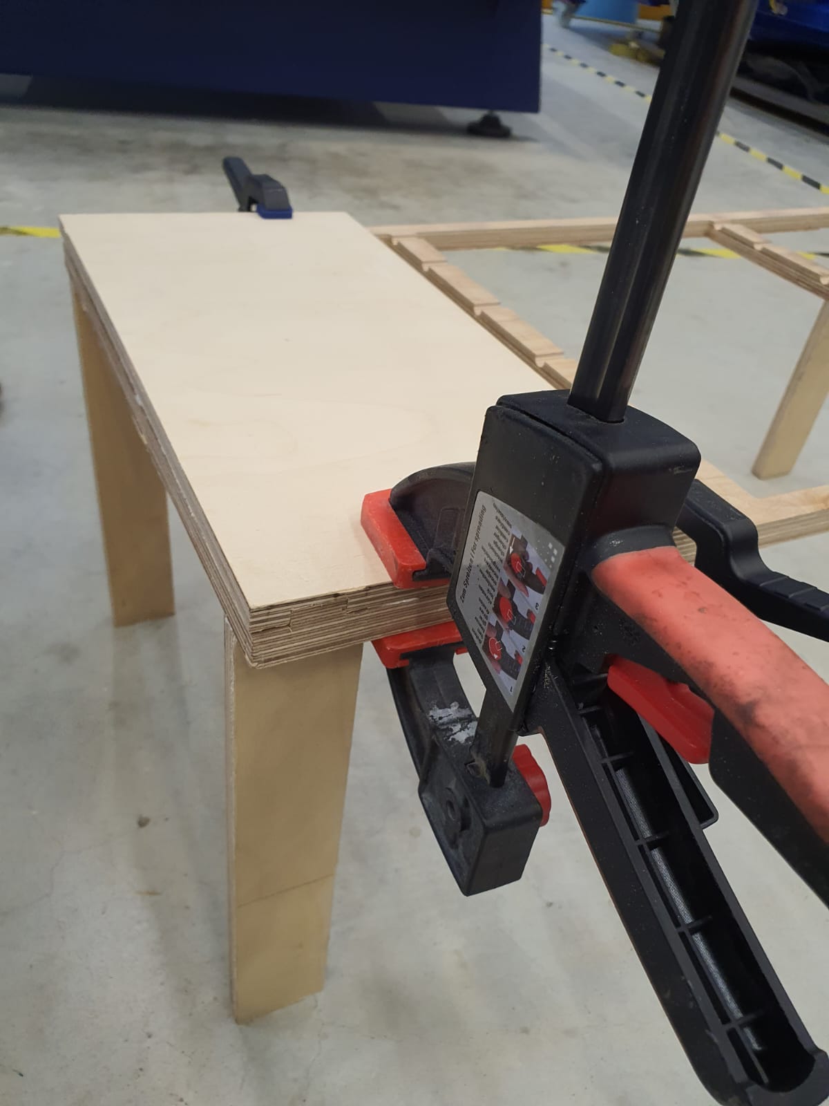
Final Assembly
-
Your friends to polish your art pieces wwhen working with wood are:
- File to remove all extra onion-like skin from the drilling
- Sanding paper for a smoother finish
- Wood Glue to repair a damaged surface
- Hammer to tight-fit pieces together
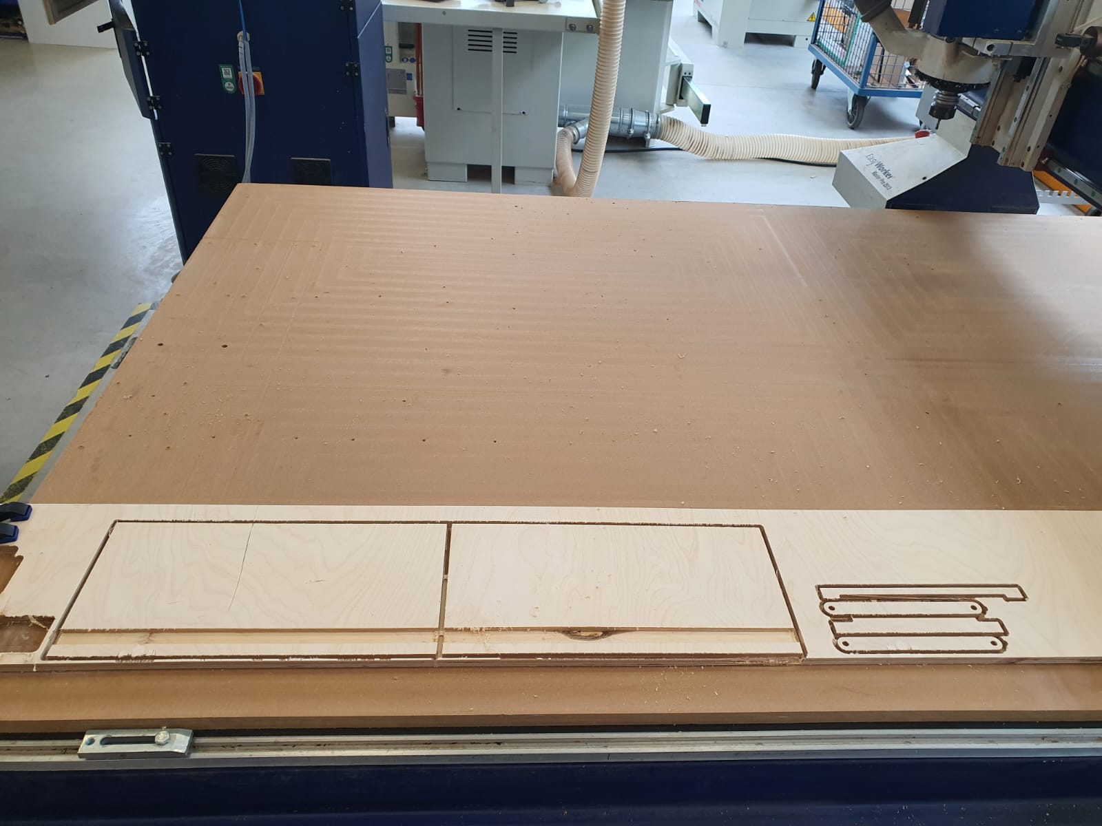
As seen in the picture, the pieces laid on our eLsign - EasyWorker
MasterPro 2513, and roughly summing up to ~1075 mm!
et voila!my 1.0 laptable version is assembled!
Final Comments on Table 1.0 version!
I’m satisfied with the adjustable‐angle mechanism in the midsection. However, one major lesson I
learned is never to cut pieces from the same assembly on two different CNC machines: they’ll
have different tolerances and deviations, which makes fitting everything together much harder.
As a result, I ended up using chisels and files to get all the pieces to fit properly.
Although I originally designed everything to require no screws or glue, the dimensional
variations—and the need for stability, especially in the legs—forced me to use a little glue and
a few screws.
For my final table, I definitely want to redesign the legs so they fold; that way I can store
the table with maximum space efficiency. I also plan to allow more time for multiple iterations
and to incorporate my instructor’s feedback several times before cutting the final design.
Conclusion and Reflection
With
adjustable artist boards for the angle concept and
digitally remastered joinery I received some inspiration on tight-fitting, no screws
connections. Additionally, I learned how to operate the CNC machine first hand and do the
process of setting the zero point. uploadng the G-Code into KinetiC
-NC
to send the cutting command to the machine. Nevertheless, there were alot of moments of
failures
and random mistakes. We had to reset the zero point few times, the machine suddenly plunged
into
the bed and we feared unwanted cut. Therefore, it is important to be very reactive when the
machines starts to home and then cut for you to be able to stop the machine instantly if
something unforeseen happens!
However, after few more testing and understanding errros attempts, we figured out that
homing is
required inbetween each jog/setup so that the machine does read the G-code correctly and
perform
the desired function. Moreover, we had the limitation for the access to our fablab in
Kamp-Lintfort, which pushed us to go for our second blue fablab of HSRW-Kleve and the
machine
there was very unpredictable and slow. So we ended up cutting only one piece out of the
whole
table assembly design. Hence, the assginment will be finlaized once all pieces are cut and
assembled and a picture of that will be added!
All in all, I learned tha CNCing, or Computer Numerical Control, can be very slow and
unpredictable process, and that is a skill that can not be developed over only two days of
work.
Hence, only more practice and more making mistakes and learning is needed!
YouTube Tutorials:
- Testing NEW CNC Joint - Bed-Table Build
- DoveTail Half-Lap Joint
- Basic Wood Joinery- Eric Brennan
Files
- LapTable 3D Design
- LapTablePrototype.f3d
- LapTable 3D Design 2.0
- LapTableUpdate.f3d
- Slide Joint Fit Test
- SlideFitTest.f3d
- Pieces Laid out in Manufacture Workspace (~1m)
- Assemblypieces(~1m).f3d