Week 10: Output Devices
Group Assignment
We measured and analyzed the behavior of various output devices (LEDs, buzzers, motors) using an oscilloscope. 🔗 Group assignment link
Overview
Output devices respond to control signals by producing physical actions like movement or light. For this week, I used an SG90 servo motor controlled by the board I made in Week 8.
What is a Servo Motor?
The SG90 micro servo motor rotates from 0° to 180° and uses PWM signals for control. It’s commonly used in robotics for precise angle positioning.
.jpg)
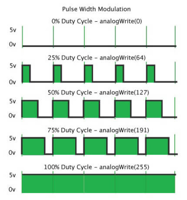
PWM (Pulse Width Modulation)
PWM sends rapid ON/OFF pulses to simulate analog control. The servo uses this to interpret position:

1 mspulse → ~0°1.5 mspulse → ~90°2 mspulse → ~180°
Wiring
| Servo Wire Color | Function | Connected To |
|---|---|---|
| Brown | GND | GND |
| Red | VCC | 3.3V |
| Orange | Signal | GPIO 6 |
Power Consumption
I used a multimeter to measure the current draw of the SG90:
- Idle (holding position): ~7 mA
- Under load (moving): ~110–130 mA
This is important for choosing appropriate power supplies in final projects.
Code and Programming
I used the ESP32Servo library since I'm working with an ESP32-C3 board. The servo is swept back and forth smoothly with 15ms intervals:
#include <ESP32Servo.h>

Servo myservo;
int pos = 0;

void setup() {
  myservo.setPeriodHertz(50);
  myservo.attach(6, 500, 2500);
}

void loop() {
  for (pos = 0; pos <= 180; pos += 1) {
    myservo.write(pos);
    delay(15);
  }
  for (pos = 180; pos >= 0; pos -= 1) {
    myservo.write(pos);
    delay(15);
  }
}
Problems and Troubleshooting
While setting up the servo with my ESP32-C3 board, I ran into several issues:
- Missing Library: Initially, I forgot to include the correct header:
#include <ESP32Servo.h>. This caused a compilation error because the IDE didn’t know which library to use. - Library Not Installed: After fixing the syntax, I still got an error: “ESP32Servo.h: No such file or directory.” I realized I hadn’t installed the
ESP32Servolibrary, so I used the Arduino Library Manager to install it. - Trying `writeMicroseconds()`: I also tested an alternate method using
writeMicroseconds()instead ofwrite(), but later reverted towrite()as it gave smoother and more reliable results with my SG90 servo.
After resolving these issues, the servo worked properly with my custom PCB and GPIO 6 using the ESP32Servo library.
Hero Shot
I used the custom PCB I designed and produced in Electronics Production week to control the servo using an Arduino-compatible microcontroller.