Week 08 - Electronics Production
Assignment
Group Assignment:
Individual Assignment:
- Make and test a microcontroller development board that you designed
Software and Machine Used
After completing the design of my PCB board in KiCad, I exported the necessary Gerber (.gbr) files for manufacturing. The production process involved two key software tools: Cube 3D Cam Pro for CAM preparation, and UCCNC for CNC machine control.
Cube 3D Cam Pro:
I imported the Gerber files into the software and assigned the correct layers for each process:
- Top Layer: used for engraving traces (
F-cu.gbr,gtl) - Mechanical Layer: used for cutting the board outline (
Edge_Cuts.gbr,gko)
Once the layers were properly configured, I generated the G-code files required for both engraving and cutting. These files were later executed using UCCNC to run the Cube 3D MxPro milling machine.
Mods allowed me to define cut depth, offset count, and simulate toolpaths. I exported G-code files to use in UCCNC for controlling the CNC.

This is the Mods interface where I prepared the traces and outline toolpaths for the PCB milling process.
Milling Process
I secured the copper-clad board using double-sided tape to prevent shifting during milling.

This is the FR1 board mounted onto the sacrificial layer of the CNC machine bed.

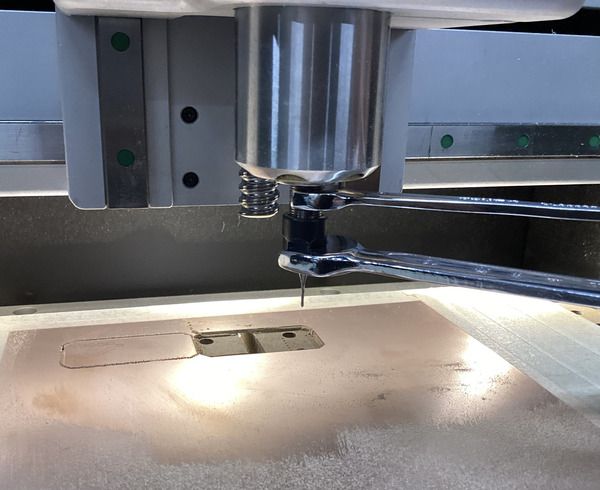
I used the probe feature to zero the Z-axis accurately for proper trace depth milling.

Here’s the UCCNC software interface where I loaded and executed the engraving and outline G-code files.

This image shows the process of changing the bit between engraving and outline cutting operations.

This is the final output after milling — the traces and outline are completed and cleanly separated.
Used Tool Bits
Two different end mills were used in this process: one for fine detail and the other for cutting out the board.
The green one is a 0.4 mm end mill used for traces, and the black one is a 1.0 mm end mill used for the outline.
Issues and Fixes
Initially, the traces were not milled deep enough due to incorrect Z-axis calibration.

This was the failed board. The traces are faint and not properly isolated. I fixed this by lowering the Z offset slightly.
Soldering Process

Here is my soldering station setup, including a temperature-controlled soldering iron, magnifier lamp, and anti-static surface.

I used a fume extractor to safely ventilate soldering smoke. This is especially important when using lead-based solder.
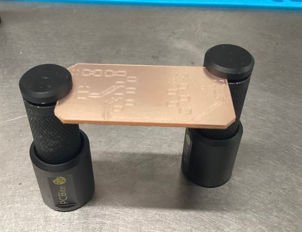
The PCB was held in place using PCBite magnetic holders, which helped me solder components steadily and accurately.

This brass sponge cleaner was used to clean the soldering iron tip between joints, preventing oxidation and improving solder flow.

This is the solder I used: 0.75 mm Sn60/Pb40 with 2% flux. I chose this because it has a low melting point and offers smooth soldering for fine-pitch SMD work.

Final soldered board with all components — headers, resistors, capacitors, and the microcontroller — properly attached and cleaned.
Testing the Board with an Onboard LED
To confirm that the output pin connections on my custom PCB were correctly functioning, I tested the onboard LED circuit connected to GPIO2 (pin D2 on the XIAO ESP32-C3). This pin is safe for general-purpose output and not involved in the ESP32-C3's boot process.
I uploaded a simple blink sketch that toggles the LED every 500 milliseconds. This allowed me to verify both the soldered connection to the LED and the output drive capabilities of the microcontroller.
#define LED_PIN 2  // D2 is GPIO2 on XIAO ESP32-C3

      void setup() {
        pinMode(LED_PIN, OUTPUT);  // Set pin as output
      }

      void loop() {
        digitalWrite(LED_PIN, HIGH);  // Turn LED on
        delay(500);
        digitalWrite(LED_PIN, LOW);   // Turn LED off
        delay(500);
      }
Once the board was powered via USB, the LED blinked steadily, confirming that the circuit was complete and functional. This test provided visual confirmation that GPIO2 was working as expected, and that both the resistor and LED were correctly positioned in the circuit.
Hero Shot

This is the final, working board with the Seeed Studio XIAO ESP32-C3 mounted and programmed successfully.
Conclusion
During this assignment, I went through the full process of manufacturing a custom microcontroller development board—from designing in KiCad to milling with Cube 3D MxPro and finally soldering and testing the board. I learned how to correctly generate and prepare G-code files, operate CNC software (Cube 3D Cam Pro and UCCNC), calibrate tool offsets, and troubleshoot production errors like incorrect trace depth.
The hands-on soldering experience helped me improve my SMD soldering skills, and I also understood the importance of good workplace setup, including proper ventilation and steady board holders. Finally, I validated my design by uploading a servo control program, which confirmed that the board works as intended. Overall, this week gave me a complete understanding of the electronics production pipeline—from digital design to physical realization.