Hugo the Drawing Arm
Summary
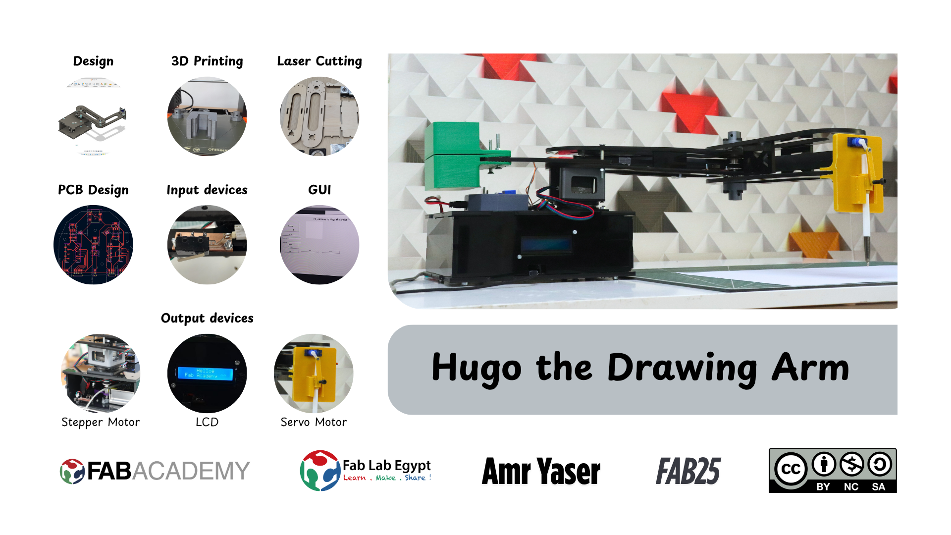
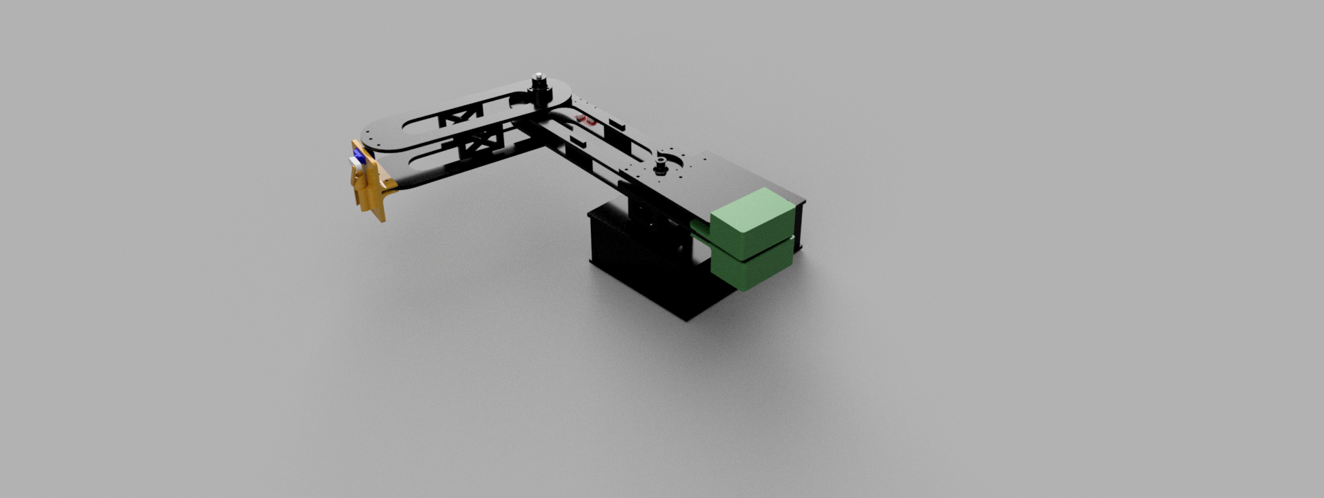
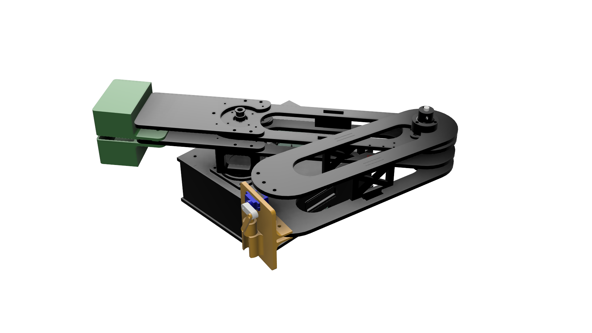
Hugo is a 2D drawing robot arm based on Scara configuration. Hugo is connected to a GUI running on a PC that sends to it X ans Y coordinated to make it move. Also it has a pen holder mechanism moving by a servo motor to raise the pen up and down.
Features
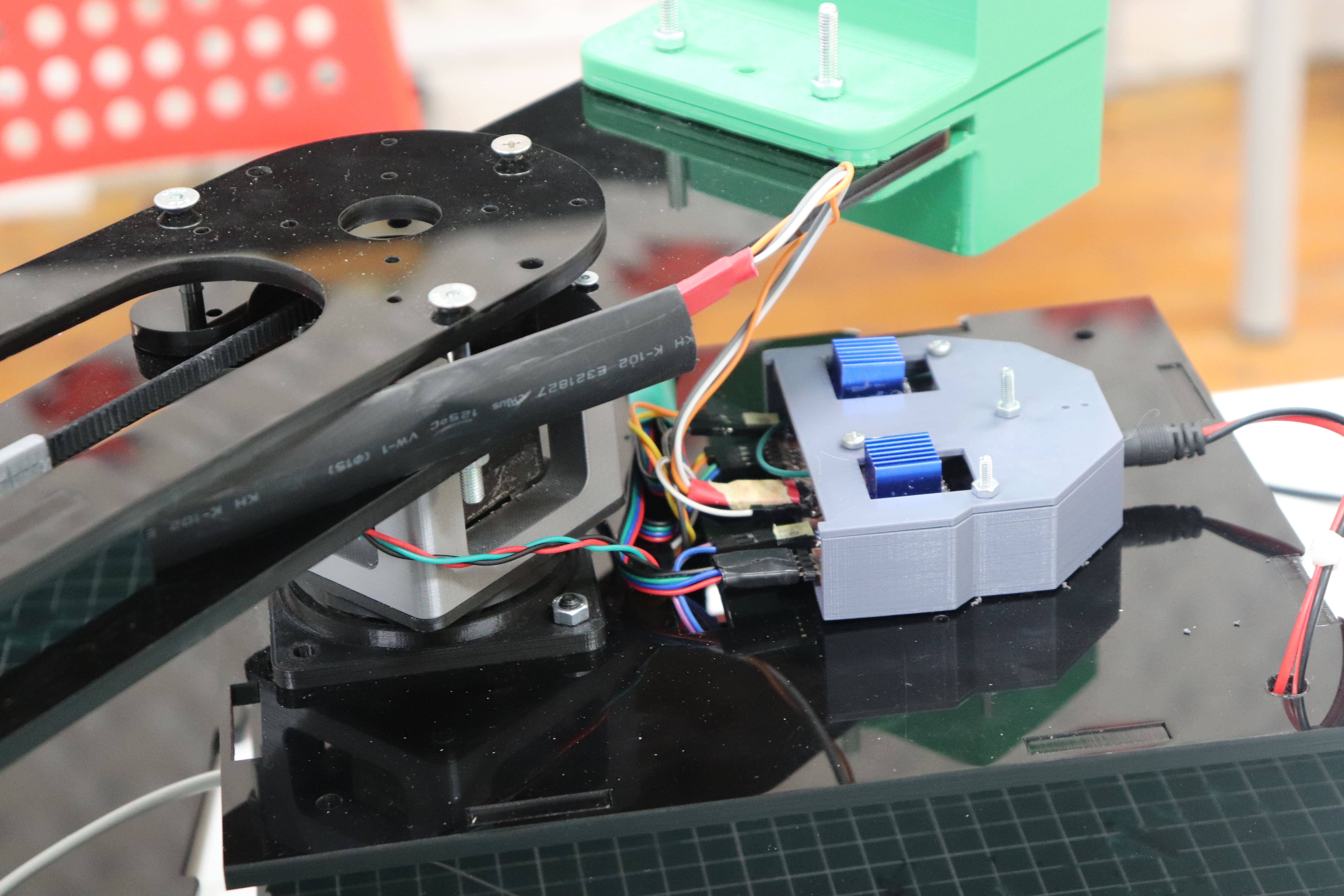
- Actuation is by two stepper motors with GT2 belt and pulley system
- Pen-lifting mechanism using a servo motor
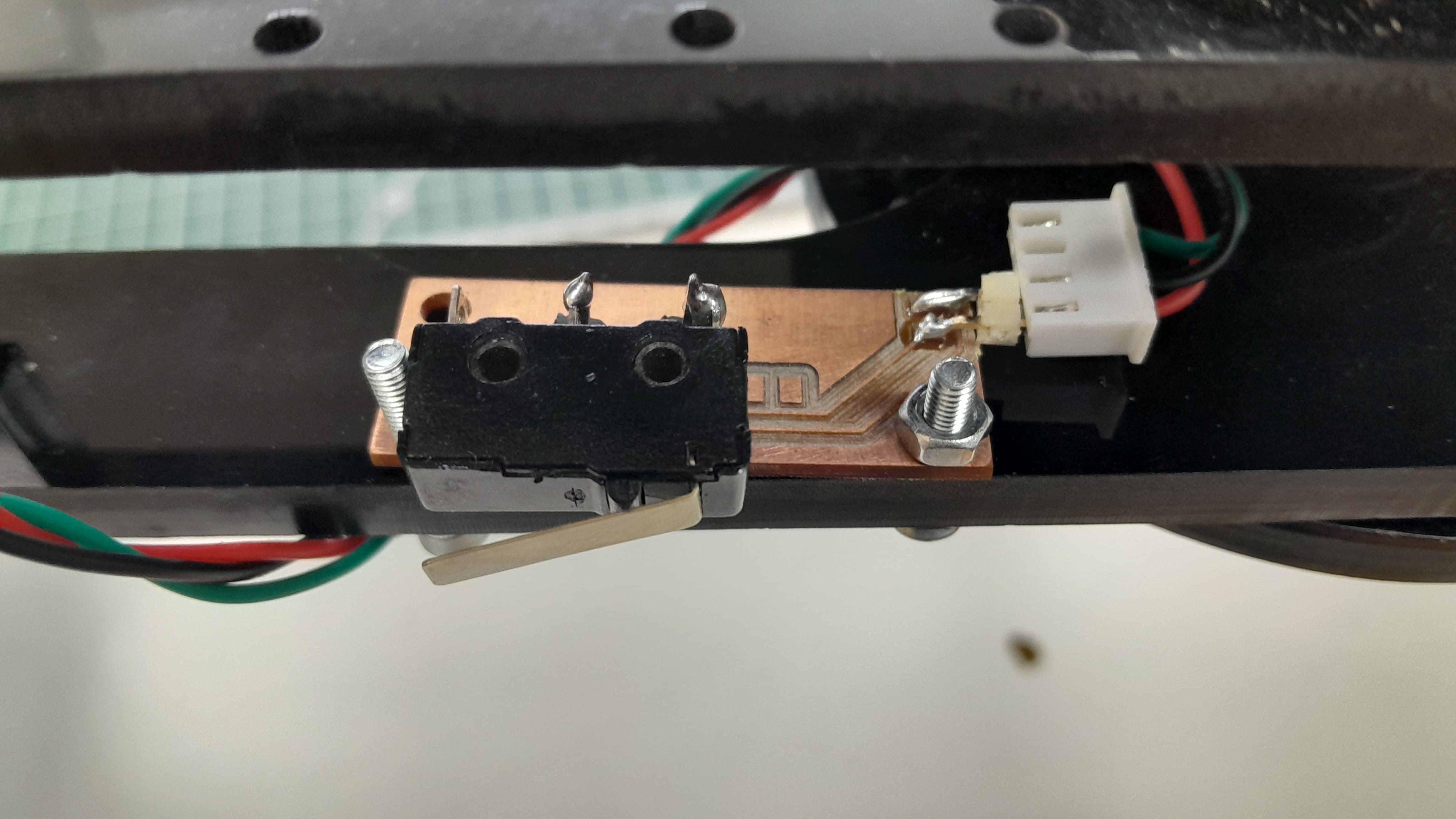
- Limit switch homing (PCB made.)
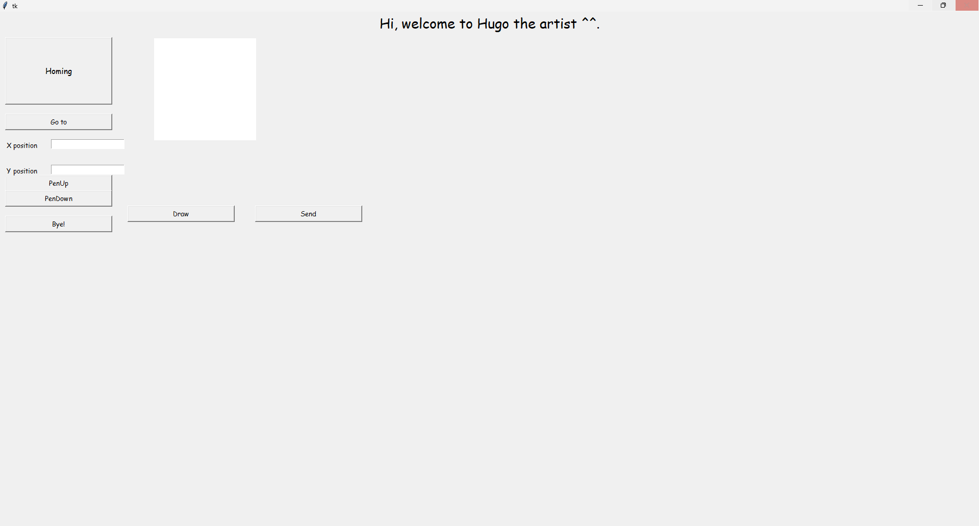
- Serial-controlled drawing from a computer using a GUI made using tkinter
- Live LCD feedback to debug what happens and show the current angles each joint takes.
Here is the final result that I have reached ^^.
Development Process
In the development process I will include Talk about the designing process for the mechanical frame, fabrication processes, designing PCB, talk about the components I used and programming. Also I will include the failures and difficulties I have faced and my future plans for such project.
CAD design process:
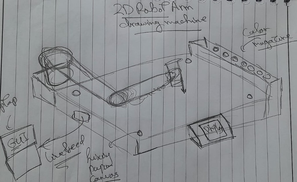
Sketching:
I started with sketching on paper to draw all what I want to do in my project as you can see I added the GUI and a display and colour magazine (If only you could know the future ^^).
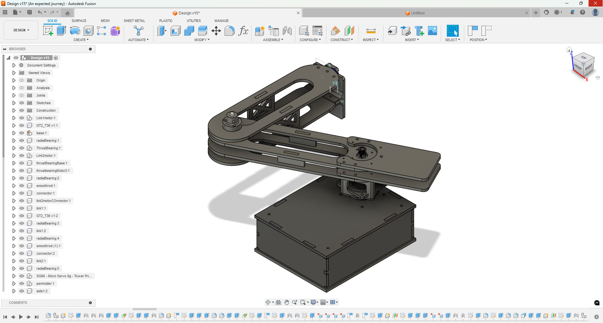
CAD design:
I used Autodesk Fusion 360 to design the 3D printed parts and the laser cut parts.
.png)
Adding Acrylic appearance:
.png)
.png)
Rendering:
Animation:
Fabrication of the prototype:
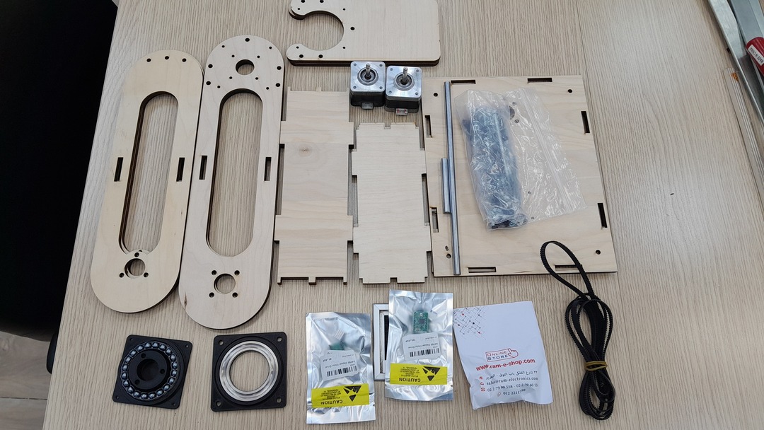
Here I will show you the fabrication of the laser cut parts and 3D printed parts and assemble:
Laser cut:
Wooden prototype:
Acrylic final version:
3D printing:
Parts:
Assemble the prototype:
.jpg)
.jpg)
.jpg)
Here I 3d printed some 3d parts to hold and belt together.
.jpg)
.jpg)
Assemble the final version:
.jpg)
.jpg)
.jpg)
Electronics Design:
I designed the main board (controller board) in Week_6. and fabrciated it in Week_8.
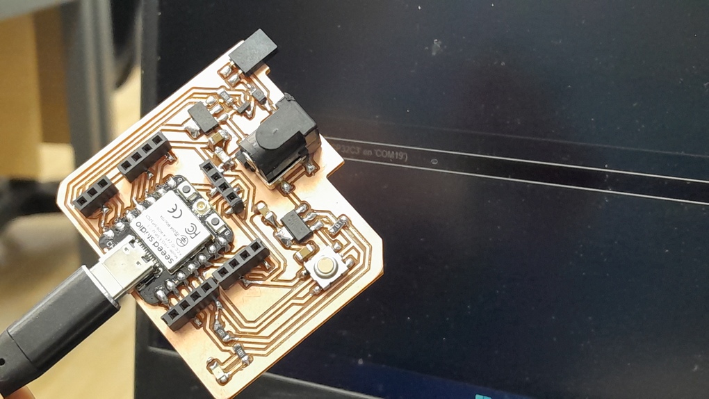
So I designed the motor board where i will connect the motors pins, the drivers and the main power. Also I design the PCB for the limit switch I bought.
Design:
.png)
I designed another motor board because the other one failed due to incorrect soldering and overheating the pads as they were removed or became weakly aatached to the board.
.png)
This the limitswitch board I used this foot print to get just the right distance between the limit switch terminals.
.png)
Fabrication:
First board:
.jpg)
.jpg)
.jpg)
The first board I made an transparent acrylic sheet as a cover to it like a sandwich.
Second board:
.jpg)
For my second board I wanted to make a 3D printed cover:
Limitswitch board:
Programming and GUI development:
GUI development:
For the GUI I used tkinter to biuld it and I learned that in week_14. I started by sketching a thought about the GUI and how it will look like. As discussed in week 14 the GUI sends X and Y coordinated to the board using pyserial.

Then started biulding it bit by bit until I reached this:
For the GUI code you can see click here.
As you can see in the GUI each button has a function to go like the homing button (it sends home to the xiao via pyserial), go to button sends X and Y coordinates, pen up and pen down buttons control the servo motor. Bye button exits the GUI. the Draw button prints the array of points drawn in the canvas and the send button sends the array to the xiao one point a time.
Xiao ESP32 C3 code:
In this code Xiao ESP32 C3 receives X and Y coordinates then it calculate the inverse kinematics and the move each motor the right number of steps to take the right angle.
I used Chatgpt for optimizing this code to get the best out of the calculation and the acceleration and deceleration. you can see here.
Here I will divide my code into sections with a description for each one:
Definitions and lybraries I used:
    #include <ESP32Servo.h>
    #include <LiquidCrystal_I2C.h>

    LiquidCrystal_I2C lcd(0x27, 16, 2);


    Servo penMotor;

    // Link lengths
    float link1Length = 270;
    float link2Length = 285;

    // Motor pins
    int link1MotorStep = D0;
    int link1MotorDirection = D1;
    int link2MotorStep = D2;
    int link2MotorDirection = D3;

    // Directions

    int awayFromlimitswitch1 = 1;
    int awayFromlimitswitch2 = 1;

    int towardslimitswitch1 = 0;
    int towardslimitswitch2 = 0;

    // Limit switches
    int limitswitch1 = D6;
    int limitswitch2 = D7;

    // Motor settings
    int stepsPerRevolution = 200;
    float microsteppingFactor = 8.0;
    float inputPulleyTeethNum = 20.0;
    float outputPulleyTeethNum = 36.0;
    int totalsteps = microsteppingFactor * stepsPerRevolution;

    int delay1 = 3000;
    int delay2 = 2000;

    // Offsets & Homing angles
    float offsetX = 0;
    float offsetY = 285;
    float link1HomingAngle = 90;   // in degrees
    float link2HomingAngle = 120;   // in degrees

    int currentangle1 = 0;
    int currentangle2 = 0;

    // int gototestangle1 = 23;
    // int gototestangle2 = 77;

    int servopin = D8;
Next some functions I used Chatgpt to make and help me optimize:
I needed a function to accelerate and decelerate the motors for me using delay I didn't reach a solution where i can vary the delay with the steps to accelerate for a time and decelerate before reaching the final stage so I used Chatgpt to make it. I did make a function that is floatMap() where it maps the float steps with the delay and output a float that will be converted to integer and be the delay.
Also I needed a function to move the motors together I used gpt in this also and for the clamp of the value cos() to brevent 180 and 0 angles.
The rest of the functions I wrote to do the calculations of the Inverse kinematics, move a motor and home the robot arm.
float clamp(float val, float minVal, float maxVal) {
  return max(minVal, min(val, maxVal));
}

float floatMap(float x, float in_min, float in_max, float out_min, float out_max) {
  return (x - in_min) * (out_max - out_min) / (in_max - in_min) + out_min;
}

float XYandOutAngle2(int x, int y, float l1 = link1Length, float l2 = link2Length) {
  float distanceSq = x * x + y * y;
  float cosAngle2 = (distanceSq - l1 * l1 - l2 * l2) / (2 * l1 * l2);
  cosAngle2 = clamp(cosAngle2, -1.0, 1.0);
  float angle2 = acos(cosAngle2);
  return round(angle2 * (180.0 / PI));
}

float XYandOutAngle1(int x, int y, float angle2Deg, float l1 = link1Length, float l2 = link2Length) {
  float angle2Rad = angle2Deg * (PI / 180.0);
  float angle1 = atan2(y, x) - atan2(l2 * sin(angle2Rad), l1 + l2 * cos(angle2Rad));
  return round(angle1 * (180.0 / PI));
}


float angle1IntoSteps(float angle1) {
  float gearratio = outputPulleyTeethNum / inputPulleyTeethNum;
  return gearratio * (microsteppingFactor / 1.8) * angle1;
}

float angle2IntoSteps(float angle2) {
  float gearratio = outputPulleyTeethNum / inputPulleyTeethNum;
  return gearratio * (microsteppingFactor / 1.8) * angle2;
}


void moveSteps(int stepPin, int dirPin, int steps, int dir, int delayMicros) {
  digitalWrite(dirPin, dir);
  for (int i = 0; i < steps; i++) {
    digitalWrite(stepPin, HIGH);
    delayMicroseconds(delayMicros);
    digitalWrite(stepPin, LOW);
    delayMicroseconds(delayMicros);
  }
}

void moveTwoMotorsTogether(
  int stepPin1, int dirPin1, int steps1, int dir1,
  int stepPin2, int dirPin2, int steps2, int dir2,
  int startDelay, int minDelay
) {
  digitalWrite(dirPin1, dir1);
  digitalWrite(dirPin2, dir2);

  int maxSteps = max(steps1, steps2);
  float stepRatio1 = steps1 / (float)maxSteps;
  float stepRatio2 = steps2 / (float)maxSteps;

  float stepCounter1 = 0;
  float stepCounter2 = 0;

  for (int i = 0; i < maxSteps; i++) {
    float delayMicros;
    int accelSteps = maxSteps / 3;
    int decelSteps = maxSteps / 3;
    int cruiseSteps = maxSteps - accelSteps - decelSteps;

    if (i < accelSteps) {
      delayMicros = floatMap(i, 0, accelSteps, startDelay, minDelay);
    } else if (i < accelSteps + cruiseSteps) {
      delayMicros = minDelay;
    } else {
      int decel_i = i - (accelSteps + cruiseSteps);
      delayMicros = floatMap(decel_i, 0, decelSteps, minDelay, startDelay);
    }

    stepCounter1 += stepRatio1;
    stepCounter2 += stepRatio2;

    if (stepCounter1 >= 1.0) {
      digitalWrite(stepPin1, HIGH);
    }
    if (stepCounter2 >= 1.0) {
      digitalWrite(stepPin2, HIGH);
    }

    delayMicroseconds((int)delayMicros);

    if (stepCounter1 >= 1.0) {
      digitalWrite(stepPin1, LOW);
      stepCounter1 -= 1.0;
    }
    if (stepCounter2 >= 1.0) {
      digitalWrite(stepPin2, LOW);
      stepCounter2 -= 1.0;
    }

    delayMicroseconds((int)delayMicros);
  }
}


void homeArm() {
  lcd.clear();
  lcd.print("Homing...");

  // Homing Link 1
  digitalWrite(link1MotorDirection, towardslimitswitch1);
  while (digitalRead(limitswitch1)) {
    digitalWrite(link1MotorStep, HIGH);
    delayMicroseconds(delay1);
    digitalWrite(link1MotorStep, LOW);
    delayMicroseconds(delay1);
  }

  // Homing Link 2
  digitalWrite(link2MotorDirection, towardslimitswitch2);
  while (digitalRead(limitswitch2)) {
    digitalWrite(link2MotorStep, HIGH);
    delayMicroseconds(delay1);
    digitalWrite(link2MotorStep, LOW);
    delayMicroseconds(delay1);
  }

  // Move away to homing angles (straight position)
  int link1HomingSteps = angle1IntoSteps(link1HomingAngle);
  int link2HomingSteps = angle2IntoSteps(link2HomingAngle);

  moveSteps(link1MotorStep, link1MotorDirection, abs(link1HomingSteps), awayFromlimitswitch1, delay2);
  moveSteps(link2MotorStep, link2MotorDirection, abs(link2HomingSteps), awayFromlimitswitch2, delay2);

  // Set current angles
  currentangle1 = 0;
  currentangle2 = 0;

  // float a2 = XYandOutAngle2(offsetX, offsetY);
  // float a1 = XYandOutAngle1(offsetX, offsetY, a2);

    // int stepss1 = angle1IntoSteps(gototestangle1);
    // int stepss2 = angle2IntoSteps(gototestangle1+gototestangle2);

  // currentangle1 = a1;
  // currentangle2 = a2;

 // moveTwoMotorsTogether(link1MotorStep, link1MotorDirection, stepss1, CCW, link2MotorStep, link2MotorDirection, stepss2, CW, delay1, delay2);
  lcd.clear();
  lcd.setCursor(0, 0);
  lcd.print("Homed");
}


void setup ()
{
    Serial.begin(115200);
  pinMode(link1MotorDirection, OUTPUT);
  pinMode(link1MotorStep, OUTPUT);
  pinMode(link2MotorDirection, OUTPUT);
  pinMode(link2MotorStep, OUTPUT);
  pinMode(limitswitch1, INPUT_PULLUP);
  pinMode(limitswitch2, INPUT_PULLUP);
  penMotor.attach(servopin);
  lcd.init();
  lcd.backlight();
  lcd.setCursor(1, 0);
  lcd.print("Drawing Arm");
  delay(1500);
  lcd.clear();
  penMotor.write(0);
  homeArm();
}
Now to the main code sequence what happens is that the Xiao ESP32 receives X and Y coordinates it then parse the string they are included it and the calculate the angles and then calcultae the steps then moves the motors.
I made other commands like homing command which will home the robot arm, another command is pen up and pen down command to move the servo motor up and down.
void loop ()
{

  if (Serial.available()) {
    String input = Serial.readStringUntil('\n');
    input.trim();

    if (input == "Home") {
      homeArm();
    }
    else if (input == "penUp")
    {
      penMotor.write(0);
    }
    else if (input == "penDown")
    {
      penMotor.write(90);
    }
    else
    {
      int xIndex = input.indexOf('X');
      int yIndex = input.indexOf('Y');

      if (xIndex != -1 && yIndex != -1) {
        int xVal = input.substring(xIndex + 1, yIndex).toInt();
        int yVal = input.substring(yIndex + 1).toInt();

        // Apply XY offset
        int x = xVal + offsetX;
        int y = yVal + offsetY;

        float distance = sqrt(x * x + y * y);
        if (distance > (link1Length + link2Length)) {
          lcd.clear();
          lcd.print("Out of range!");
          return;
        }

        float a2 = XYandOutAngle2(x, y);
        float a1 = XYandOutAngle1(x, y, a2);

        float absoluteA2 = a1 + a2;

        float delta1 = a1 - currentangle1;
        float delta2 = absoluteA2 - currentangle2;

        int steps1 = abs(angle1IntoSteps(delta1));
        int steps2 = abs(angle2IntoSteps(delta2));

        int dir1 = delta1 < 0 ? awayFromlimitswitch1 : towardslimitswitch1;
        int dir2 = delta2 < 0 ? towardslimitswitch2 : awayFromlimitswitch2;

        moveTwoMotorsTogether(
          link1MotorStep, link1MotorDirection, steps1, dir1,
          link2MotorStep, link2MotorDirection, steps2, dir2,
          delay1, delay2
        );

        currentangle1 = a1;
        currentangle2 = absoluteA2;

        lcd.clear();
        lcd.setCursor(0, 0);
        lcd.print("CA1: ");
        lcd.print(currentangle1);
        lcd.setCursor(0, 1);
        lcd.print("CA2: ");
        lcd.print(currentangle2);
      }
    }
  }
}
Milestones:
Humble testing:
Making it move from point to point and moving the pen.
Challenges:
I have faced a lot and I mean alot of challenges:
- First of all the main and the major problem is the math. I didn't reach a final optimal Inverse kinematics equation for my biuld and my robot arm work envelope. which make the robot arm have precision and not accuracy when moving because it kept moving to the wrong point each time.
- Another challenge is the choice of material out of which I will biuld my robot arm.
- The drivers for the robot arm stepper motors I was using A4988 and the motors kept heating up and making weird noises but Saeed told my to use the TMC2209 and it work like magic there is no noise and the arm worked quietly.
- Time management and working a full time job and being away from the lab around 9 hours was a great challenge.
Future work:
I am planning to upgrade the design make it more light and easy to assemble. I want to keep working on the math to reach the right equations of inverse kinematics that works with my robot arm work envelope.
NOTE: It was a great challlenge and I loved how Neil reponded to my work it was a great ride.
You can download my files from here:
- Design file in Fusion 360
- My STL files for 3D printed parts
- Laser cut parts
- All PCB boards
- Arduino Code for Xiao ESP32 C3
- GUI python file
License
This work is licensed under a Creative Commons Attribution-NonCommercial-ShareAlike 4.0 International License.