Assignments
This week we learned about networking and communications, something that has intrigued me since I was a child.
Table of Contents
- Group Assignment
- Send a message between two projects.
- Document your work to the group work page and reflect on your individual page what you learned
- Individual Assignment
- design, build and connect wired or wireless node(s) with network or bus addresses and a local input and/or output devices
- Choosing Wireless Communication: We picked Wi-Fi over wired connections after discussing the pros and cons of each. This helped us understand different ways devices can talk to each other.
- Understanding TCP: We learned how TCP works in networks, like how devices connect and make sure data gets where it needs to go safely.
- Board Setup: We got our ESP32-C3 XIAO boards ready for wireless communication, which meant putting antennas on them and setting them up to talk to each other.
- Writing Code: We wrote code for our boards to do specific things, like turn on an LED when a button is pressed on another board. This helped us get better at programming these types of devices.
- Testing and Fixing Problems: After writing the code, we tested everything to make sure it worked right. We had to fix a few issues along the way, which taught us the importance of testing and problem-solving.
- Documenting and Thinking Back: We wrote down what we did so others could understand, and we also thought about what we learned from the project and what we could do better next time.
- Bluetooth vs WiFi - What's the difference?
- Serial Communication with Arduino - The details!
- how does UART work??? (explained clearly)
- Characteristics: Sequential and predictable.
- Example:A face-to-face conversation: You listen while the other person speaks, and only after they finish, you respond.
- In Computing: Code execution halts until a task is completed.
- Characteristics: Independent and non-blocking.
- Example: Sending a text message: You send it and go about your day, and the recipient replies when they are available.
- In Computing: Code execution continues without waiting for a task to complete.
- Synchronous = Immediate response(like a phone call).
- Asynchronous = Delayed response (like an email).
Roadmap
Group Assignment
Learning Highlights
You can access the group assignment here
Communication protocol is basically a set of rules and conventions that determine how data is
transmitted, received, and interpreted between devices. Its purpose is to ensure smooth and
reliable communication by defining aspects like data formats, error handling, and transmission
speeds.
UART (Universal Asynchronous Receiver-Transmitter), SPI (Serial Peripheral
Interface), and I²C (Inter-Integrated Circuit) are communication protocols commonly used in
embedded systems for connecting microcontrollers, sensors, and other peripherals. Here's a
detailed comparison:
| Feature | UART | SPI | I²C |
|---|---|---|---|
| Communication Type | Asynchronous | Synchronous | Synchronous |
| Number of Wires | 2 (TX, RX) | 4+ (SCLK, MOSI, MISO, SS/CS) | 2 (SCL, SDA) |
| Speed | Low | Very High | Moderate |
| Device Support | Point-to-Point | Master & Slaves | Multiple Devices |
| Complexity | Simple | Moderate | Low |
Wired and Wireless Network.
For every communication system medium is very important. Where the two communicating devices
makes used of the medium to sent or receive datas. In the wired communication, two device
communicate using the wired medium. Based on the distance, certain equipments such as switches,
amplifier or repeaters are used to enhance the flow of the communication. The wired
communication is much more realiable since there is minimum disturbance from the
enviroment.
In wireless communication, usually the communication medium is the air. The
performance of these protocol is determined by the type of communication protocol used. Since
the type of protocol used directly affects the range of communication. Wifi and bluetooth are of
short range protocol. Lora, GSM, FM and AM are of long range communication.
Thank you Rico san for these videos!
Synchronous Communication
Synchronous data transmission is a data transfer method in which a continuous stream of data
signals is accompanied by timing signals. This type of communication can be virtual as well,
either scheduled or a little more impromptu.
Synchronous communication occurs when tasks are performed one after another, in a sequential
order.
One task must complete before the next begins. For example, when waiting in line, each person is
served one by one.
Learn more about our group assignment here
Asynchronous Communication
Asynchronous transmission is also know as start or stop transmission. It sends data from the sender to the reciever usuing the flow control method. This type of communication isn’t generally conducted in person, nor is it planned for or scheduled. Asynchronous communication allows tasks to operate independently of one another. Tasks can overlap or run concurrently. For instance, sending an email while continuing other activities.
Individual Assignment
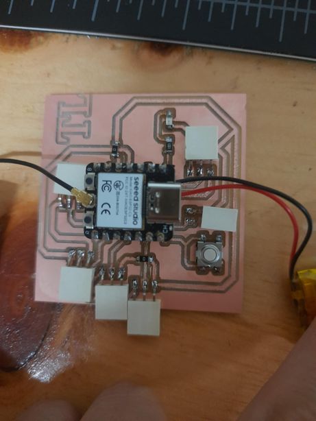
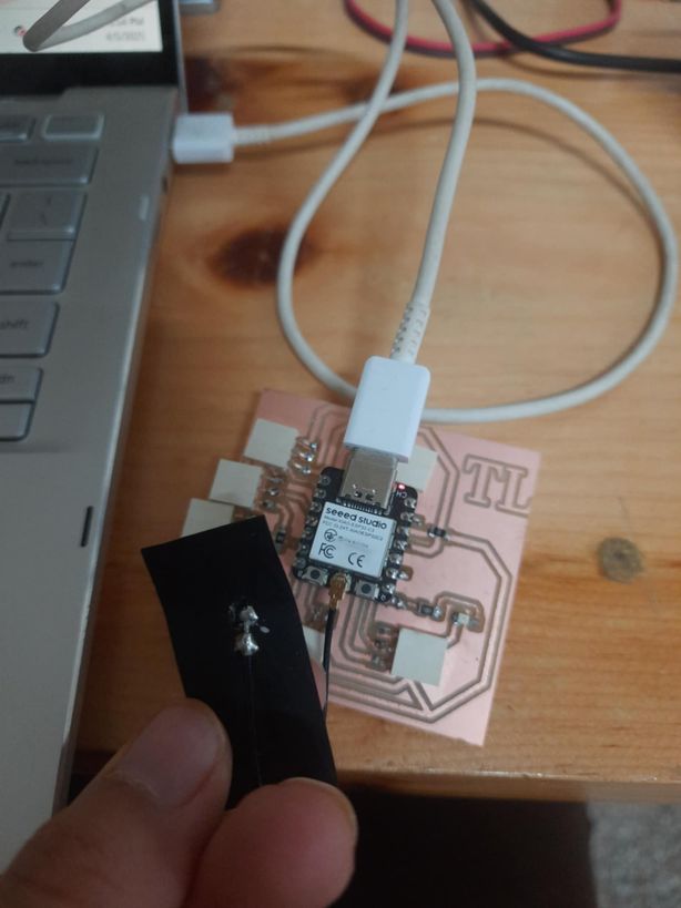
NOTE: These codes are from SeedStudio's official page as I followed this official page for my microcontroller. I started off by connecting my Bluetooth/WiFi antenna with the board that I had created during Electronics Production Week,and copy pasting this code and scanned the nearby Wi-fi networks
                        #include <WiFi.h>

                        void setup() {
                            Serial.begin(115200);

                            // Set WiFi to station mode and disconnect from an AP if it was previously connected
                            WiFi.mode(WIFI_STA);
                            WiFi.disconnect();
                            delay(100);

                            Serial.println("Setup done");
                        }

                        void loop() {
                            Serial.println("scan start");

                            // WiFi.scanNetworks will return the number of networks found
                            int n = WiFi.scanNetworks();
                            Serial.println("scan done");
                            if (n == 0) {
                                Serial.println("no networks found");
                            } else {
                                Serial.print(n);
                                Serial.println(" networks found");
                                for (int i = 0; i < n; ++i) {
                                    // Print SSID and RSSI for each network found
                                    Serial.print(i + 1);
                                    Serial.print(": ");
                                    Serial.print(WiFi.SSID(i));
                                    Serial.print(" (");
                                    Serial.print(WiFi.RSSI(i));
                                    Serial.print(")");
                                    Serial.println((WiFi.encryptionType(i) == WIFI_AUTH_OPEN) ? " " : "*");
                                    delay(10);
                                }
                            }
                            Serial.println("");

                            // Wait a bit before scanning again
                            delay(5000);
                        }
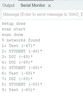
It is used to run on an ESP32 board and performs Wi-Fi network scanning. It begins by including
the WiFi.h library for managing Wi-Fi functions. In the setup() function, serial communication
is started at 115200 baud, and the Wi-Fi mode is set to station (WIFI_STA) so the ESP32 acts as a
Wi-Fi client (not an access point). It also ensures disconnection from any previous networks to
start fresh.
In the loop(), the program initiates a Wi-Fi scan using WiFi.scanNetworks(), which
searches for available Wi-Fi networks and returns the count. If no networks are found, it prints
"no networks found"; otherwise, it lists the SSID (network name), RSSI (signal strength), and
whether the network is open or encrypted (* indicates encryption). A delay of 5 seconds is added
before the next scan. This sketch is useful for checking nearby Wi-Fi networks and assessing
their signal quality.
Then in the serial monitor, you will to see the nearby networks.
                        #include <WiFi.h>

                        const char* ssid = "your-ssid";
                        const char* password = "your-password";

                        void setup() {
                            Serial.begin(115200);
                            delay(10);

                            // We start by connecting to a WiFi network

                            Serial.println();
                            Serial.println();
                            Serial.print("Connecting to ");
                            Serial.println(ssid);

                            WiFi.begin(ssid, password);

                            while (WiFi.status() != WL_CONNECTED) {
                                delay(500);
                                Serial.print(".");
                            }

                            Serial.println("");
                            Serial.println("WiFi connected");
                            Serial.println("IP address: ");
                            Serial.println(WiFi.localIP());
                        }

                        void loop() {}
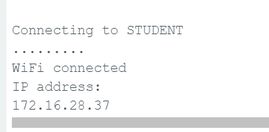
This code connects an ESP32 board to a Wi-Fi network using the WiFi.h library just like before It
defines the SSID and password of the target network, then attempts to connect during the
setup() function.
WiFi.begin(ssid, password); starts connecting to the specified Wi-Fi network.
A while loop keeps checking the connection status with WiFi.status() != WL_CONNECTED and prints
dots every 500 ms until connected.
Once connected, it prints "WiFi connected" and displays the device’s local IP address using
WiFi.localIP().
The loop() function is empty because the connection process only needs to happen once during
setup.
Then in the serial monitor, you should see this.
I generated a code using Chatgpt-AI using the prompt "Give me two separate ESP32 Arduino sketches: One to control an LED connected to GPIO 20 using a web interface with two buttons — one purple (for ON) and one lavender (for OFF). Another to control an LED connected to GPIO 3 using serial input — type '1' to turn it ON and '0' to turn it OFF. Include serial feedback messages."**" For this week, I planned on controlling my board with a web server and for that I referred to Thinley Wozer's documentation. It actually helped me a lot as he also did something very similar whereby he connected to 2 LEDs.
                        #include <WiFi.h>
                        #include <WebServer.h>

                        const char* ssid = "your-ssid";
                        const char* password = "your-password";

                        WebServer server(80);

                        const int ledPin1 = 20; // GPIO pin for LED 1

                        void setup() {
                            pinMode(ledPin1, OUTPUT);

                            Serial.begin(115200);
                            Serial.println();
                            Serial.println("Connecting to Wi-Fi");

                            WiFi.begin(ssid, password);
                            while (WiFi.status() != WL_CONNECTED) {
                                delay(1000);
                                Serial.print(".");
                            }

                            Serial.println("");
                            Serial.println("WiFi connected");
                            Serial.println("IP address: ");
                            Serial.println(WiFi.localIP());

                            String html = "<html><head><style>";
                            html += "body { font-family: Arial, sans-serif; background-color: #957dad; color: #ffffff; margin: 0; padding: 0; }";
                            html += "h1 { text-align: center; margin-top: 50px; }";
                            html += "h2 { text-align: center; }";
                            html += "button { display: block; margin: 20px auto; padding: 10px 20px; font-size: 18px; background-color: #5e5874; border: none; border-radius: 5px; color: #ffffff; cursor: pointer; }";
                            html += "button:hover { background-color: #7d75a2; }";
                            html += "</style></head><body>";
                            html += "<h1>ESP32 Web Server</h1>";
                            html += "<h2>HELLO LED-I am going to control you little thing! MWAHAHAH!</h2>";
                            html += "<button onclick=\"fetch('/on1')\">Turn On</button>";
                            html += "<button onclick=\"fetch('/off1')\">Turn Off</button>";
                            html += "</body></html>";

                            server.on("/", HTTP_GET, [html]() {
                                server.send(200, "text/html", html);
                            });

                            server.on("/on1", HTTP_GET, []() {
                                digitalWrite(ledPin1, HIGH);
                                server.send(200, "text/plain", "LED 1 turned on");
                            });

                            server.on("/off1", HTTP_GET, []() {
                                digitalWrite(ledPin1, LOW);
                                server.send(200, "text/plain", "LED 1 turned off");
                            });

                            server.begin();
                            Serial.println("HTTP server started");
                        }

                        void loop() {
                            server.handleClient();
                        }
This code sets up a web server that lets you control an LED via a web page. It uses the WiFi.h
and WebServer.h libraries.
Wi-Fi Setup: It connects the ESP32 to a Wi-Fi network using the given SSID and password. The
IP address is printed once connected.
Web Server: A simple web server runs on port 80 (WebServer server(80);). It serves an HTML page
when a user visits the root URL ("/"). The page includes styled text and two buttons labeled
“Turn On” and “Turn Off.”
LED Control: The buttons call endpoints /on1 and /off1:
/on1 turns on the LED connected to GPIO 20.
/off1 turns it off.
Each action sends back a plain text confirmation like “LED 1 turned on”.
                        #define LED_PIN 3 // Change this to your desired output pin

                        void setup() {
                            Serial.begin(9600); // Start serial communication at 9600 baud rate
                            pinMode(LED_PIN, OUTPUT); // Set LED pin as output
                        }

                        void loop() {
                            if (Serial.available() > 0) {
                                char receivedChar = Serial.read(); // Read the incoming byte

                                // Check the received character and control the LED accordingly
                                if (receivedChar == '1') {
                                    digitalWrite(LED_PIN, HIGH); // Turn the LED on
                                    Serial.println("LED ON");
                                } else if (receivedChar == '0') {
                                    digitalWrite(LED_PIN, LOW); // Turn the LED off
                                    Serial.println("LED OFF");
                                }
                            }
                        }
Explanation of My Web Server Code
IP Address
The IP address that I see printed in the serial monitor (for example, 192.168.1.100) is the local network address assigned to my ESP32 by my Wi-Fi router. Unlike a domain name like google.com, which points to a public IP address on the internet, this local IP address is only valid within my home or local Wi-Fi network.
When I connect to this IP address in my browser, I am accessing a web server running directly on my ESP32. My computer and the ESP32 communicate within the same local network.
Why Not a Website Like google.com?
Google.com is a domain name that points to Google’s servers on the internet. My ESP32 acts as a small, local web server. It doesn’t have a domain name or public IP registered online; it’s only accessible within my home or local Wi-Fi network using the IP address assigned by my router.
What Happens When I Press the "On" Button?
- When I click the HTML button, its
onclickevent triggers a JavaScriptfetch()request to the endpoint/on1. - This sends an HTTP GET request to my ESP32’s local web server.
- In my ESP32 code, I have:
server.on("/on1", HTTP_GET, []() { ... });which listens for this request. - When the
/on1request is received, my ESP32 executes the code:digitalWrite(ledPin1, HIGH);— which turns the LED on.server.send(200, "text/plain", "LED 1 turned on");— which sends a response back.
- This response can be seen in my browser’s developer tools but doesn’t show up in the main browser window.
What Is an Endpoint?
An endpoint is a specific path or URL on a web server that performs a defined function. In my code, /, /on1, and /off1 are endpoints that trigger different actions on my ESP32.
How Does the Server Know Which Code to Run?
The server.on() function maps each endpoint to its specific behavior. For example:
server.on("/on1", HTTP_GET, []() {
  digitalWrite(ledPin1, HIGH);
  server.send(200, "text/plain", "LED 1 turned on");
});
This code tells the server to execute the block inside the curly braces when it receives a GET request to /on1. The server.handleClient() function in the loop() continually checks for incoming client requests and dispatches them to the appropriate handler based on the endpoint.
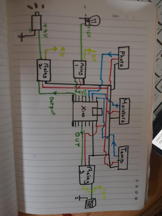
Final Project Development
I sent a diagram for my electrical connections for the week and then Sir Rico gave me useful suggestions and advices. He told me that I had connected the relay in the wrong way.
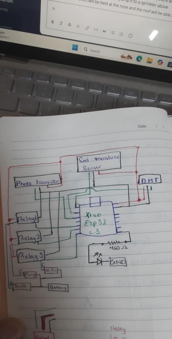
These were his explanations : "The wires from the MCU will be VCC, GND and Signal...to the Relay.
From the Relay...there will be a wire in from a power source (+) and a wire out to the device
(Motor, Pump, LED) that is also the + wire. The GND wire goes from power source directly to the
device."
"basically...the + wire from the power source is 'interrupted' by the relay (switch).
the microcontroller sends an ON or OFF signal via the signal wire to allow the 'interruption' to
connect or disconnect. The VCC and GND wire to the Relay is to power the Relay module"
He sent
me these 2 pictures so I could vidualize and understand better too
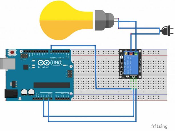
Then he sent me a refined diagram for my electrical components which has helped me understand about the connections better. Thank you Rico san!!!
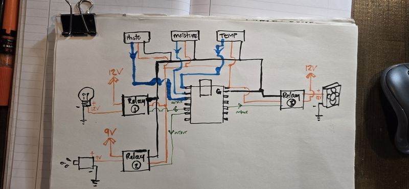
Then I redrew my electronics diagram which then helped me get a better visualization of how my final PCB would look like.