
Roadmap
This week started with me making a roadmap as to see my progress. This week we are learning embedded programming and lots of new words were thrown at us and then the course started to pick its pace pretty fast. You can check out the vocabularies and software section if they are also new to you.
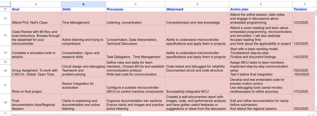
Table of Contents
- Group Assignment
- Individual Assignment
- Final Project Development
- pin: The GPIO number you want to configure.
- mode: Defines how the pin behaves. The available modes are:
- INPUT: Configures the pin to receive signals.
- OUTPUT: Allows the pin to send signals (e.g., turning an LED on/off).
Assignments
Group Assignment :
-Compare the performance and development workflows for other architectures
Document your work to the group work page and reflect on your individual page what you learned
Individual Assignment:
-Use either TinkerCAD circuits...or Wokwi...to build a simple circuit (ex: LED light)...and write a simple program to have the circuit do something (ex: blink an LED)
-Browse through the datasheet for your microcontroller
Individual Assignment
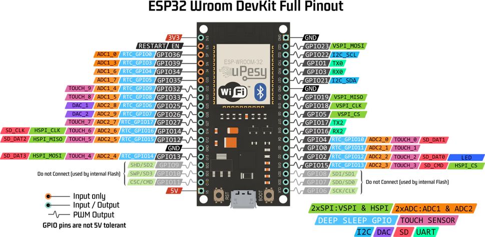
Mr.Rico and Madam Wangzom taught us a lot during our local session and handed us thislink through which we learned a lot. For the individual assignment for this week, I browsed though the data sheet of the microcontroller that I chose which was ESP32. I chose it because of its built-in Wi-Fi, allowing remote monitoring. It also supports multiple sensors, has low power consumption, and offers high processing power for automation.
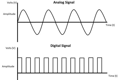
Before browsing the datasheet, we must understand analog and digital signals. You can think of a digital signal as a switch-which has only 2 states- either on or off. In contrast think of analogue signal like a smooth wave, just like your voice when you sing or the way a river flows. It changes gently and can have any value in between.
There are 34 GPIO pins in ESP32 but only 18 of them are for analogue signals which is helpful for sensors like temperature, light, and moisture sensors.
It is also important to know that VCC is the positive terminal and is connected to the positive side (anode) of a circuit component, while GND is the negative terminal and serves as the zero voltage reference point, connecting to the negative side (cathode).
This is the datasheet that I browsed though. The image below was downloaded from this link.
I learned quite a lot about the functionalities of ESP32 and some of the amazing applications that it has are: Smart Home, Industrial Automation, Health Care, and Smart Agriculture.
Some of the important takeaways that I had were it had:
Microcontroller: Dual-core Tensilica Xtensa LX6 microprocessor (up to 240 MHz). Offers excellent performance for running application code and managing wireless connectivity.
integrated Wi-Fi: 802.11 b/g/n (2.4 GHz), up to 150 Mbps and 520 KB SRAM (for program execution and data storage).
Bluetooth;Bluetooth v4.2 BR/EDR and Bluetooth Low Energy (BLE). Enables short-range communication with other devices.
power efficient-• Ultra-Low-Power (ULP) coprocessors
lots of memory-448 KB ROM (for boot code and core functions) and
lots of peripherals with 34 programmable GPIOs to enable input, output, communication, and storage functions making it suitable for a wide variety of projects with a wide variety of sensors and actuators.
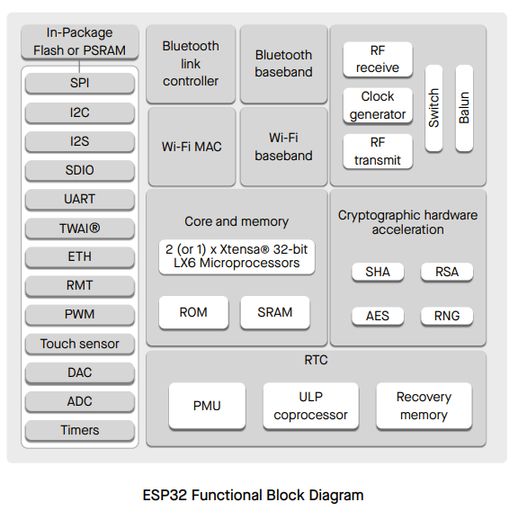
This is the functional block of ESP32.
About PinMode
Before delving any deeper into any of it, we must understand about the pinMode() properly. The pinMode() function is one of the most important commands when working with microcontrollers like the ESP32. It sets the mode of a GPIO (General Purpose Input/Output) pin, determining whether it should act as an input or output. The syntax is "pinMode(pin, mode);"
                        Example:
If you want to blink an LED connected to GPIO2, you first set the pin as an output:
void setup() {
  pinMode(2, OUTPUT); // Configures GPIO2 as an output
}

void loop() {
  digitalWrite(2, HIGH); // Turns LED on
  delay(1000);           // Waits 1 second
  digitalWrite(2, LOW);  // Turns LED off
  delay(1000);           // Waits 1 second
}
The manual didn't contain why it was called ESP32 so I asked AI-Gemini and the prompt was "Why is ESP32 called ESP32?" and it replied
"The ESP32 gets its name from a combination of factors related to its features and heritage:ESP: This prefix comes from Espressif, the company that developed the chip. It's a common practice for companies to use a consistent prefix for their product lines.32: This part of the name refers to the 32-bit architecture of the chip's processor. This signifies that the ESP32 has a 32-bit processor, which is a common standard in modern microcontrollers, allowing for efficient data processing and memory management."
The next assignment was to create a simulation of a blinking LED in Wokwi or Tinkercad and I watched a couple of links before starting to work on the assignment.
- Arduino 101- Crash Course w/ Mark Rober
- Arduino Workshop - Chapter One - What is a Microcontroller?
- What is a microcontroller? ft. Raspberry Pi Pico
- LEDs & Breadboards With Arduino in Tinkercad
- LESSON 1:How To Easily Code LED By Using Arduino Simulator || FAST Tutorial || Wokwi
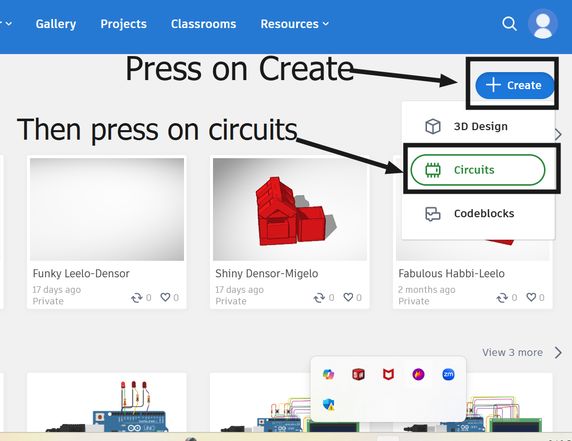
If you dont have a tinkercad account-well then you need to create an account and start working on your simulation. For starters who are wondering what it is, it is a open software-meaning it is free and it is user friendly for 3D design, electronics, and coding. You can sign in or log in here
What I did was:
I created a new project and selected circuit.
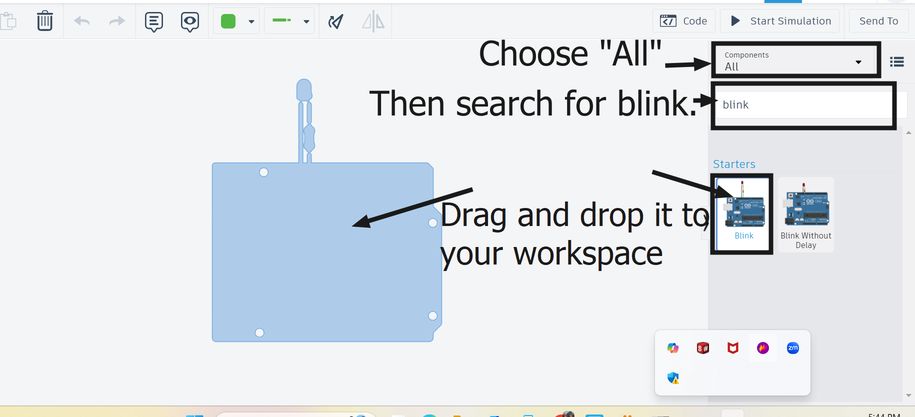
There was a builtin code for the blink simulation in tinkercad and there were comprehensible comments too. However I wanted to experiement further with it.
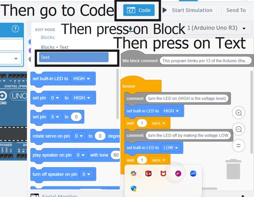
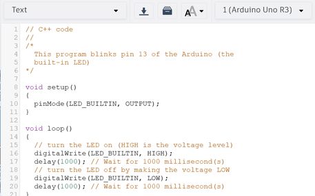
The Code generated by AI
I wanted to further this simulation by adding a few more LED bulbs so I asked AI-Deepseek to create a code to blink 2 LEDs alternatively taht were connected to pin 13 and 10. I copied the code in Tinkercad LED simulation and pasted it there and gave the prompt which was "edit this code to blink 2 LEDs connected to pin 13 and 10 alternatively with a delay of 1 seconds and provide the explanation."
/*
  This program blinks two LEDs alternately.
  LED 1 is connected to pin 13.
  LED 2 is connected to pin 10.
*/

void setup() {
  pinMode(13, OUTPUT);  // Set pin 13 as an OUTPUT
  pinMode(10, OUTPUT);  // Set pin 10 as an OUTPUT
}

void loop() {
  digitalWrite(13, HIGH);  // Turn LED 1 on
  digitalWrite(10, LOW);   // Turn LED 2 off
  delay(1000);             // Wait for 1000 milliseconds (1 second)

  digitalWrite(13, LOW);    // Turn LED 1 off
  digitalWrite(10, HIGH);   // Turn LED 2 on
  delay(1000);              // Wait for 1000 milliseconds (1 second)
}
Arduino Blinking LEDs Explanation
This program blinks two LEDs (Light Emitting Diodes) alternately.
Comments in the code (lines starting with //) are ignored by the Arduino compiler and exist only for human readability.
The setup() function runs once when the Arduino starts.
pinMode(13, OUTPUT); and pinMode(10, OUTPUT); set pins 13 and 10 as output pins to control the LEDs.
The loop() function runs repeatedly:
Turn LED 1 on and LED 2 off:
digitalWrite(13, HIGH); sends a HIGH signal (5V) to pin 13, turning LED 1 on.
digitalWrite(10, LOW); sends a LOW signal (0V) to pin 10, turning LED 2 off.
delay(1000); pauses the program for 1000 milliseconds (1 second), so LED 1 stays on for 1 second.
Turn LED 1 off and LED 2 on:
digitalWrite(13, LOW); sends a LOW signal to pin 13, turning LED 1 off.
digitalWrite(10, HIGH); sends a HIGH signal to pin 10, turning LED 2 on.
delay(1000); pauses the program for another 1 second, so LED 2 stays on for 1 second.
After this, the loop repeats, causing the two LEDs to blink alternately.
I used the same code for a circuit in Wokwi and it kind of worked too. I find Wokwi user friendly and easy to use.
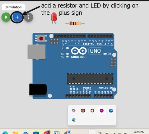
Firstly go to Wokwi website and click on it> Then on the Simulate with Wowki Online, go to Arduino Uno> Then scroll down a little bit and in the Start from Scratch>choose Arduino Uno
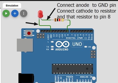
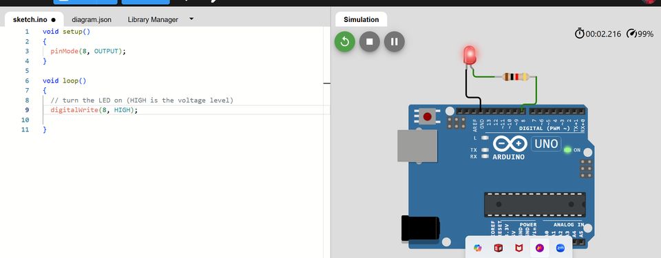
Then add a resistor and an LED and connect them to GND and a pinout respectively.
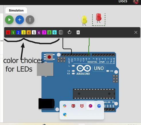
Another fun feature is that you can choose the colors of the LED so I chose it and wrote a simple code and Yipee! The LED blinked
Then I added some more LEDs and resistors and copied and pasted the code in tinkercad and Whoo! It worked again!
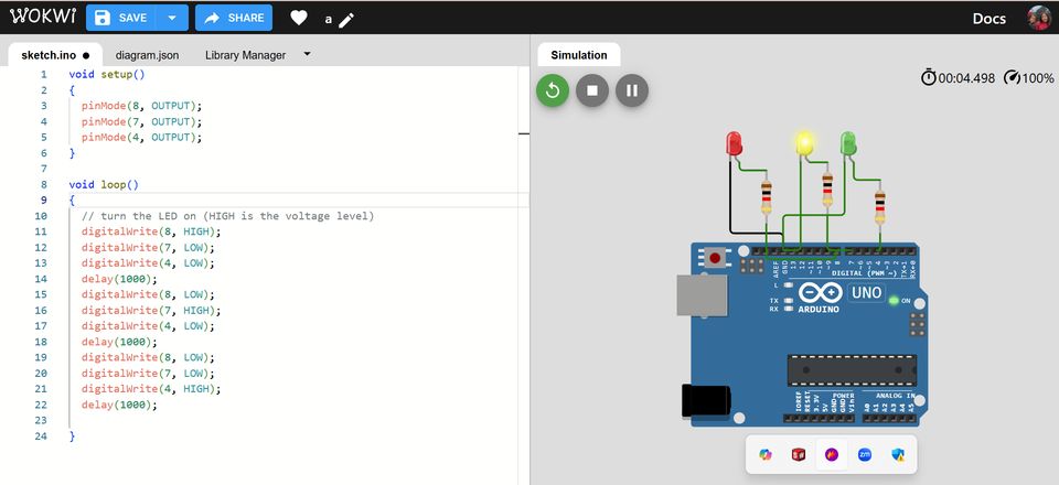
This is the final code that I edited from the already given code in tinkercad simulation for LED blink.
void setup() {
  pinMode(13, OUTPUT);  // Set pin 13 as an OUTPUT
  pinMode(10, OUTPUT);  // Set pin 10 as an OUTPUT
  pinMode(6, OUTPUT);
}

void loop() {
  digitalWrite(13, HIGH);  // Turn LED 1 on
  digitalWrite(10, LOW); // Turn LED 2 off
  digitalWrite(6, LOW);  // Turn LED 3 off
  delay(1000);  // Wait for 1000 milliseconds (1 second)

  digitalWrite(13, LOW);  // Turn LED 1 off
  digitalWrite(10, HIGH); // Turn LED 2 on
  digitalWrite(6, LOW);  // Turn LED 3 off
  delay(1000);

  digitalWrite(13, LOW);  // Turn LED 1 off
  digitalWrite(10, LOW); // Turn LED 3 off
  digitalWrite(6, HIGH);  // Turn LED 3 on
  delay(1000);
}
Group Assignment:Comparison
This week, we had to use the Arduino IDE to write code, compile, debug and to upload it to the board.The boards that we look forward to test for this group assignments are:Arduino Uno, ATTINY 44 and Esp32. You can access the group assignment here
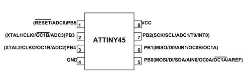
ATTINY45 is an 8 bit controller based on Advanced RISC architecture. It is a compact, cost-effective 8-pin AVR microcontroller with 4KB program memory. It is popular due to its low cost and small size despite having fewer pins.s attiny45
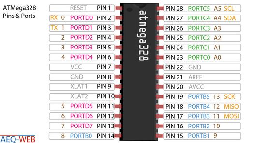
I also wanted to learn about ATmega328 so I researched for it too. The ATmega328P (AVR) is an 8-bit RISC microcontroller running at 16 MHz, with limited resources (2 KB RAM, 32 KB Flash), making it suitable for simple applications but lacking high-speed performance. This is the image
ESP32 (Xtensa LX6/LX7) is a dual-core 32-bit microcontroller with clock speeds up to 240 MHz, built-in WiFi/Bluetooth, and significantly more memory (320 KB RAM, 4MB+ Flash), making it ideal for IoT and wireless applications. ESP32 (Xtensa LX6/LX7)
Final Project Development
During this week we learned circuit simulation and browsed through the datasheet for our micro controllers. To make tiny little baby steps, I followed a tutorial, and simulated a circuit that prints the readings from the LDR[Light Dependent Resistor.]
Firstly go to Wokwi and choose Arduino Uno and start from scratch
Then press on the plus button and add an LDR
Connect the following terminals as given in the diagram
Then when you press on the red box that is circled, you can manipulate the illumination so the readings would be different.
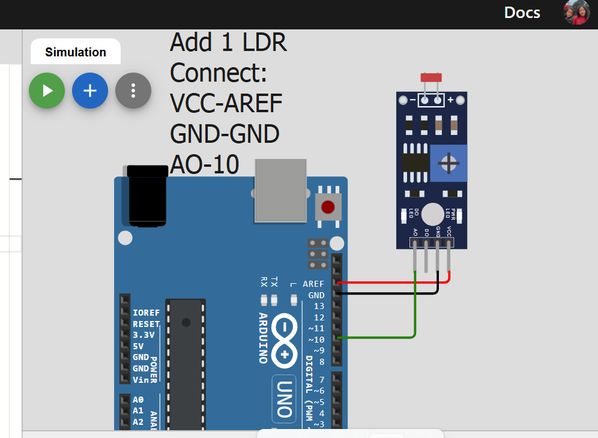
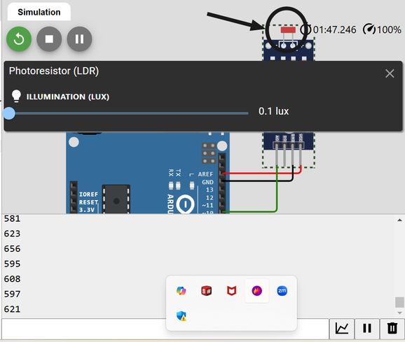
We have to connect AO to a GPIO because our data is analogue and is continuous. While coding too, we have to set that GPIO as our INPUT. The code that I wrote after watching the tutorial is given below:
NOTE: I asked AI[chatgpt] to write me the code to enclose the following code into a clickable button. I copied the code and pasted it in the chat and the prompt was "Modify the code to enclose the following in a clickable button that will open and hide it when clicked."
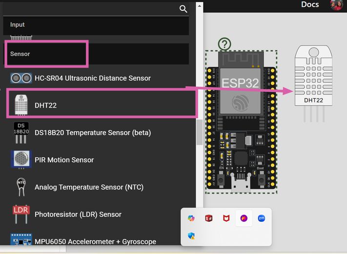
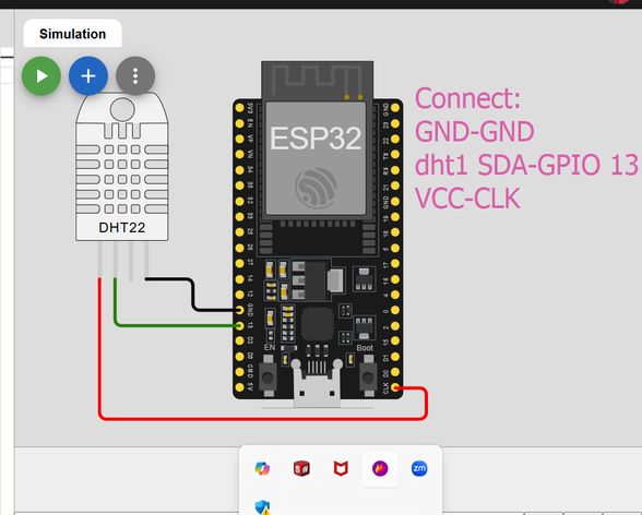
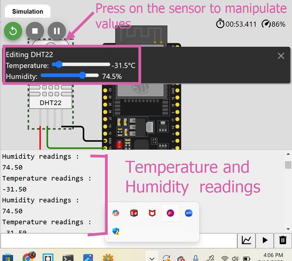
Then i also wanted to try simulating the DHT22 sensor and for that I referred to this tutorial. This time instead of Arduino Uno board, I chose to work on ESP32.
Firstly presss the plus(+) button and then scroll down to inputs and select DHT22 sensor.
Next connect the following.
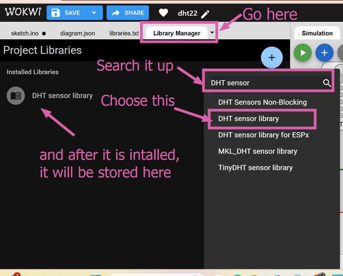
Then go to the library manager and search up DHT sensor and then download DHT sensor library and then it will be installed. The library provides predefined functions to make communication with the sensor easier.
When you press on the sensor, you will be able to manipulate the humidity and temperatures value.
Then you can simulate it and the temperature and the humidity readings will be displayed.
NOTE: I asked AI[chatgpt] to write me the code to enclose the following code into a clickable button. I copied the code and pasted it in the chat and the prompt was "Modify the code to enclose the following in a clickable button that will open and hide it when clicked."
PS I mostly write the code in html myself because I am learning along the way but sometimes for debugging reasons, i seek the help of AI such as Chatgpt, Deepseek and Copilot