Parametric Construction Kit
The mission of the week assignment is to design a parametric construction kit which can be assembled in multiple ways.
Basic design in CorelDraw
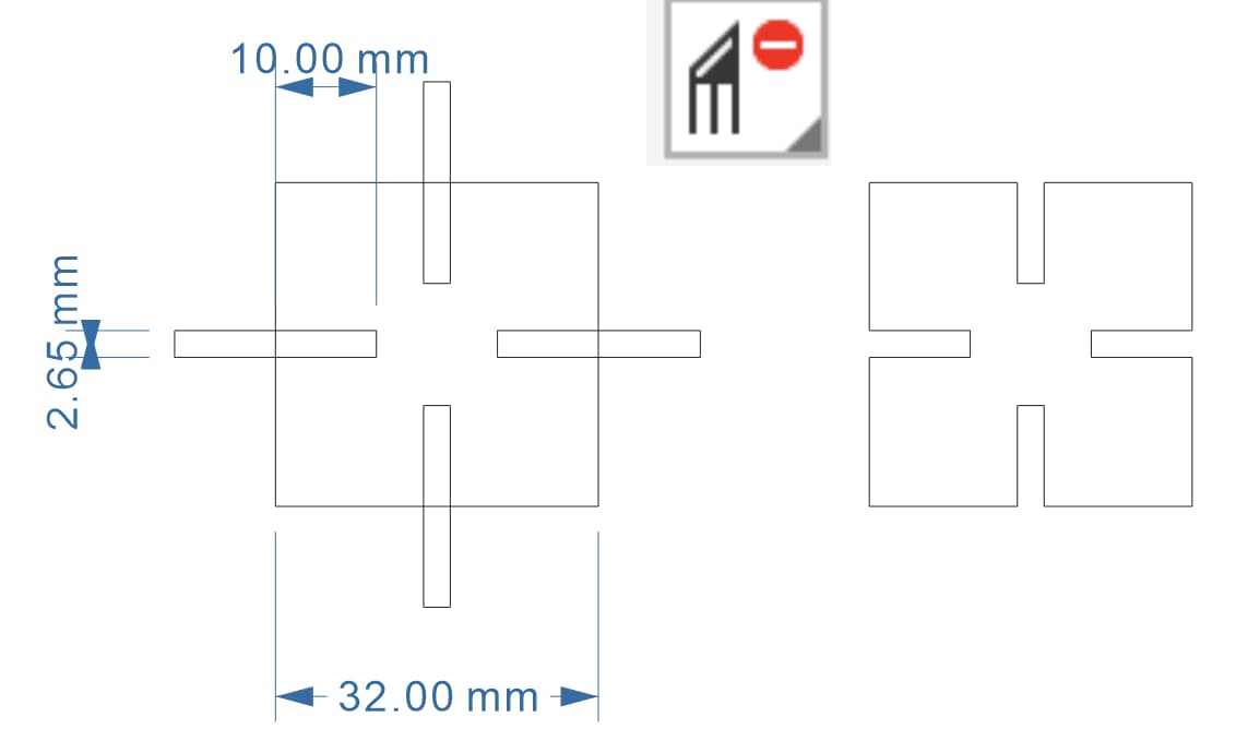
I plan to design a square with grooves as a prototype in CorelDraw. The material I choose is 3mm board. Acrossing to the kerf result in group project, the kerf is about 0.35mm for 3mm board, so I set the thickness as 2.65mm for the connection part. The length of the square is design as 32mm and the depth of the grooves is 10mm. The result is here:
Design with parameter in Fusion360
Process
- In fusion360, we can call the parameter modification function by press the hotkey
sand searchChange Parameters.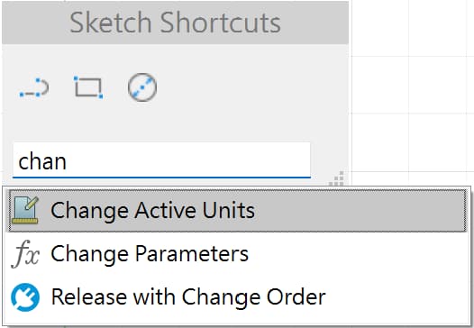
- The parameters are set as below. The size of the design is remain the same as in CorelDraw, but I want to set thepe can be modified to other regular polygons, so I also add a parameter call side.
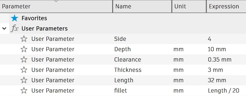
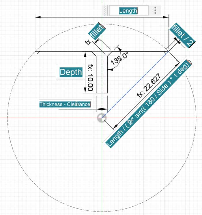
- Sketch the shape of the design. In fusion360, I only need to draw one side of the polygon and just rotate it to build the whole polygon. And remember to enter dimension with parameter instead of entering the fixed size number.
- Select the outer line, then use
Circular pattern(hollow one) to complete the whole shape. Set theQuantitybe parameterside.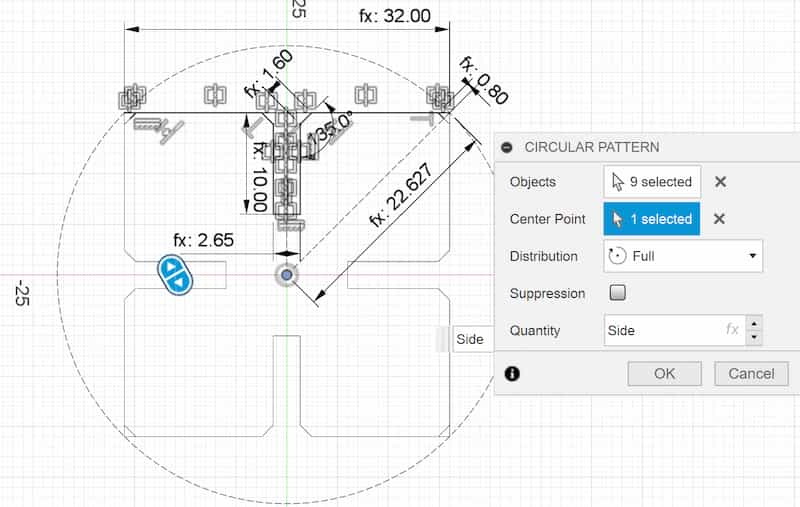
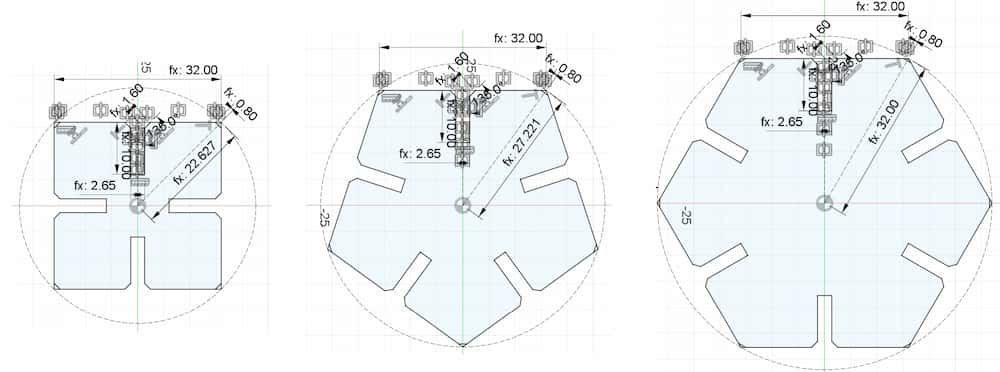
- To test the shape in different side, I change the
sideparameter from 4 to 5 and 6 inChange Parameters.
Laser cut
By compare the size of the the 3 version above, the hexagon one is a little too big for mass production. So I only choose the square and pentagon version is cut. As the laser cutter in my lab is compatible to CorelDraw, so the following step is controlled in CorelDraw.
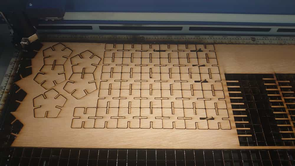
- Place the polygons together as close as possible to minimize material waste.
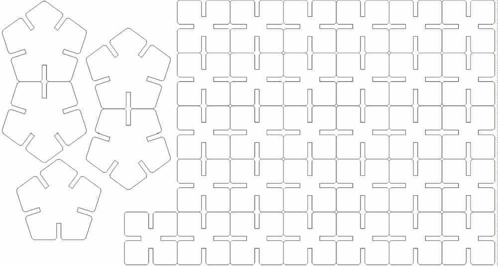
Ideally, the shapes should be placed edge to edge to effectively reduce space and save time.
It's important to delete overlapping lines, confrim to leave only one, otherwise the overlapping parts will be cut multiple times by the laser cutter, which could cause a fire!
-
Laser cutting
-
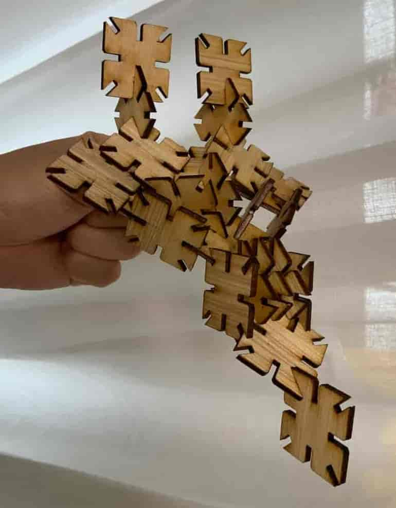
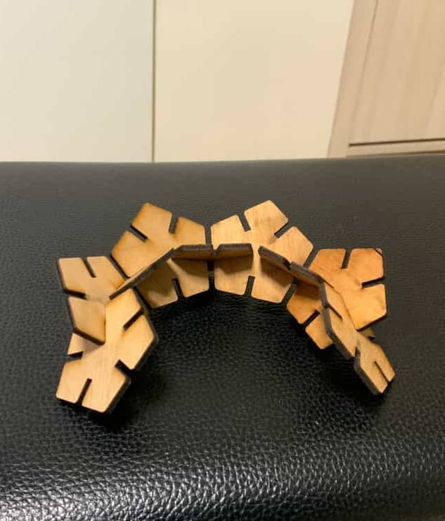
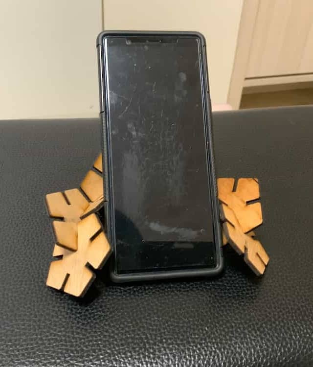
Testing the result. The pentagon version is fit perfect! And it can be used as a phone stand.
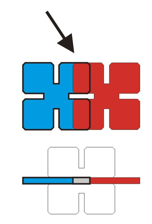
But the square version has a problem. The depth of the connection part is too depth, they will
conflict when the more than 2 parts are connected. As the depth is fixed in the Fusion360 design, it only affect the square version, don't affect the version with side large than 4.
Upgrade the design
Upgrade
-
I set a new parameter
NewDepthin the Fusion360 design, which will change depend on the length.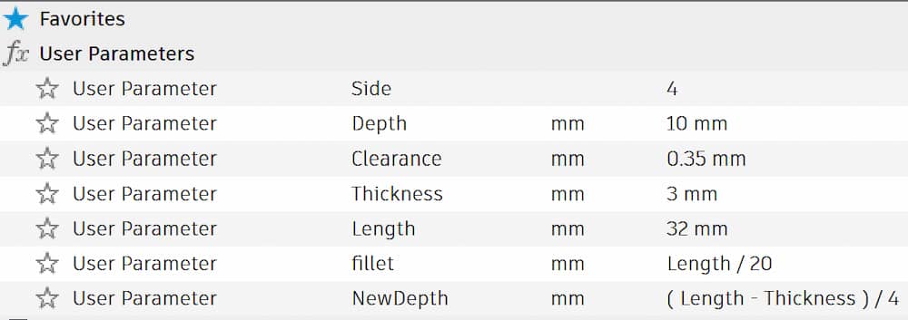
-
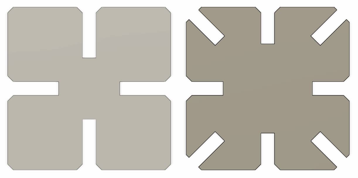
To increase the variability of the parts, I added four more grooves in the corners.
-
Compare the two version
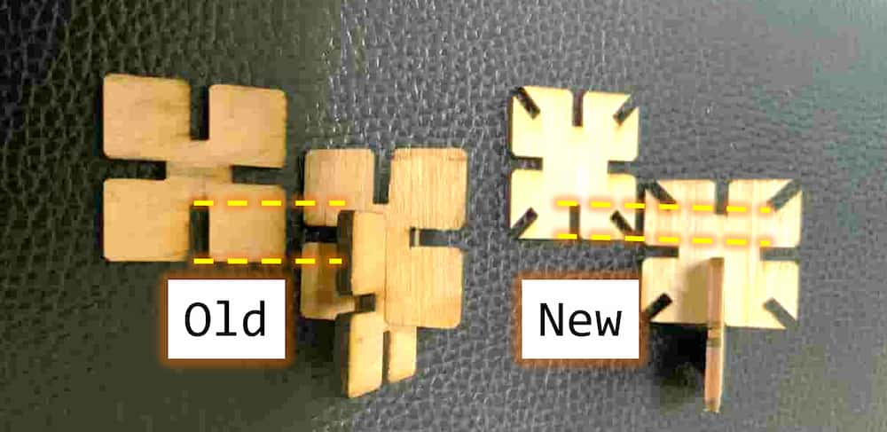
Test the result!