Week4 - Arduino & IDF
Arduino & ESP IDF
I will compare Arduino IDE and ESP IDF in this assignment.
Arduino IDE
Arduino is an open-source electronics platform based on easy-to-use hardware and software. Arduino boards are able to read inputs - light on a sensor, a finger on a button, or a Twitter message - and turn it into an output - activating a motor, turning on an LED, publishing something online. You can tell your board what to do by sending a set of instructions to the microcontroller on the board. To do so you use the Arduino programming language (based on Wiring), and the Arduino Software (IDE), based on Processing.
Install Arduino IDE
To install Arduino IDE, you can follow this instructions.
Install ESP32 Board in Arduino IDE
- Click
File->Preferences - In the
Additional Boards Manager URLs, insert the following URL:
https://raw.githubusercontent.com/espressif/arduino-esp32/gh-pages/package_esp32_index.json
- Click
Tools->Boards->Board Manager - Search
esp32and install
Upload a Sketch
- Choose
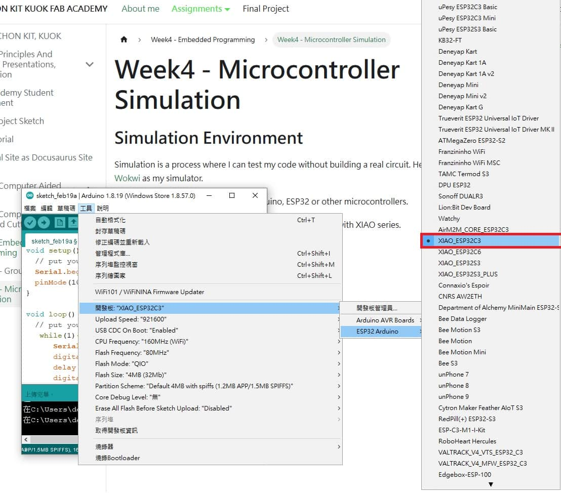
XIAO ESP32C3board fromTools->Board.
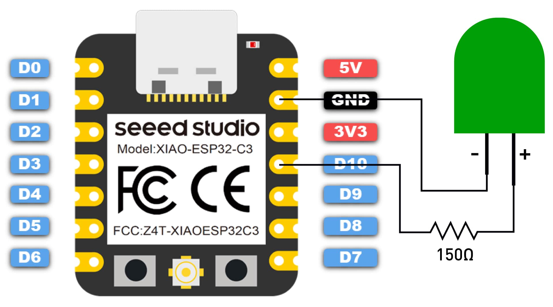
Refer the Getting Started tutorial here, I tried to build up a simple LED circuit with ESP32C3 board and upload the following program to the board, which is drive the LED with D10 pin.
void setup() {
  // put your setup code here, to run once:
  Serial.begin(115200);
  pinMode(10, OUTPUT);
}

void loop() {
  // put your main code here, to run repeatedly:
   while(1){
      Serial.println("hello, fab academy");
      digitalWrite(10, HIGH);
      delay(1000);
      digitalWrite(10, LOW);
      delay(1000);
   }
}
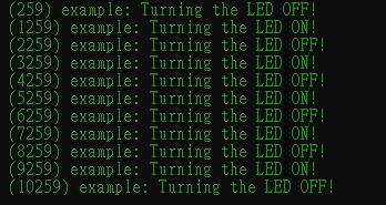
After uploading the sketch, you can see the following output:
ESP IDF
I refer the instuctions here.
In my case, I use Windows System.
Install ESP-IDF
Go to here and download the installer.
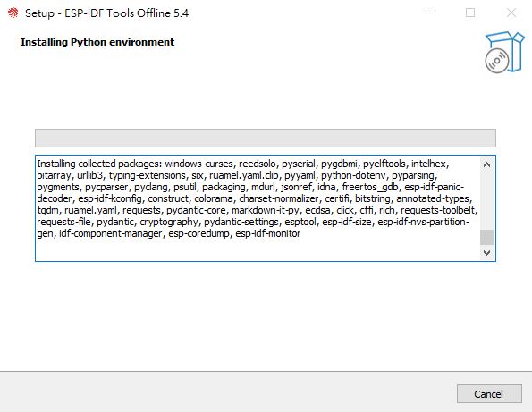
Then, I choose ESP-IDF v5.4 - Offline Installer.
Setup the tools
cd ~/Espressif\frameworks\esp-idf-v5.4
install.sh
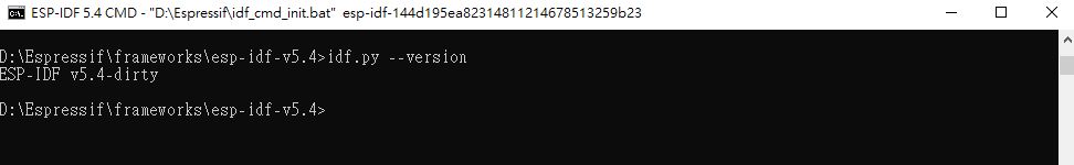
Test the installation
idf.py --version
Flash a example project
Then, let us build a blink example.
We will use ESP-IDF 5.4 POWERSHELL to input the command.
Here's the code of the blink example, which's code is C++.
/* Blink Example

   This example code is in the Public Domain (or CC0 licensed, at your option.)

   Unless required by applicable law or agreed to in writing, this
   software is distributed on an "AS IS" BASIS, WITHOUT WARRANTIES OR
   CONDITIONS OF ANY KIND, either express or implied.
*/
#include <stdio.h>
#include "freertos/FreeRTOS.h"
#include "freertos/task.h"
#include "driver/gpio.h"
#include "esp_log.h"
#include "led_strip.h"
#include "sdkconfig.h"

static const char *TAG = "example";

/* Use project configuration menu (idf.py menuconfig) to choose the GPIO to blink,
   or you can edit the following line and set a number here.
*/
#define BLINK_GPIO CONFIG_BLINK_GPIO

static uint8_t s_led_state = 0;

#ifdef CONFIG_BLINK_LED_STRIP

static led_strip_handle_t led_strip;

static void blink_led(void)
{
    /* If the addressable LED is enabled */
    if (s_led_state) {
        /* Set the LED pixel using RGB from 0 (0%) to 255 (100%) for each color */
        led_strip_set_pixel(led_strip, 0, 16, 16, 16);
        /* Refresh the strip to send data */
        led_strip_refresh(led_strip);
    } else {
        /* Set all LED off to clear all pixels */
        led_strip_clear(led_strip);
    }
}

static void configure_led(void)
{
    ESP_LOGI(TAG, "Example configured to blink addressable LED!");
    /* LED strip initialization with the GPIO and pixels number*/
    led_strip_config_t strip_config = {
        .strip_gpio_num = BLINK_GPIO,
        .max_leds = 1, // at least one LED on board
    };
#if CONFIG_BLINK_LED_STRIP_BACKEND_RMT
    led_strip_rmt_config_t rmt_config = {
        .resolution_hz = 10 * 1000 * 1000, // 10MHz
        .flags.with_dma = false,
    };
    ESP_ERROR_CHECK(led_strip_new_rmt_device(&strip_config, &rmt_config, &led_strip));
#elif CONFIG_BLINK_LED_STRIP_BACKEND_SPI
    led_strip_spi_config_t spi_config = {
        .spi_bus = SPI2_HOST,
        .flags.with_dma = true,
    };
    ESP_ERROR_CHECK(led_strip_new_spi_device(&strip_config, &spi_config, &led_strip));
#else
#error "unsupported LED strip backend"
#endif
    /* Set all LED off to clear all pixels */
    led_strip_clear(led_strip);
}

#elif CONFIG_BLINK_LED_GPIO

static void blink_led(void)
{
    /* Set the GPIO level according to the state (LOW or HIGH)*/
    gpio_set_level(BLINK_GPIO, s_led_state);
}

static void configure_led(void)
{
    ESP_LOGI(TAG, "Example configured to blink GPIO LED!");
    gpio_reset_pin(BLINK_GPIO);
    /* Set the GPIO as a push/pull output */
    gpio_set_direction(BLINK_GPIO, GPIO_MODE_OUTPUT);
}

#else
#error "unsupported LED type"
#endif

void app_main(void)
{

    /* Configure the peripheral according to the LED type */
    configure_led();

    while (1) {
        ESP_LOGI(TAG, "Turning the LED %s!", s_led_state == true ? "ON" : "OFF");
        blink_led();
        /* Toggle the LED state */
        s_led_state = !s_led_state;
        vTaskDelay(CONFIG_BLINK_PERIOD / portTICK_PERIOD_MS);
    }
}
Copy the example blink project to a new folder.
from
C:\Espressif\frameworks\esp-idf-v5.4\examples\get-started\blink
to
C:\Users\denni\esp
Then, open the ESP-IDF 5.4 Powershell and go to the folder of the project.
In my case:
cd C:\Users\denni\esp\blink\
The link of the example folder.
C:\Espressif\frameworks\esp-idf-v5.4\examples\get-started\blink
Build and flash the project, in this case I use ESP32C3
idf.py set-target esp32c3
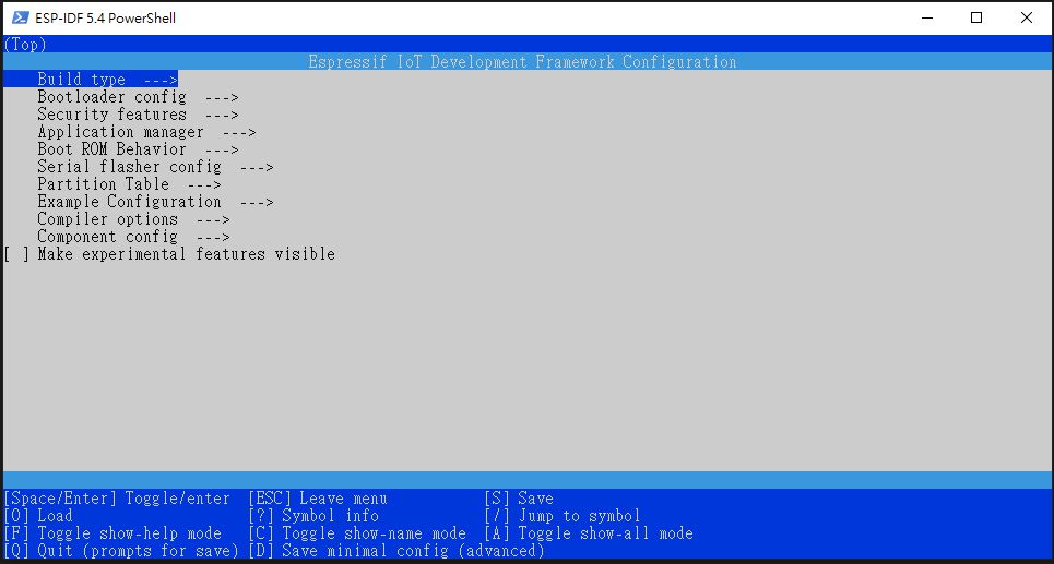
idf.py menuconfig
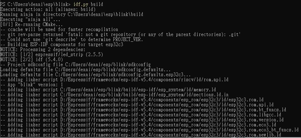
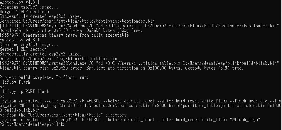
Build the project
idf.py build
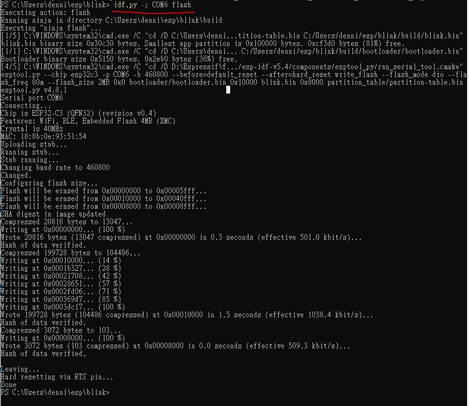
Then, flash the project to the board. In my case, COM6 is my port of the board.
idf.py -p COM6 flash
Monitor the Output
idf.py -p COM6 monitor