Week10 - Output Devices
The task of the assignment
- Add an output device to a microcontroller board you've designed, and program it to do something
Hardware will be used
Microcontroller
In this assignment, XIAO ESP32C3 will be used. Seeed Studio XIAO ESP32C3 is an IoT mini development board based on the Espressif ESP32-C3 WiFi/Bluetooth dual-mode chip, featuring a 32-bit RISC-V CPU that delivers powerful computing performance with its efficient architecture. It has excellent radio frequency performance, supporting IEEE 802.11 b/g/n WiFi, and Bluetooth 5 (BLE) protocols.
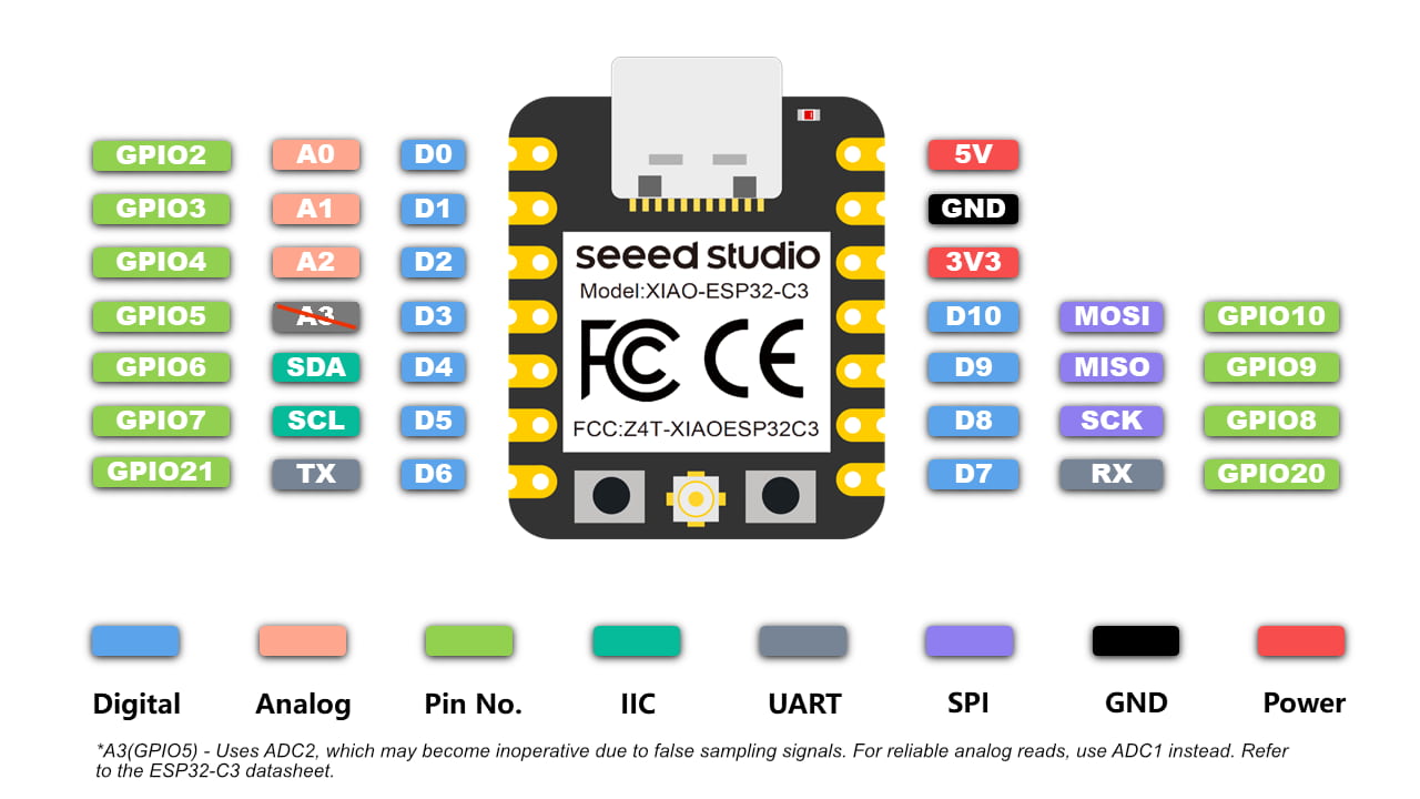
There are 10 digital IO pins, 3 analog input pins, 1 set of IIC and 1 set of SPI can be used for sensing.
I2C protocol
Ref: https://www.geeksforgeeks.org/i2c-communication-protocol/
I2C stands for Inter-Integrated Circuit. It is a bus interface connection protocol incorporated into devices for serial communication. It was originally designed by Philips Semiconductor in 1982. Recently, it is a widely used protocol for short-distance communication. It is also known as Two Wired Interface(TWI).
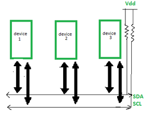
It uses only 2 bi-directional open-drain lines for data communication called SDA and SCL. Both these lines are pulled high.
- Serial Data (SDA) : Transfer of data takes place through this pin.
- Serial Clock (SCL) : It carries the clock signal.
Each data bit transferred on SDA line is synchronized by a high to the low pulse of each clock on the SCL line.
I2C LCD
Ref: https://randomnerdtutorials.com/esp32-esp8266-i2c-lcd-arduino-ide/
For this assignment I'll be using a 16×2 I2C LCD display.
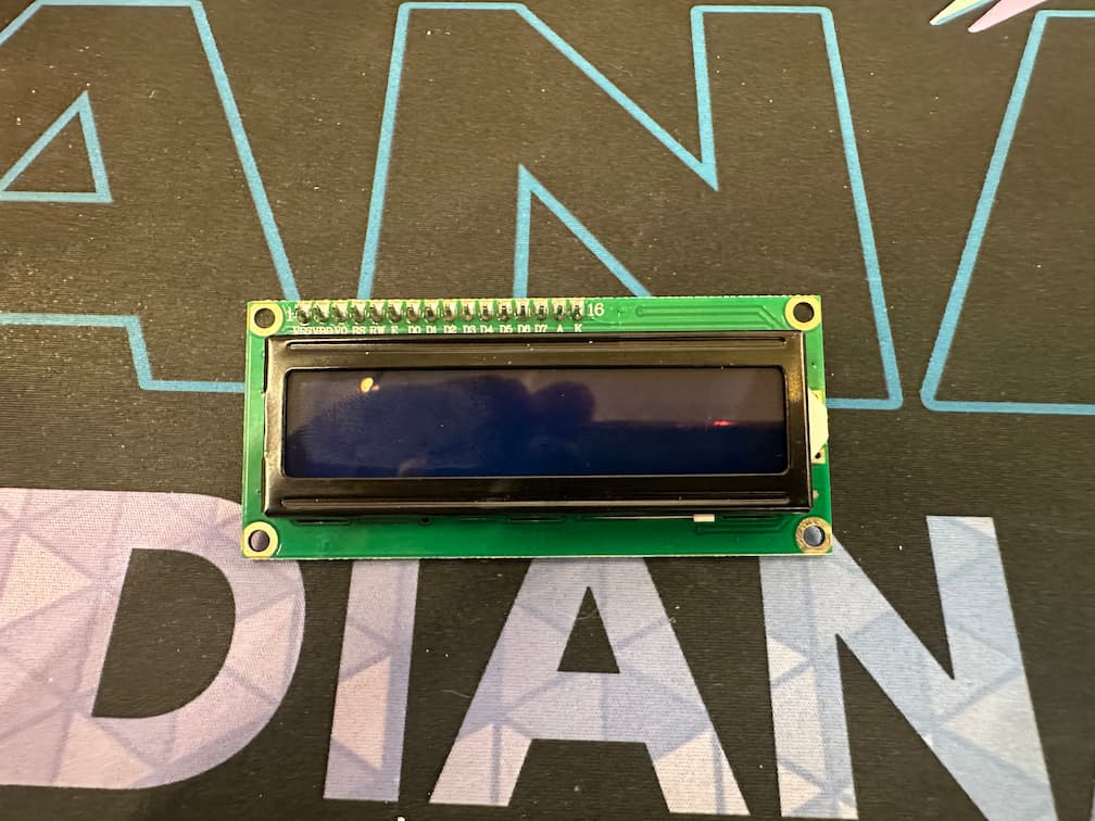
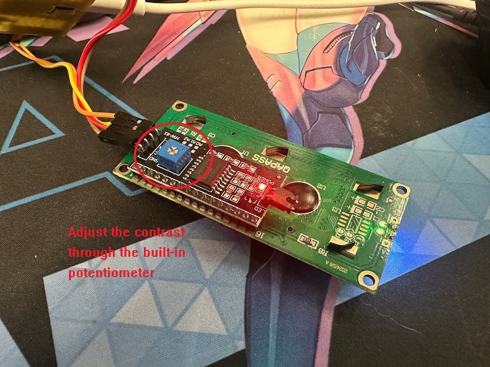
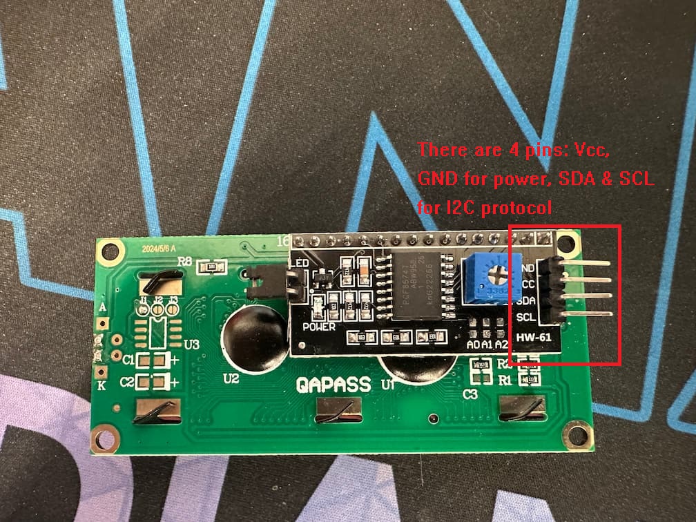
The advantage of using an I2C LCD is that the wiring is really simple. You just need to wire the SDA and SCL pins (I2C protocol).
Additionally, it comes with a built-in potentiometer you can use to adjust the contrast between the background and the characters on the LCD. On a “regular” LCD you need to add a potentiometer to the circuit to adjust the contrast.
According the pinout the XIAO ESP32C3, GPIO6 and 7 are I2C pins. Two pins will be used for wire connection.
Stepper Motor
Ref: https://lastminuteengineers.com/28byj48-stepper-motor-arduino-tutorial/
Including window blinds, 3D printers, DVD players, security cameras, and CNC machines. We’re a lot closer to stepper motors than I think.
Stepper motors fall somewhere between a conventional DC motor and a servo motor. They can rotate continuously like DC motors and be positioned precisely (in discrete steps) like servo motors.
Stepper motors use a cogged wheel and electromagnets to nudge the wheel round a ‘step’ at a time.
Each high pulse sent energizes the coil, attracting the teeth closest to the cogged wheel and rotating the motor in precise and fixed angle increments known as steps.
The number of steps that the stepper motor has in a 360 degree rotation is actually the number of teeth on the cog.
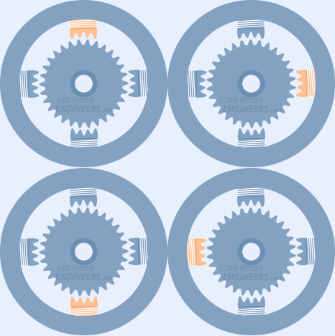
The way you pulse these coils determines how the motor operates.
- The sequence of pulses determines the spinning direction of the motor.
- The frequency of the pulses determines the speed of the motor.
- The number of pulses determines how far the motor will turn.
By energizing the coils in the correct sequence, the motor is rotated.
I2C LCD display
Simulation
I use wowki to built a simulator for I2C lcd monitor.
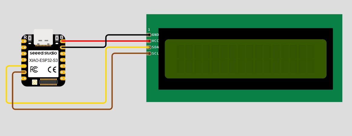
I use a demo code from randomnerdtutorials.com for testing the i2c lcd monitor. Displaying static text on the LCD is very simple. Select where I want the characters to be displayed on the screen, and then send the message to the display.
Here’s a very simple sketch example that displays “Hello, World!“.
#include <LiquidCrystal_I2C.h>

// set the LCD number of columns and rows
int lcdColumns = 16;
int lcdRows = 2;

// set LCD address, number of columns and rows
// if you don't know your display address, run an I2C scanner sketch
LiquidCrystal_I2C lcd(0x27, lcdColumns, lcdRows);

void setup(){
  // initialize LCD
  lcd.init();
  // turn on LCD backlight
  lcd.backlight();
}

void loop(){
  // set cursor to first column, first row
  lcd.setCursor(0, 0);
  // print message
  lcd.print("Hello, World!");
  delay(1000);
  // clears the display to print new message
  lcd.clear();
  // set cursor to first column, second row
  lcd.setCursor(0,1);
  lcd.print("Hello, World!");
  delay(1000);
  lcd.clear();
}
So, here’s a summary of the functions to manipulate and write on the display:
- lcd.init(): initializes the display
- lcd.backlight(): turns the LCD backlight on
- lcd.setCursor(int column, int row): sets the cursor to the specified column and row
- lcd.print(String message): displays the message on the display
- lcd.clear(): clears the display
It displays the message in the first row, and then in the second row.
Connect to real monitor & display
Then, I connect a real lcd monitor to the microcontroller.
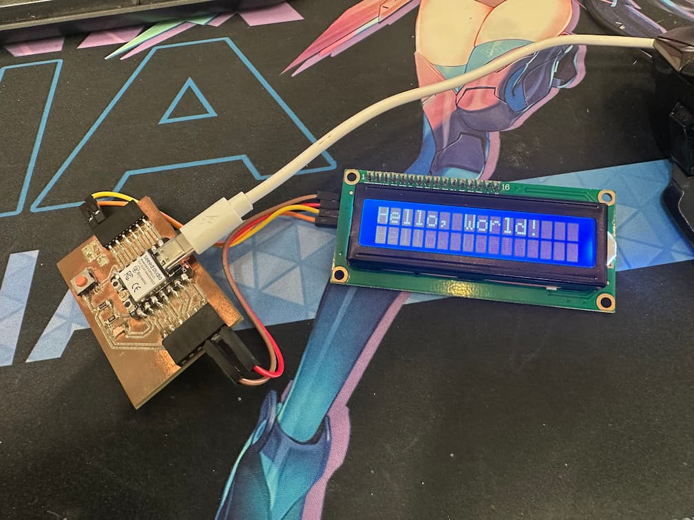
Before I upload the display program to the microcontroller. I also use the following program to test I2C reading for detect the I2C devices, and find the I2C address.
#include <Wire.h>

void setup() {
  Wire.begin();
  Serial.begin(115200);
  Serial.println("\nI2C Scanner");
}

void loop() {
  byte error, address;
  int nDevices;
  Serial.println("Scanning...");
  nDevices = 0;
  for(address = 1; address < 127; address++ ) {
    Wire.beginTransmission(address);
    error = Wire.endTransmission();
    if (error == 0) {
      Serial.print("I2C device found at address 0x");
      if (address<16) {
        Serial.print("0");
      }
      Serial.println(address,HEX);
      nDevices++;
    }
    else if (error==4) {
      Serial.print("Unknow error at address 0x");
      if (address<16) {
        Serial.print("0");
      }
      Serial.println(address,HEX);
    }
  }
  if (nDevices == 0) {
    Serial.println("No I2C devices found\n");
  }
  else {
    Serial.println("done\n");
  }
  delay(5000);
}
If a I2C device is connected to the microcontroller, a success message will be shown.
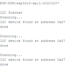
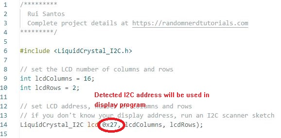
I can also find the I2C address is 0x27. It will be used in the display program.
If the device is not connected to microcontroller, it will display no I2C device.
Then, the display monitor can display the word what I programmed!
Display scrolling text
Scrolling text on the LCD is specially useful when I want to display messages longer than 16 characters. The library comes with built-in functions that allows you to scroll text.
- The function scrolls text on both rows. So, you can’t have a fixed row and a scrolling row;
- It doesn’t work properly if you try to display messages longer than 16 characters.
The following sketch displays a static message in the first row and a scrolling message longer than 16 characters in the second row.
#include <LiquidCrystal_I2C.h>

// set the LCD number of columns and rows
int lcdColumns = 16;
int lcdRows = 2;

// set LCD address, number of columns and rows
// if you don't know your display address, run an I2C scanner sketch
LiquidCrystal_I2C lcd(0x27, lcdColumns, lcdRows);

String messageStatic = "Static message";
String messageToScroll = "This is a scrolling message with more than 16 characters";

// Function to scroll text
// The function acepts the following arguments:
// row: row number where the text will be displayed
// message: message to scroll
// delayTime: delay between each character shifting
// lcdColumns: number of columns of your LCD
void scrollText(int row, String message, int delayTime, int lcdColumns) {
  for (int i=0; i < lcdColumns; i++) {
    message = " " + message;
  }
  message = message + " ";
  for (int pos = 0; pos < message.length(); pos++) {
    lcd.setCursor(0, row);
    lcd.print(message.substring(pos, pos + lcdColumns));
    delay(delayTime);
  }
}

void setup(){
  // initialize LCD
  lcd.init();
  // turn on LCD backlight
  lcd.backlight();
}

void loop(){
  // set cursor to first column, first row
  lcd.setCursor(0, 0);
  // print static message
  lcd.print(messageStatic);
  // print scrolling message
  scrollText(1, messageToScroll, 250, lcdColumns);
}
The scrolling text is done!!
28BYJ-48 Stepper Motor with ULN2003 Driver
The 28BYJ-48 is a 5-wire unipolar stepper motor that runs on 5V. It’s perfect for projects that require precise positioning, like opening and closing a vent.
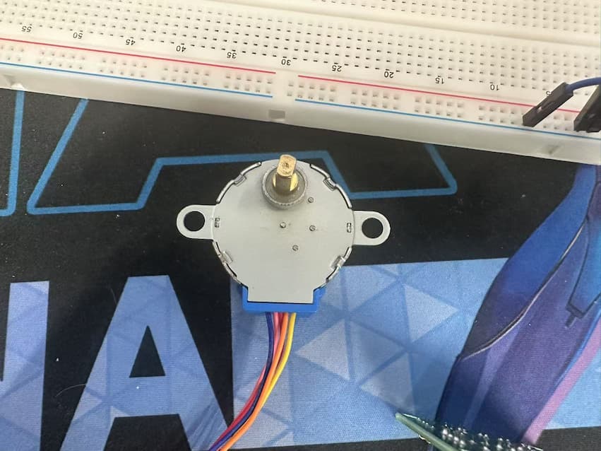
Pinout of 28BYJ-48 Stepper Motor
The 28BYJ-48 stepper motor has five wires.
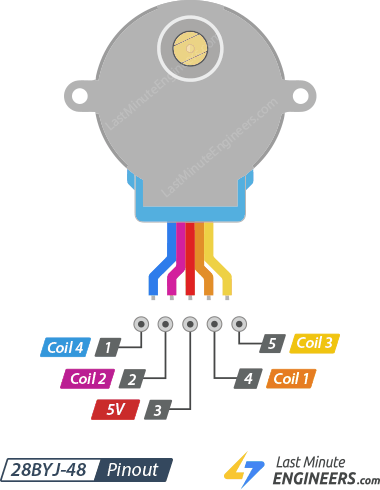
The 28BYJ-48 has two coils, each of which has a center tap. These two center taps are connected internally and brought out as the 5th wire (red wire).
Together, one end of the coil and the center tap form a Phase. Thus, 28BYJ-48 has a total of four phases.
The red wire is always pulled HIGH, so when the other lead is pulled LOW, the phase is energized.
The stepper motor rotates only when the phases are energized in a logical sequence known as a step sequence.
ULN2003 Driver Board
Because the 28BYJ-48 stepper motor consumes a significant amount of power, it cannot be controlled directly by a microcontroller such as Arduino. To control the motor, a driver IC such as the ULN2003 is required; therefore, this motor typically comes with a ULN2003-based driver board.
The ULN2003, known for its high current and high voltage capability, provides a higher current gain than a single transistor and allows a microcontroller’s low voltage low current output to drive a high current stepper motor.
The ULN2003 consists of an array of seven Darlington transistor pairs, each of which can drive a load of up to 500mA and 50V. This board utilizes four of the seven pairs.
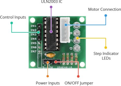
Pinout of the Driver Board
-
IN1 – IN4 are motor control input pins. Connect them to the ESP32C3’s digital output pins.
-
GND is the ground pin.
-
VCC pin powers the motor. Because the motor consumes a significant amount of power, it is preferable to use an external 5V power supply rather than from the ESP32C3.
The wire connection of stepper motor and ESP32C2 is shown as below.
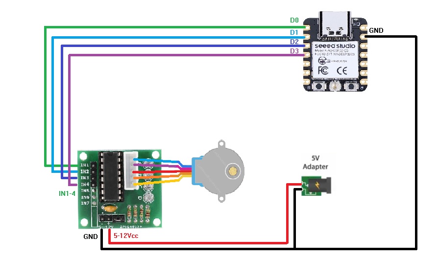
And I connect the circuit:
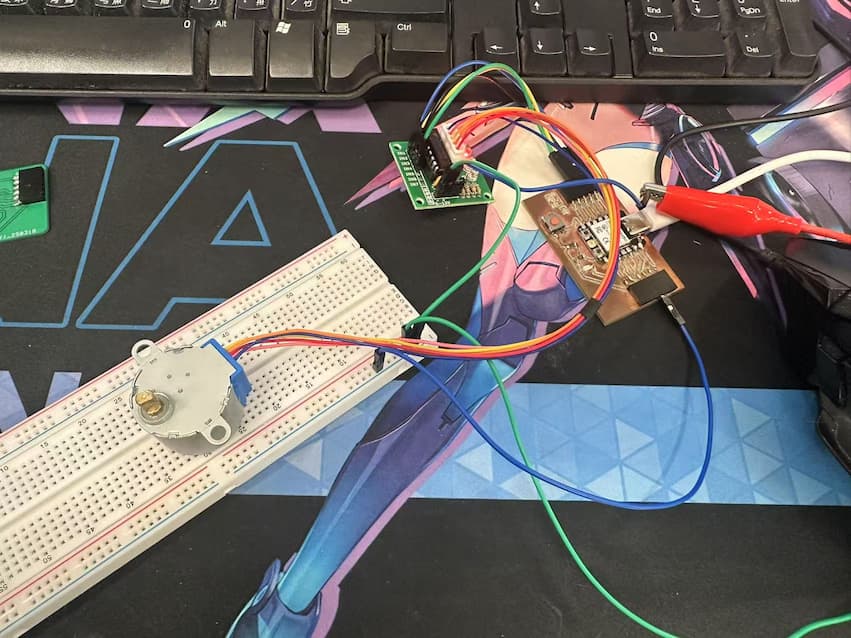
Here is a simple sketch that turns the motor slowly in one direction, then rapidly in the opposite direction.
//Includes the Arduino Stepper Library
#include <Stepper.h>

// Defines the number of steps per rotation
const int stepsPerRevolution = 2038;

// Creates an instance of stepper class
// Pins entered in sequence IN1-IN3-IN2-IN4 for proper step sequence
Stepper myStepper = Stepper(stepsPerRevolution, D0, D2, D1, D3);

void setup() {
    // Nothing to do (Stepper Library sets pins as outputs)
    Serial.begin(115200);
}

void loop() {
	// Rotate CW slowly at 10 RPM
	myStepper.setSpeed(10);
  Serial.println("CW");
	myStepper.step(stepsPerRevolution);
	delay(1000);

	// Rotate CCW quickly at 20 RPM
  myStepper.setSpeed(20);
  Serial.println("CCW");
	myStepper.step(-stepsPerRevolution);
	delay(1000);
}
I setup the stepper motor will spin 1 time with 10rpm speed in clockwise, and spin 1 time with 20rpm speed in counterclockwise.
I can control the direction of rotation through modify the variable stepsPerRevolution as positive(Clockwise) or negative(CounterClockwise). And set the rotation speed through the function myStepper.setSpeed().
Then, it works.