Week 16. System Integration
Chipping away at the final steps to make the Tactile Labyrinth.
Hand scale test print
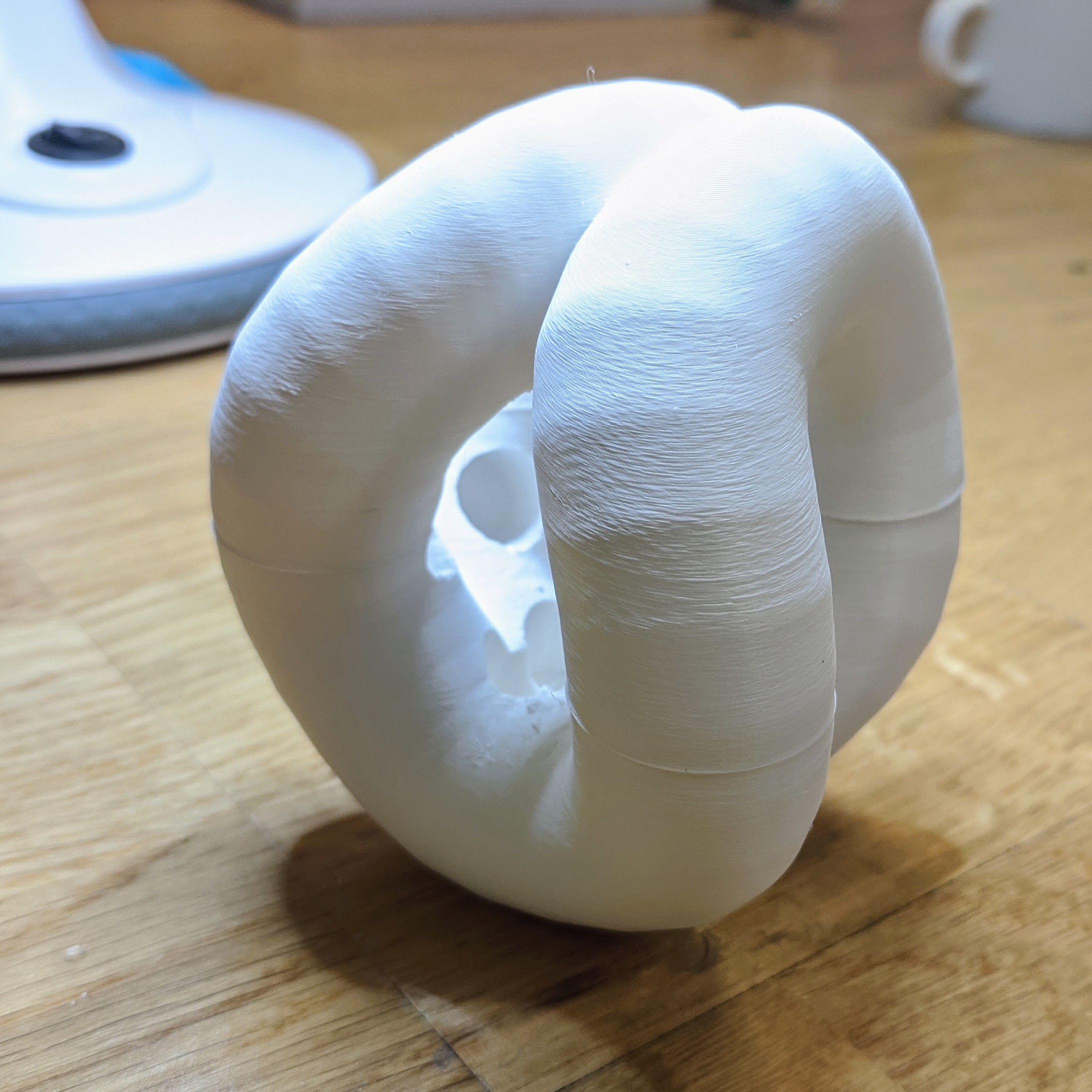
I wanted to hold a version of the design made with the web app.
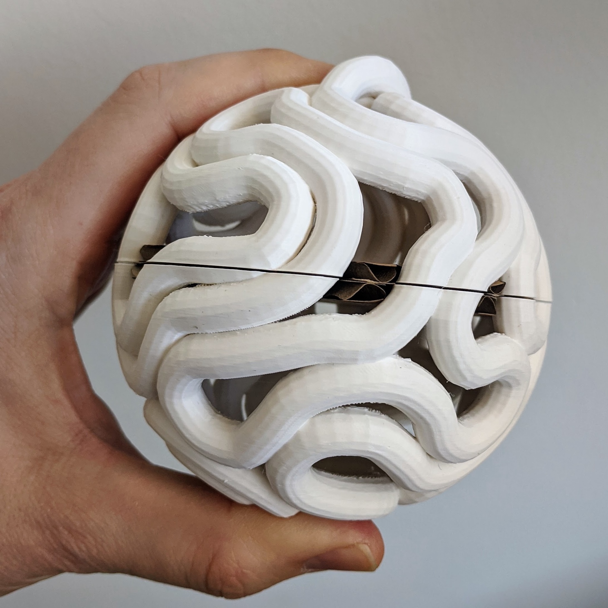
Prusa Mini, 24 hour print, generic white PLA.
One idea is that this will become the "nucleus" of the soft version of the pixel ball. Electronics and battery.
Another idea is to scale this so that LEDs can be embedded on the inside.
Design with positive and negative space
The mesh that my design app outputs has overlapping shapes where the ropes rest against each other. Prusa slicer doesn't have a problem with this. It makes the perimeter and infill as if the shape is unioned. But trying to do any other Boolean modelling on the shape in Blender or JS made a lot of broken and sad meshes.
I found a workaround: export positive and negative space as 2 separate STL files, then combine them with Prusa Slicer.
- Rope simulation and mesh generation works as before.
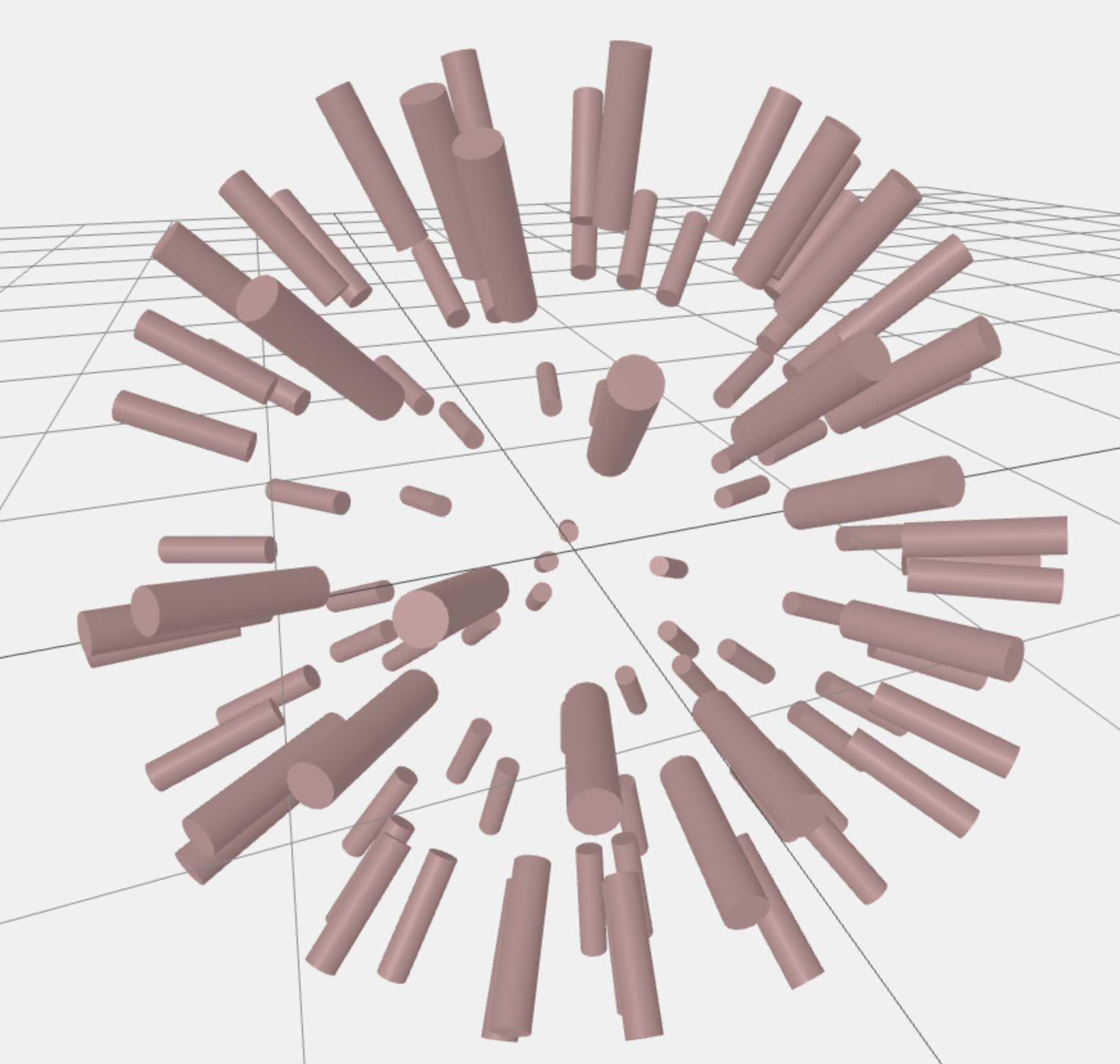
- LED positions and rotations calculated and previewed.
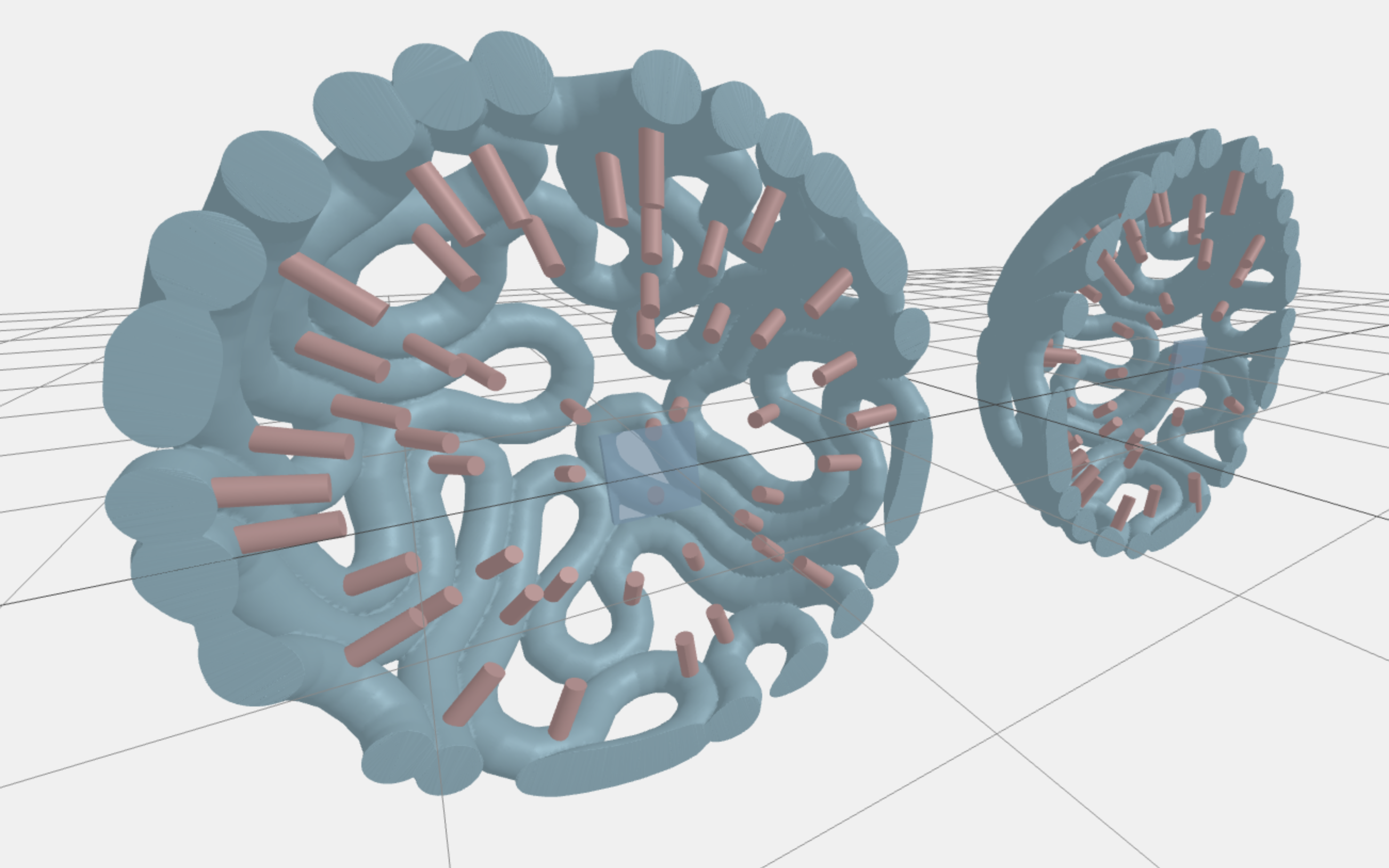
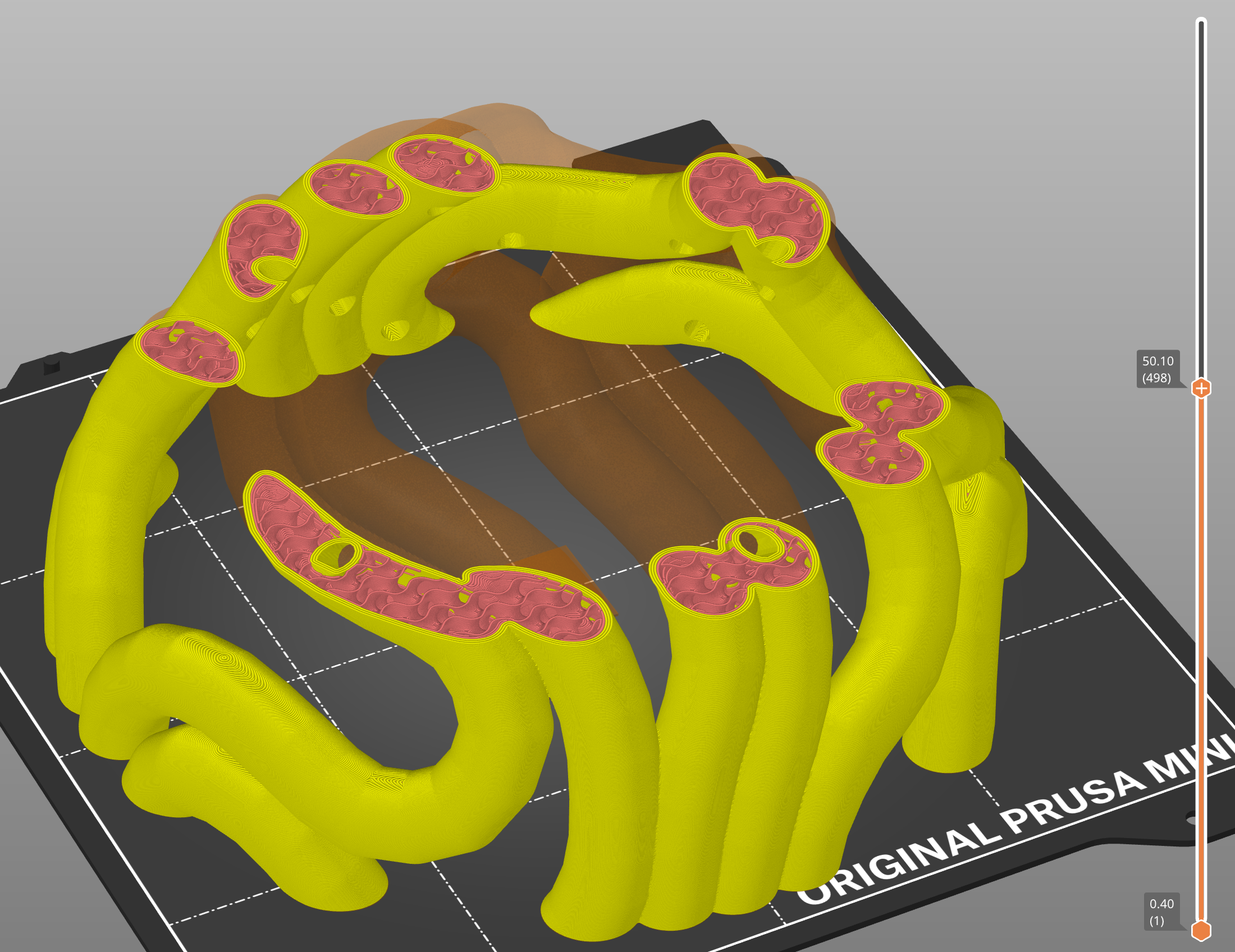
- Slice the rope mesh and preview the LED positions with it. Export positive and negative STLs.
(Possible enhancement is to do this all with SDF modeling.)
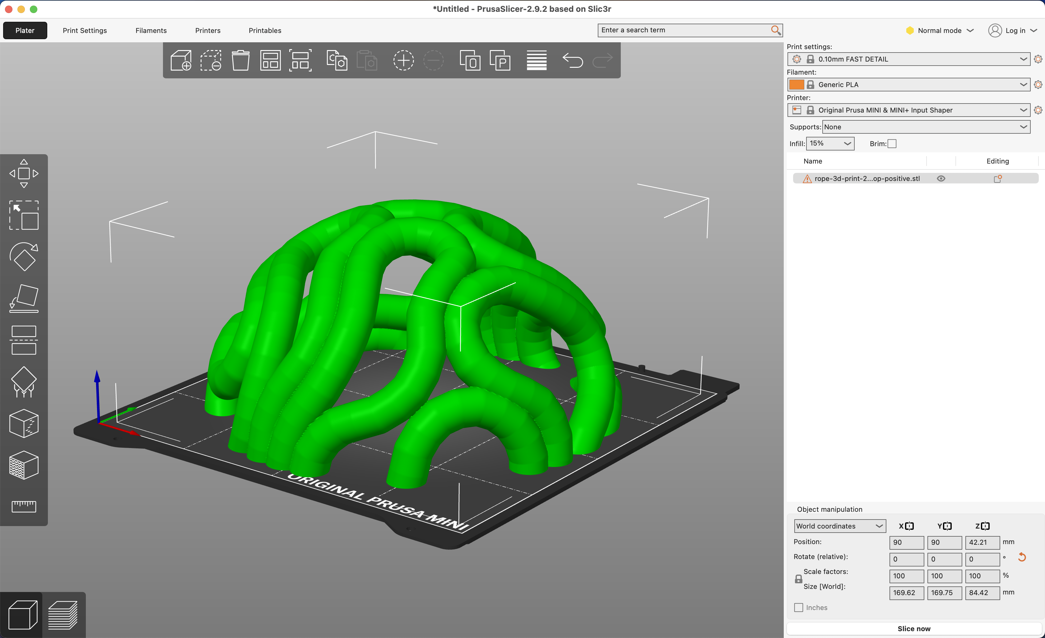
- Load the positive STL in Prusa Slicer.
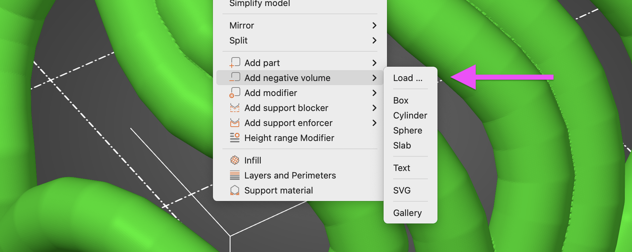
- Right click the positive and choose Add negative volume > Load… to subtract the negative STL from the positive.
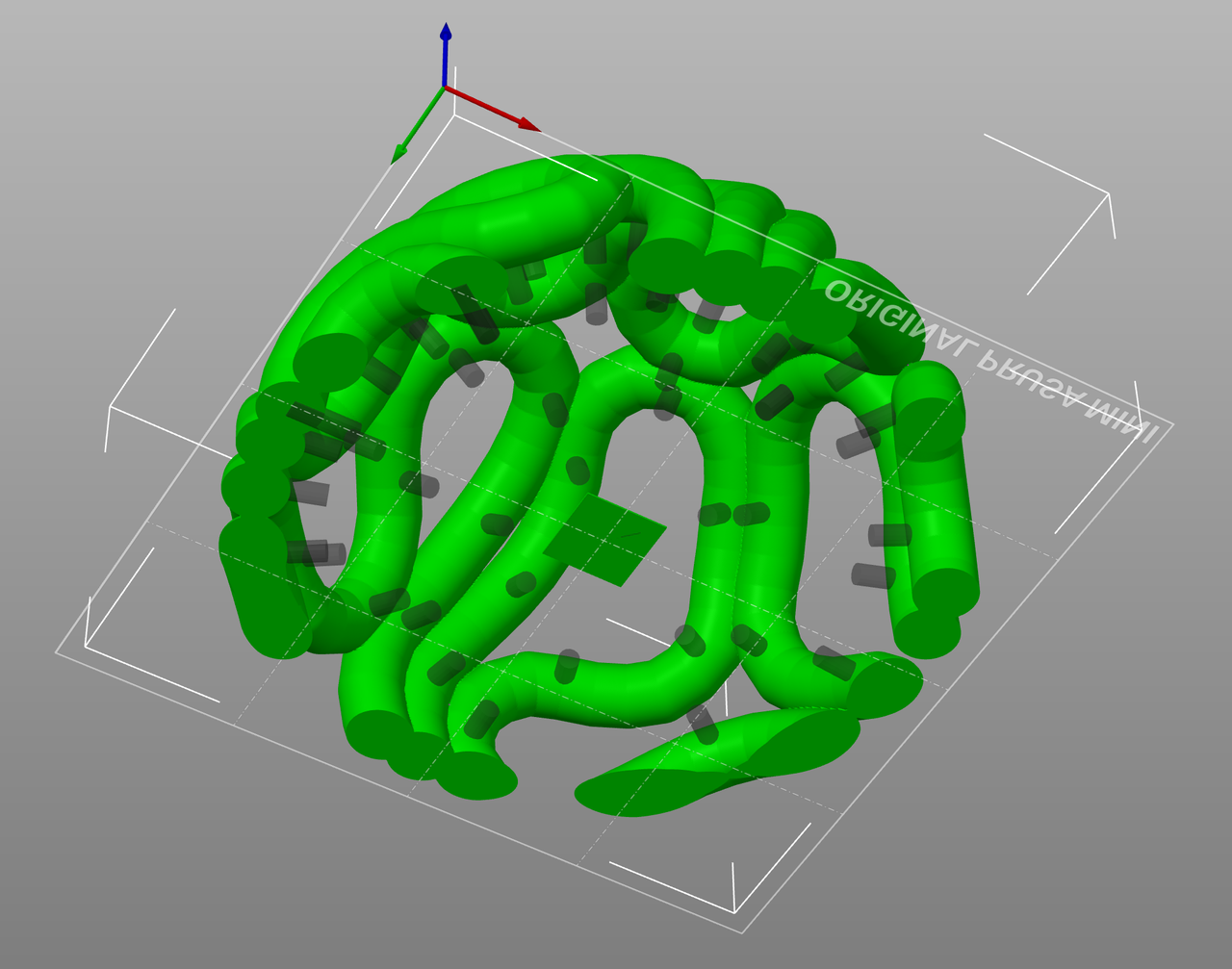
The rectangle in the both positive and negative STLs is for registration. They import with the correct orientation relative to each other, as they are saved. When they are lined up correctly, the registration tabs negate each other.
Click "Enter 3D Print Mode" on the rope simulation web app to try the new LED socket parameters and multiple STL generation.
Test print
Smaller test print, with the sockets scaled for some bigger LEDs that I wanted test.
The white filament absorbs more if the light than I hoped. I need to experiment with clear filament.
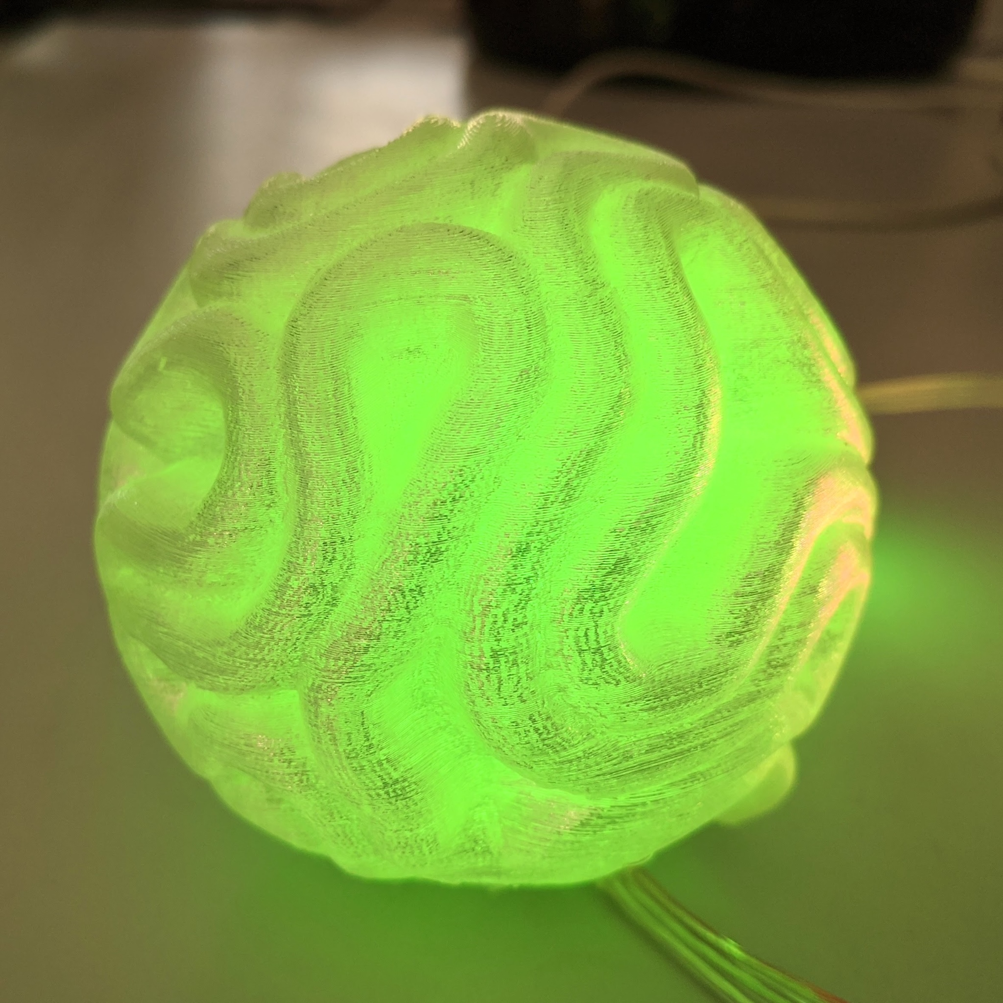
Transparent PLA test
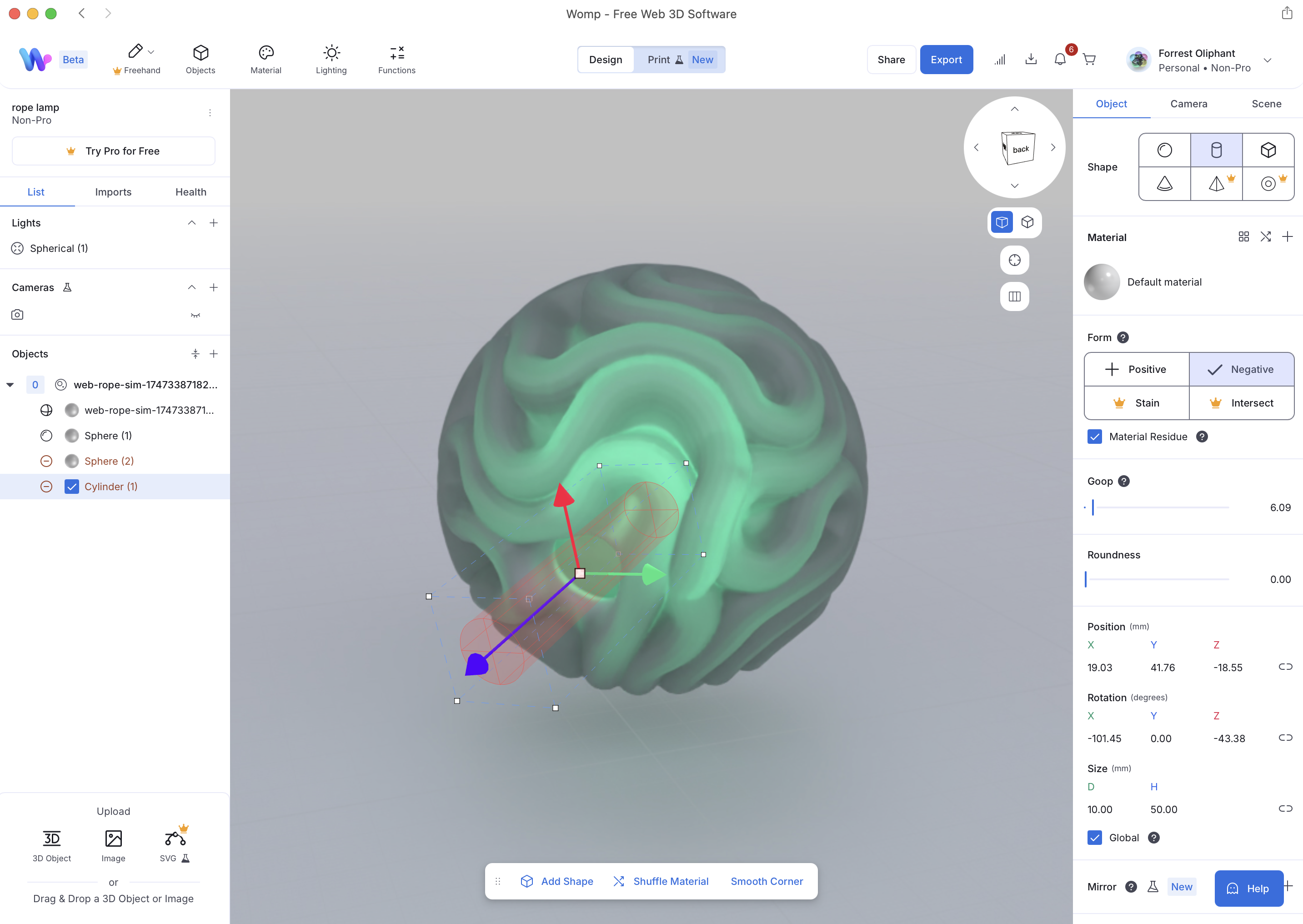
I have been experimenting with Womp again. It's not parametric CAD, but there are some nice features for quick 3D modeling with Booleans.
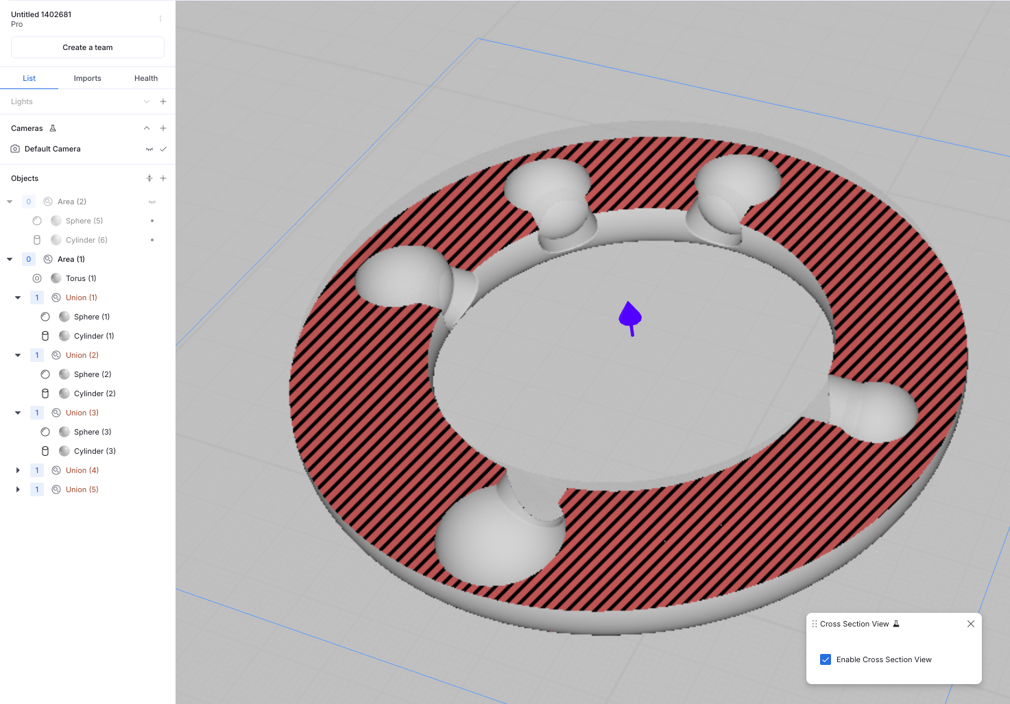
Womp's cross-section view mode, where you can move the plane to preview the cross-section of the model.
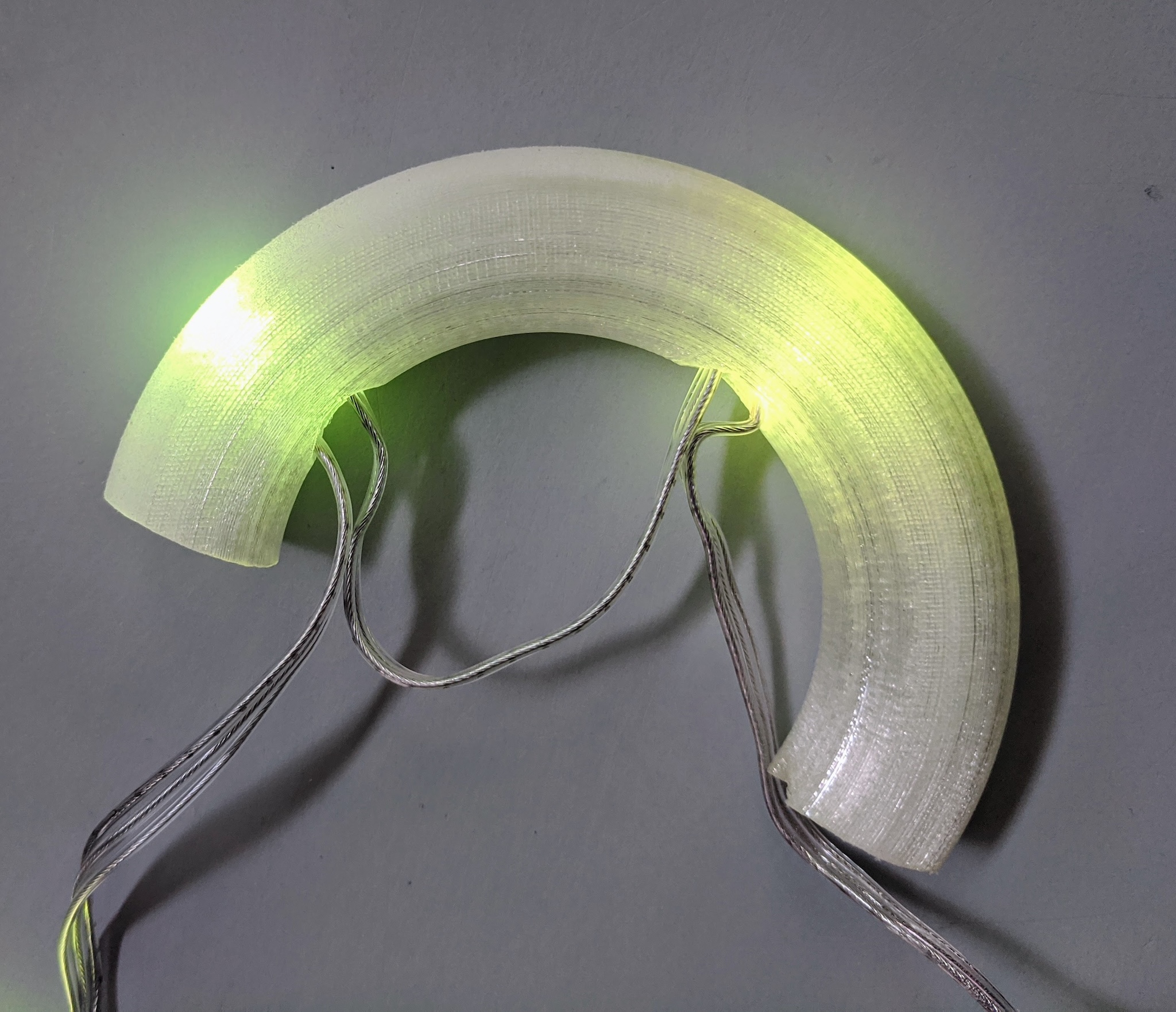
Transparent PLA, 1mm outer shell, 20% infill with gyroid pattern, Ultimaker S3.
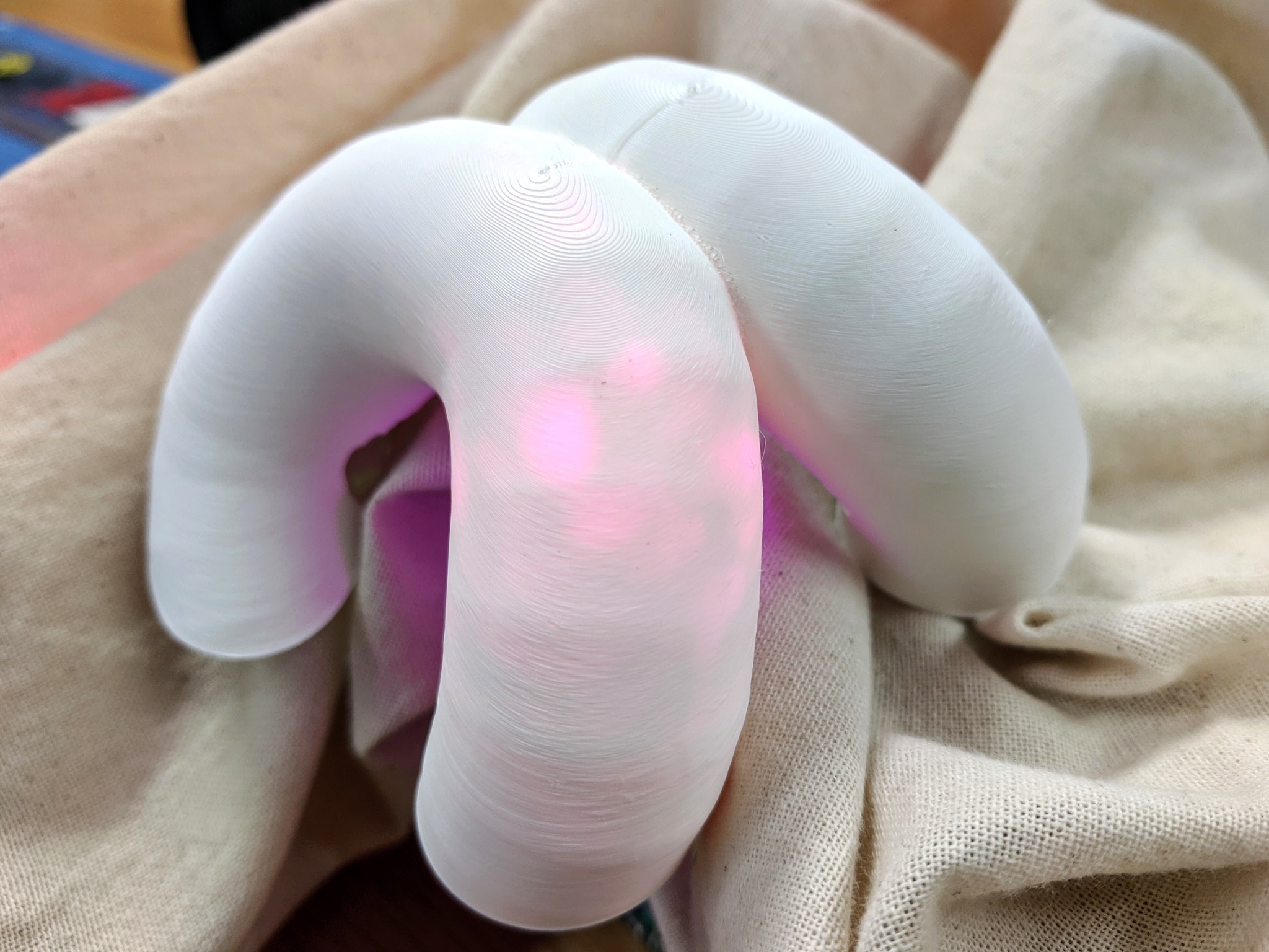
The socket design works. The pre-wired LEDs can bend to about 12.6mm, so that will be a base parameter for the final model. For light diffusion, I think it's good to keep some space for infill between the socket and the outer edge.
This test print is designed with LED sockets of varying sizes and spacings to see if the premade LED wire can fit. I'll print it with transparent PLA to test how the light looks from the outside.
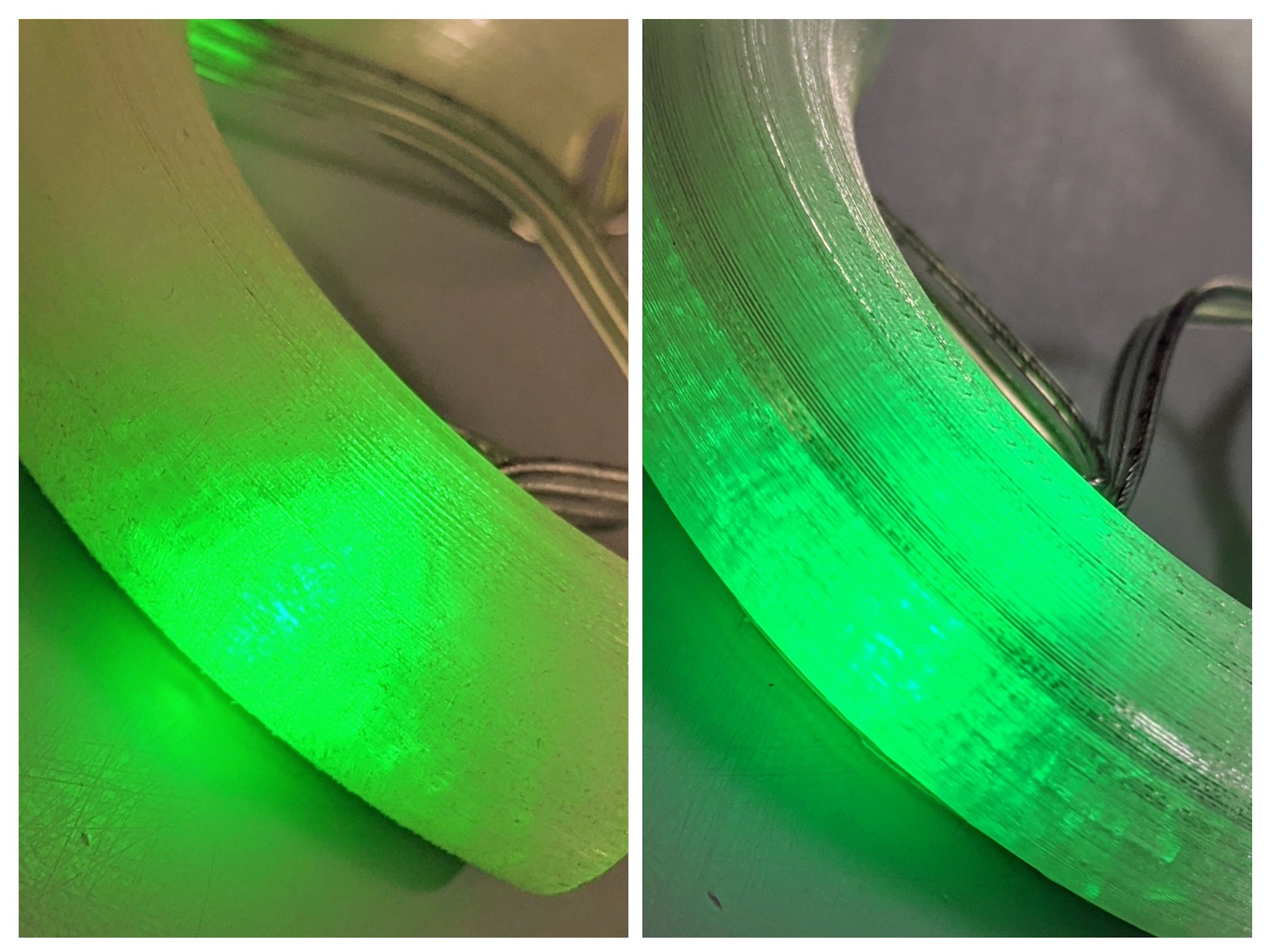
Sanded on left and raw on the right. Unsanded feels nicer, and the sanding doesn't enhance the light diffusion enough to be worth it.
Test print as small lamp
Building on the version that I milled in week 17, I subtracted a cavity to make a small lamp.
Future nightlight.
Integration
With material and LED mounting questions answered, it's time to go on to the rest of the integration plan.
Plan A
Plan B
If I talk myself out of embedding the LEDs on the inside of the ball, and thinking that I'll go back to the soft design. I can still use the generated 3d print as the internal case for the electronics.
Plan C
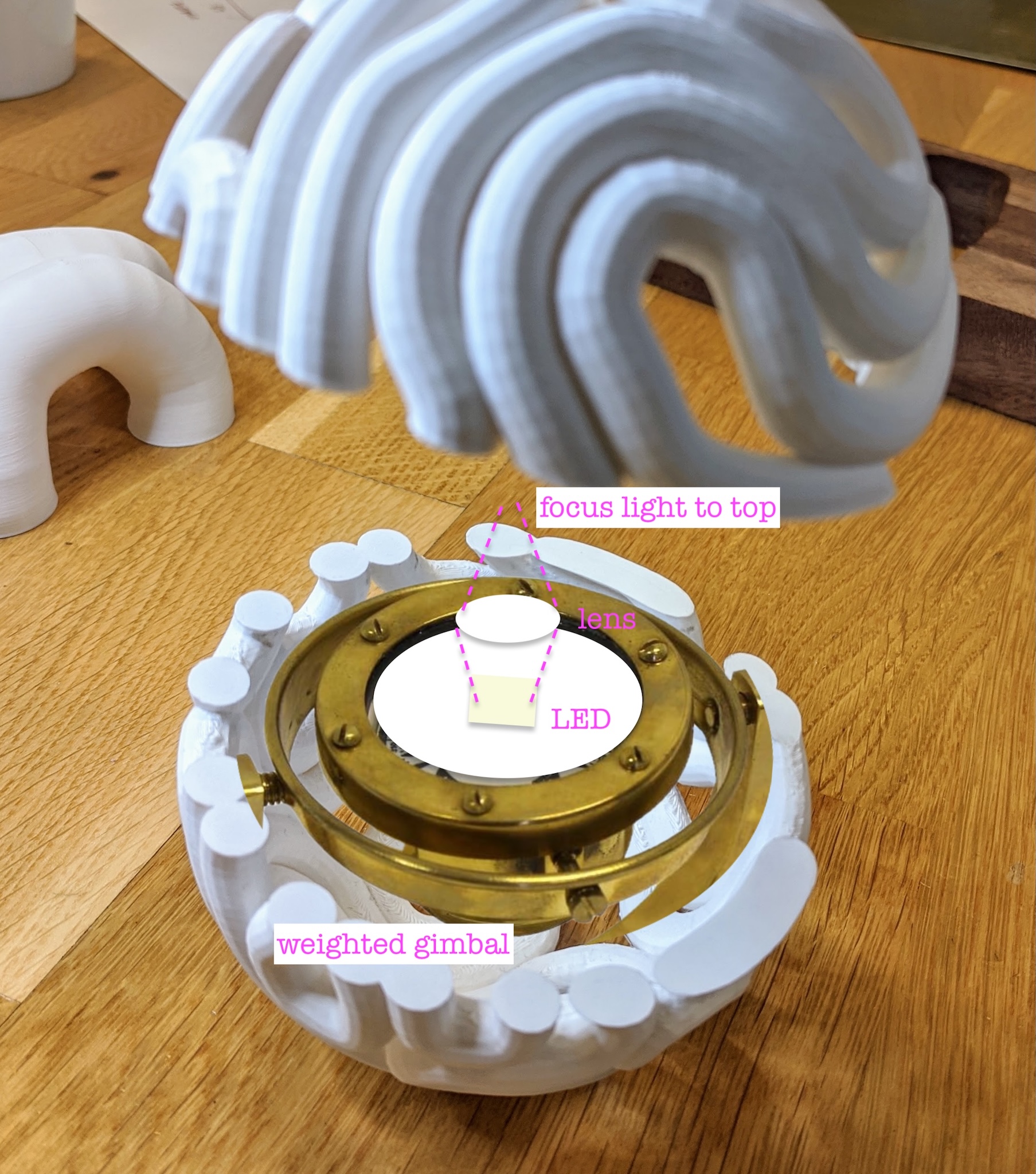
A gimbal like this for the middle of the softball-sized labyrinth ball. Instead of compass, a single focused LED shining up ▲ with battery down ▼ for weight. It will always shine up, so you could manually make the light follow the path. Throw out the microcontroller and LED strips. Done.