Week 15. Interface and Application Programming
Building an interface for calibrating a ball of addressable LEDs.

💡 Note that this "readme driven development" development strategy fits well with "document as you go." By having this markdown file as well as the html, js, and ino files in the LLM context, it becomes easier to debug issues across these boundaries. Then it is one step to commit and publish changes.
Intro
During week 13 I iterated on two methods for mapping positions of an LED string around a ball. The first version used a math function to estimate the positions of the LEDs. The second version involved making a list of key positions, moving a white pixel around until the index was close to the estimated position, and then having the code interpolating the LED positions between those mapped indexes. This involved more manual work, and ended up being more accurate, but still ended up with some funky pixels.
As I was working through these versions, I had the ball stationary on the desk, and I moved the accelerometer independently to test the calibration. Only once I had a mapping that seemed correct did I integrate the cardboard prototype.
Once I had the wireless version in my hands with the central accelerometer, and through a conversation with Kris, I thought of a new way to do the calibration process.
For every pixel, or every nth pixel:
- Send a serial message with the LED index.
- Blink red for 3 seconds.
- The person moves the ball until that pixel is on top.
- Shine green for 1 second.
- The accelerometer value (which is the ball's orientation) is then stored for that pixel.
- Once the whole LED string is calibrated, a list is sent via serial message, that can be hardcoded into the positioning library and used in other Arduino programs for the ball.
This calibration program will be more flexible than the previous versions, and will be better suited for the organic simulated shapes that I hope will be the final form. Redesigning the LED path, or accelerometer position, will require another calibration pass. But I think it will be easier and more enjoyable than my past versions. This will let me iterate on the design.
Spec
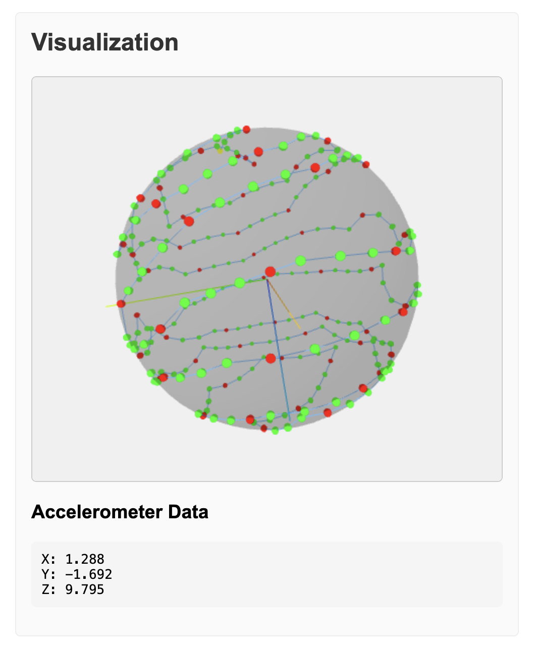
A web app will listen to the serial messages via WebSerial, as in week 12's machine interface. The accelerometer's orientation will be visualized, and each LED position as it is mapped. The webapp will be able to query the device for any existing mapping, and be able to skip to any index.
Previous code
For reference. Don't change these files.
This version
Initial prompt
Without writing code, help me fill out subsections of this markdown spec. We have a working version, but want to redesign the calibration flow entirely. We also want to make a web visualization to make the process more interactive. Once all of the sections are filled out, we will have enough of a spec to start implementing.
Conclusion
- readme.md: the whole readme initialized and edited through the development process.
- index.html: the calibration app
Building on my short experience with "readme driven development" I can see that this development flow is allowing me take on larger chunks of work. This app and documentation took 5 hours.
My modus operandi with maker projects in the past has been to relentlessly simplifiy. Does it really need to be wireless? Let's make it easier by just using a wire. Does it really need a microcontroller? Let's just wire the buttons to the output directly.
I still think simplification is a valuable maker skill, but now when the concept does demand a certain level of complexity, I'm feeling more ready to take on the challenge.
- ← Previous
Week 14. Molding and Casting - Next →
Week 16. System Integration