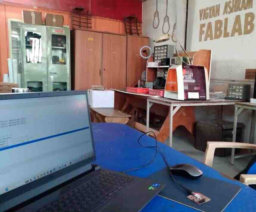
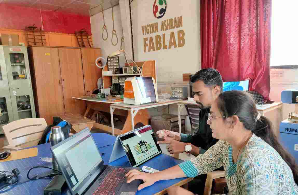
Embedded Programming
This week is dedicated to Embedded Programming, focusing on understanding the datasheet of microcontrollers, programmes, different programming languages like C++, Python. Working envirnoment like Ardino ide, Visual code, also compare the performance and development workflows for other architectures.We used XIAO RP2040 board, which is from Raspberry Pi family of microcontrollers. All about architecture and all of this week's learning in the assignment.
Objectives :
- Understanding the data sheets of microcontrollers- Compare the performance and development workflows for other architectures
1. What is Datasheet?
A datasheet serves as a comprehensive guide for electronic components, detailing their functions and usage instructions. Typically authored by engineers, these documents can sometimes present challenges in readability due to their technical nature.
A datasheet usually has several sections, and the first page is like a quick snapshot of what the part does and what it can do for you. It includes a description of the part's purpose, its main features, and basic specs. Sometimes, you'll also see a diagram showing how the part works inside. This first page helps you decide if the part might be a good fit for your project.
A pinout tells you what each pin on a part does and where it's located. It's important to know where pin 1 is, marked specially on the part, so you plug it in correctly. The pins are numbered counterclockwise. You might see acronyms like VCC for supply voltage, CLK for clock, CLR for clear, and OE for output enable. These are usually explained later in the datasheet, but you can also search them on Google or Wikipedia. If a pin has a star or a line over its name, it means it's active low, so you activate it by pulling it to 0V instead of VCC.To read more about Please refer this site Click here
XIAO RP2040 Development Board
In previous week we production week and we used XIAO RP2040 development board.Now in Embedded Programming we are going to explore about the datasheet for XIAO RP2040 and done embedded Programme for this board. First we studied about the xiao family.
About Xiao
XIAO is a versatile series of development boards featuring a compact design and powerful processors. With its thumb-sized form factor and rich peripherals, XIAO serves as a complete microcontroller, simplifying the process of designing complex electronic systems by providing a pre-integrated and tested platform. This allows developers to focus on creating unique features and functions without the hassle of integrating and testing individual components. The XIAO series finds applications across various verticals including mechanical keyboards, trackers, detection tools, wearable devices, and healthcare devices. Each XIAO module, such as XIAO SAMD21, XIAO RP2040, XIAO nRF52840, XIAO nRF52840 Sense, and XIAO ESP32C3, offers specific features catering to different needs. The user manual provides comprehensive guidance from module selection to final manufacturing, making it easy for developers to incorporate XIAO into their designs. Whether it's for musical gadgets, mechanical keyboards, environmental data collection, or AIoT projects, XIAO offers a range of options to suit diverse application requirements.
| Name | Description | Recommended Application |
|---|---|---|
| XIAO SAMD21 | A universal mini dev board with strong stability and compatibility | Controller for 3D Printers, Trackers, Musical gadgets, Mechanical Keyboards |
| XIAO RP2040 | Compatible with the Raspberry Pi RP2040 ecosystem | Environmental data collection, Detection tools |
| XIAO nRF52840 | Mini low-power consumption dev board supporting Bluetooth 5.0 | Smart home devices, TinyML and AIoT projects |
| XIAO nRF52840 Sense | Advanced version of XIAO nRF52840 with onboard microphone and 3-axis IMU | Smart home devices, AIoT projects |
| XIAO ESP32C3 | Budget-friendly and high-performance RISC-V WiFi&BLE dev board | Smart home devices, AIoT projects |
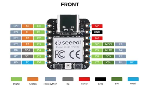
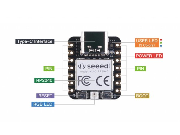
Seeed Studio XIAO RP2040
Digital pins: Think of these as the on/off switches of our microcontroller. we can use them to control things like LEDs, sensors, or motors.
Analog pins: These are like sensors that can measure varying levels of voltage. Useful for reading values from things like temperature sensors or light sensors.
PWM pins: PWM stands for Pulse Width Modulation. These pins can simulate analog output by rapidly turning on and off, allowing you to control things like the brightness of an LED or the speed of a motor.
I2C interface: This is a way for different electronic components to communicate with each other. It's like a digital conversation between devices.
UART interface: UART stands for Universal Asynchronous Receiver/Transmitter. It's a way for our microcontroller to communicate with other devices, like our computer or another microcontroller.
SPI interface: SPI stands for Serial Peripheral Interface. It's another way for devices to communicate with each other, often used for connecting peripherals like displays or SD cards.
SWD bonding pad interface: This is a specialized interface used for debugging and programming the microcontroller. It's like a special connection that helps you upload code and troubleshoot problems.
So, we have a microcontroller with these specs, we have a versatile tool for building all sorts of electronic projects!
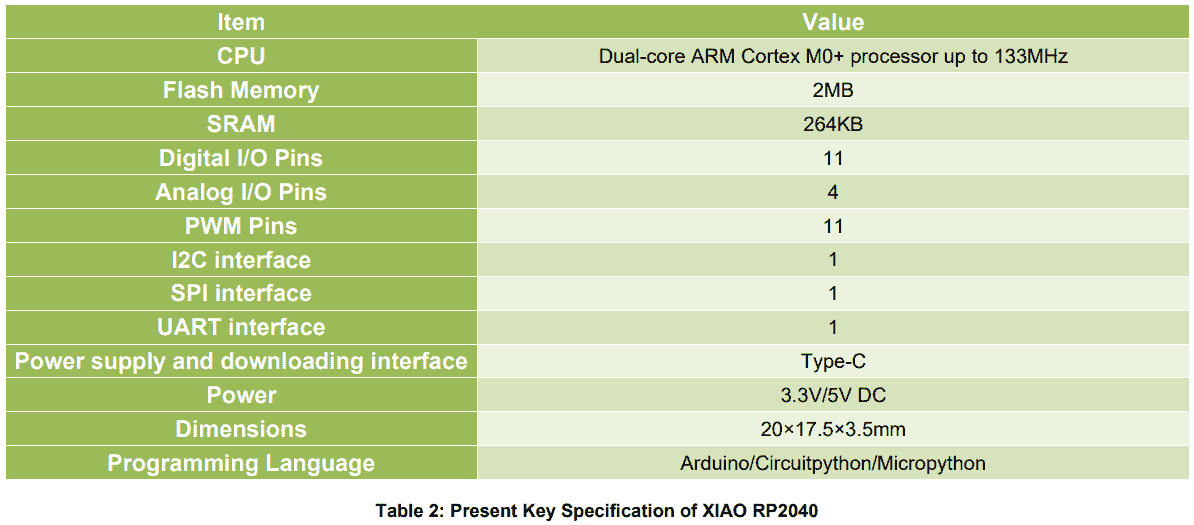
Specification of XIAO RP2040
Chip datasheet for XIAO RP2040
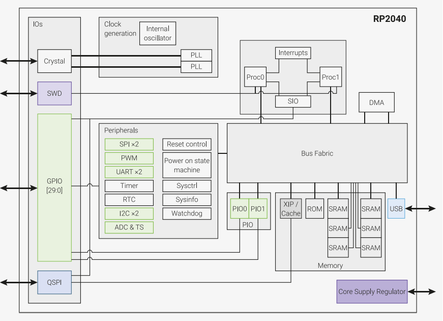
Microcontrollers connect the world of software to the world of hardware. They allow developers to write software which interacts with the physical world in the same deterministic, cycle-accurate manner as digital logic. They occupy the bottom left corner of the price/performance space, outselling their more powerful brethren by a factor of ten to one. They are the workhorses that power the digital transformation of our world. RP2040 is the debut microcontroller from Raspberry Pi. It brings our signature values of high performance, low cost, and ease of use to the microcontroller space. With a large on-chip memory, symmetric dual-core processor complex, deterministic bus fabric, and rich peripheral set augmented with our unique Programmable I/O (PIO) subsystem, it provides professional users with unrivalled power and flexibility. With detailed documentation, a polished MicroPython port, and a UF2 bootloader in ROM, it has the lowest possible barrier to entry for beginner and hobbyist users. RP2040 is a stateless device, with support for cached execute-in-place from external QSPI memory. This design decision allows you to choose the appropriate density of non-volatile storage for your application, and to benefit from the low pricing of commodity Flash parts. RP2040 is manufactured on a modern 40nm process node, delivering high performance, low dynamic power consumption, and low leakage, with a variety of low-power modes to support extended-duration operation on battery power.
RP2040 Microcontroller Information
| Feature | Description |
|---|---|
| Dual ARM Cortex-M0+ @ 133MHz | Two ARM Cortex-M0+ processors running at 133MHz. |
| On-chip SRAM | 264kB on-chip SRAM in six independent banks. |
| Off-chip Flash Memory | Support for up to 16MB of off-chip Flash memory via dedicated QSPI bus. |
| DMA Controller | Direct Memory Access controller for efficient data transfer. |
| AHB Crossbar | Fully-connected AHB crossbar for efficient data routing. |
| GPIO Pins | 30 GPIO pins, 4 of which can be used as analogue inputs. |
| Peripherals |
|
| PLLs | 2 on-chip PLLs to generate USB and core clocks. |
| Other Features |
|
Whatever your microcontroller application, from machine learning to motor control, from agriculture to audio, RP2040 has the performance, feature set, and support to make your product fly.
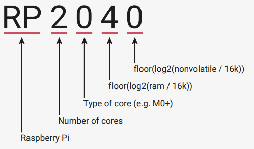
Why is the chip called RP2040?
The post-fix numeral on RP2040 comes from the following,
1. Number of processor cores (2)
2. Loosely which type of processor (M0+)
3. floor(log2(ram / 16k))
4. floor(log2(nonvolatile / 16k)) or 0 if no onboard nonvolatile storage
RP2040 Microcontroller Features
| Feature | Description |
|---|---|
| Dual Cortex M0+ processor cores | Up to 133MHz |
| Embedded SRAM | 264kB in 6 banks |
| GPIO | 30 multifunction GPIO |
| SPI Flash | 6 dedicated IO supporting XIP |
| Dedicated hardware | For commonly used peripherals |
| Programmable IO | For extended peripheral support |
| ADC | 4 channel ADC with internal temperature sensor, 500ksps, 12-bit conversion |
| USB | USB 1.1 Host/Device |
Execution from External Memory:
The chip can run code directly from external memory using specific interfaces like SPI, DSPI, or QSPI, which are types of communication protocols.
Cache for Performance:
There's a small cache onboard that helps speed up operations for common tasks.
Debugging via SWD:
You can debug the chip using the Serial Wire Debug (SWD) interface.
Internal SRAM:
The chip has internal SRAM (Static Random Access Memory) that can hold both code and data. It's divided into 6 banks to allow multiple accesses at the same time.
DMA Bus Masters:
These are controllers that help offload repetitive data transfer tasks from the main processor, improving efficiency.
GPIO Pins:
General Purpose Input/Output pins can be controlled directly or through various dedicated logic functions.
Dedicated Hardware:
The chip has built-in hardware for commonly used communication protocols like SPI, I2C, and UART.
PIO Controllers:
Programmable Input/Output controllers can be configured to perform various IO functions as needed.
USB Controller:
There's a USB controller onboard with an embedded PHY (Physical Layer) that can be configured to act as either a Full-Speed (FS) or Low-Speed (LS) Host or Device, controlled by software.
ADC Inputs:
Analog-to-Digital Converter inputs allow the chip to measure analog signals. These inputs are shared with GPIO pins.
PLLs:
Phase-Locked Loops are used to generate stable clock signals. The chip has two PLLs: one for providing a fixed 48MHz clock for USB or ADC operations, and another for a flexible system clock that can go up to 133MHz.
Internal Voltage Regulator:
There's a built-in voltage regulator that supplies power to the core components of the chip, reducing the need for external voltage regulation.
Overall, these features enable the chip to handle a wide range of tasks efficiently and with flexibility.
Pinout Reference
This part gives us a simple guide to which pins do what. If you need more detailed info, like how much electricity they handle or what the package looks like.Read More
Pin Locations for RP2040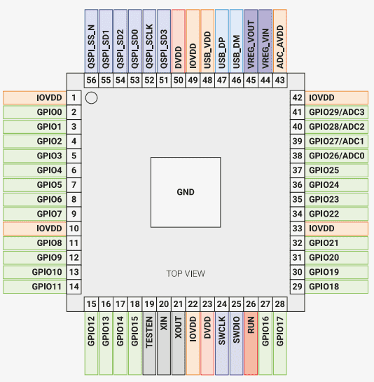
Pin Descriptions
| Name | Description |
|---|---|
| GPIOx | General-purpose digital input and output. RP2040 can connect one of a number of internal peripherals to each GPIO, or control GPIOs directly from software. |
| GPIOx/ADCy | General-purpose digital input and output, with analogue-to-digital converter function. The RP2040 ADC has an analogue multiplexer which can select any one of these pins, and sample the voltage. |
| QSPIx | Interface to a SPI, Dual-SPI or Quad-SPI flash device, with execute-in-place support. These pins can also be used as software-controlled GPIOs, if they are not required for flash access. |
| USB_DM and USB_DP | USB controller, supporting Full Speed device and Full/Low Speed host. A 27Ω series termination resistor is required on each pin, but bus pull-ups and pull-downs are provided internally. |
| XIN and XOUT | Connect a crystal to RP2040’s crystal oscillator. XIN can also be used as a single-ended CMOS clock input, with XOUT disconnected. The USB bootloader requires a 12MHz crystal or 12MHz clock input. For recommended crystals, see Crystal Oscillator (Section 2.16). |
| RUN | Global asynchronous reset pin. Reset when driven low, run when driven high. If no external reset is required, this pin can be tied directly to IOVDD. |
| SWCLK and SWDIO | Access to the internal Serial Wire Debug multi-drop bus. Provides debug access to both processors, and can be used to download code. |
| TESTEN | Factory test mode pin. Tie to GND. |
| GND | Single external ground connection, bonded to a number of internal ground pads on the RP2040 die. |
| IOVDD | Power supply for digital GPIOs, nominal voltage 1.8V to 3.3V |
| USB_VDD | Power supply for internal USB Full Speed PHY, nominal voltage 3.3V |
| ADC_AVDD | Power supply for analogue-to-digital converter, nominal voltage 3.3V |
| VREG_VIN | Power input for the internal core voltage regulator, nominal voltage 1.8V to 3.3V |
| VREG_VOUT | Power output for the internal core voltage regulator, nominal voltage 1.1V, 100mA max current |
| DVDD | Digital core power supply, nominal voltage 1.1V. Can be connected to VREG_VOUT, or to some other board-level power supply |
GPIO Functions
Each GPIO (General Purpose Input/Output) pin on a device can be linked to an internal part of the device using the GPIO functions listed below. Some internal connections can be found in multiple spots, which offers flexibility at the system level. SIO, PIO0, and PIO1 can link to all GPIO pins and are managed by software , allowing them to serve various functions.
Function Descriptions
| Function Name | Description |
|---|---|
| SPIx | Connect one of the internal PL022 SPI peripherals to GPIO |
| UARTx | Connect one of the internal PL011 UART peripherals to GPIO |
| I2Cx | Connect one of the internal DW I2C peripherals to GPIO |
| PWMx A/B | Connect a PWM slice to GPIO. There are eight PWM slices, each with two output channels (A/B). The B pin can also be used as an input, for frequency and duty cycle measurement. |
| SIO | Software control of GPIO, from the single-cycle IO (SIO) block. The SIO function (F5) must be selected for the processors to drive a GPIO, but the input is always connected, so software can check the state of GPIOs at any time. |
| PIOx | Connect one of the programmable IO blocks (PIO) to GPIO. PIO can implement a wide variety of interfaces, and has its own internal pin mapping hardware, allowing flexible placement of digital interfaces on bank 0 GPIOs. The PIO function (F6, F7) must be selected for PIO to drive a GPIO, but the input is always connected, so the PIOs can always see the state of all pins. |
| CLOCK GPINx | General purpose clock inputs. Can be routed to a number of internal clock domains on RP2040, e.g. to provide a 1Hz clock for the RTC, or can be connected to an internal frequency counter. |
| CLOCK GPOUTx | General purpose clock outputs. Can drive a number of internal clocks (including PLL outputs) onto GPIOs, with optional integer divide. |
| USB OVCUR DET/VBUS | USB power control signals to/from the internal USB controller |
| DET/VBUS EN | USB power control signals to/from the internal USB controller |
2. Comparison of Microcontrollers
| Parameters | Raspberry Pi Pico | Arduino Uno | ESP 32 | ESP8266 |
|---|---|---|---|---|
| Microcontroller | RP2040 | ATMega328P | ESP32 | ESP8266 |
| Core | Dual core | Single core | Dual core | Single core |
| Architecture | 32 bit ARM cortex M0+ | 8 bit RISC | 32 bit LX6 with 600 DMIPS | 32 bit LX106 |
| Clock Speed | Up to 133MHz | 16 MHz | Up to 240MHz | Up to 160MHz |
| Operating voltage | 3.3v | 5v | 3.3v | 3.3v |
| GPIO Voltage | 3.3v | 5v | 3.3v | 3.3v |
| Digital pins | 26 | 14 | 36 | 16 |
| PWM pins | 16 | 6 | 32 | 16 |
| Analog pins | 3 | 6 | 15 | 1 |
| SPI/I2C/UART/I2s | 2/2/2 | 1/1/1 | 4/2/2/2 | 2/1/2/2 |
| Wifi | NO | NO | YES | YES |
| Bluetooth | NO | NO | YES | NO |
| Built-in sensor | Temperature sensor | NO | Touch, Temperature, Hall Effect sensors | NO |
| Programming Language | C/C++, Micro Python | Arduino IDE, C/C++ | Arduino IDE, C/C++, Micro Python | Arduino IDE, C/C++, Micro Python, Javascript |
| On board Programming LED | GP25 pin | D13 pin | D2 pin | D0 pin |
| Flash | 2MB | 32KB | 4MB | 4MB |
| RAM | 264KB | 264KB | 520KB | 128KB |
| EEPROM | NO | 1KB | NO | 520B |
| Advantages | Best for Machine Learning | Best for beginners and Pro because there are so many modules and library. | Best for IoT projects | Best for IoT projects |
Keylearnings:
So,In this week assignment we discussed and understand about datasheet.how to read and understand specifications of our datasheet. For our microcontroller, we used Raspberry Pi Pico RP2040 Microcontroller.It works on 32 bit ARM cortex M0+n Architechture. It is Dual core, Operating voltage 3.3v, GPIO Voltage 3.3v, Digital pins 26,Built-in sensor Temperature sensor,RAM 264KB as in above explained.It is Best for Machine Learning and we can pragramme in C/C++, Micro Python languages with this microcontroller.
Then we compared our selected microcontroller with other by which we able to understand about other microcontrollers and their features and specification.