
Networking week
assignment
individual assignment:
- design, build, and
connect wired or wireless node(s)
with network or bus addresses and local input &/or
output device(s)
group assignment:
- send a message between two projects
Bridge
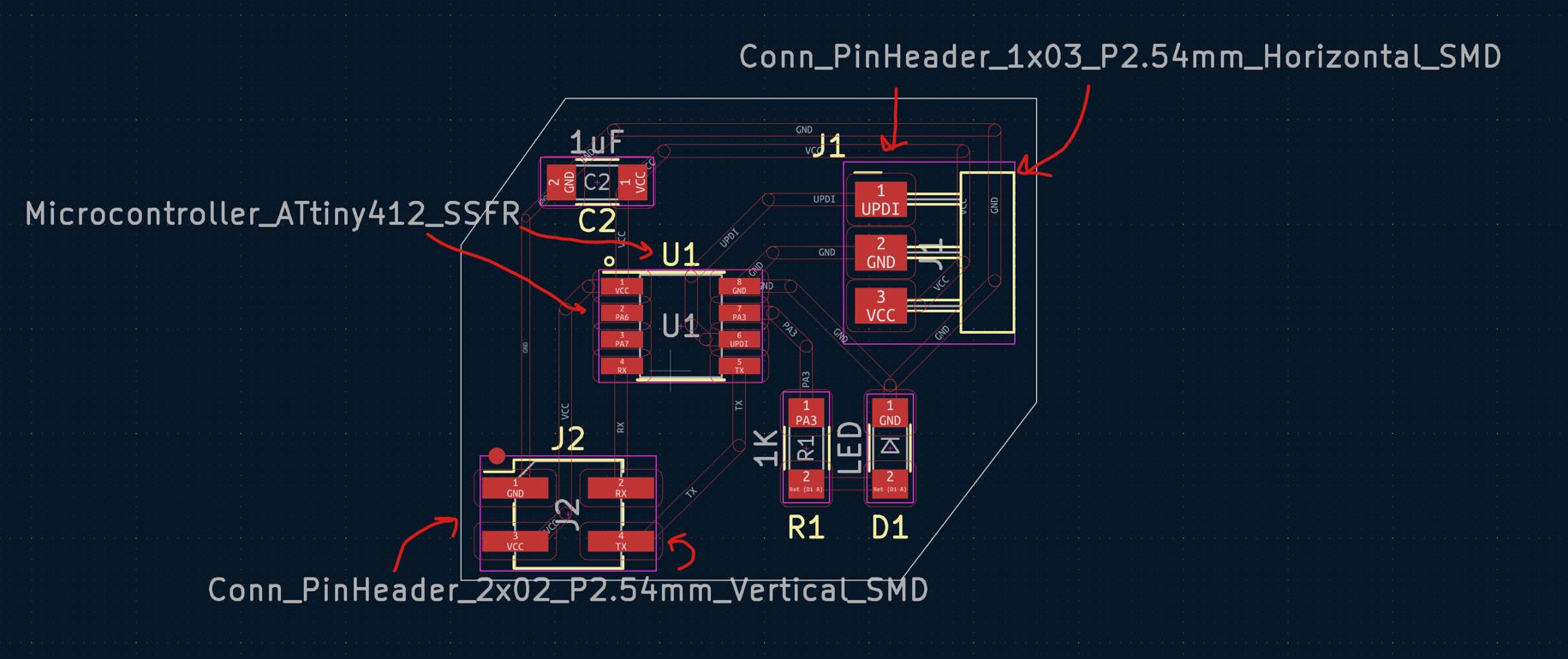
So for this week I began by designing a bridge board through KiCad. I based the schematic on a board I found on Adrians website.I used KiCad to create it, then I put it through Inkscape and used stroke to path on the lines, inverted the colours and saved it as an svg (SVG accessable at bottom of page)
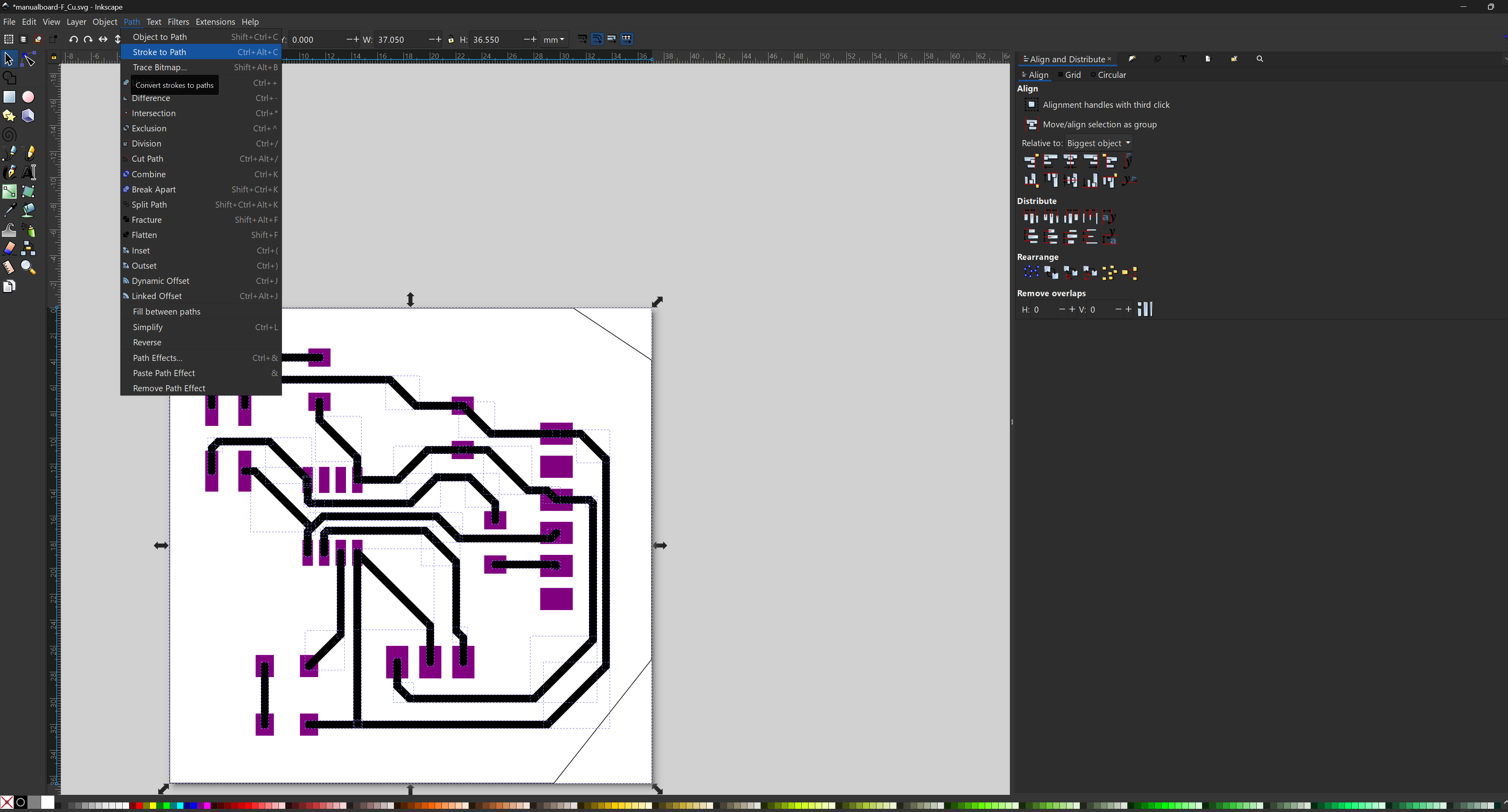
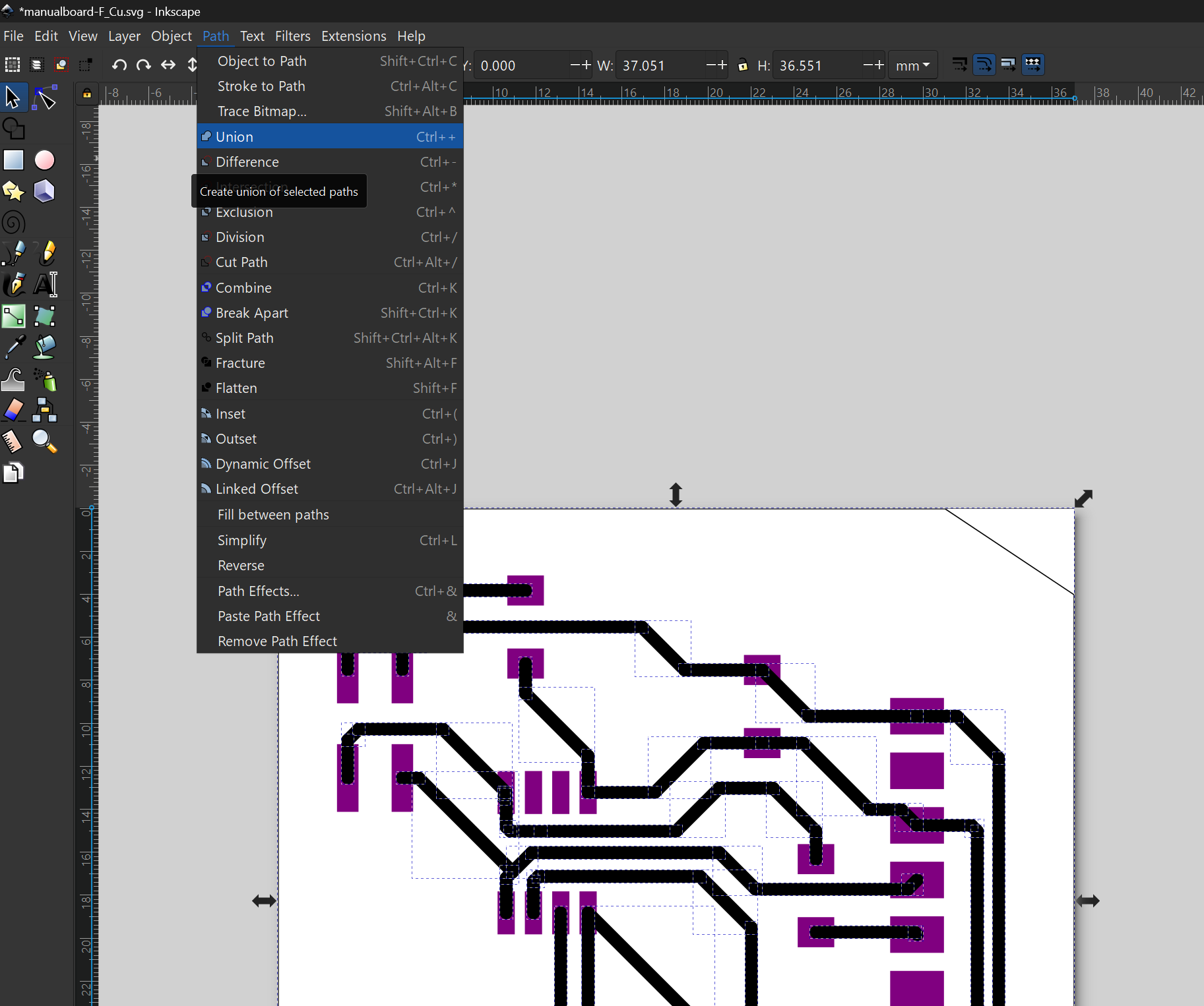
After going though the Inkscape process I went on modsproject.org and went through the same process as I did for the Electronic Production week
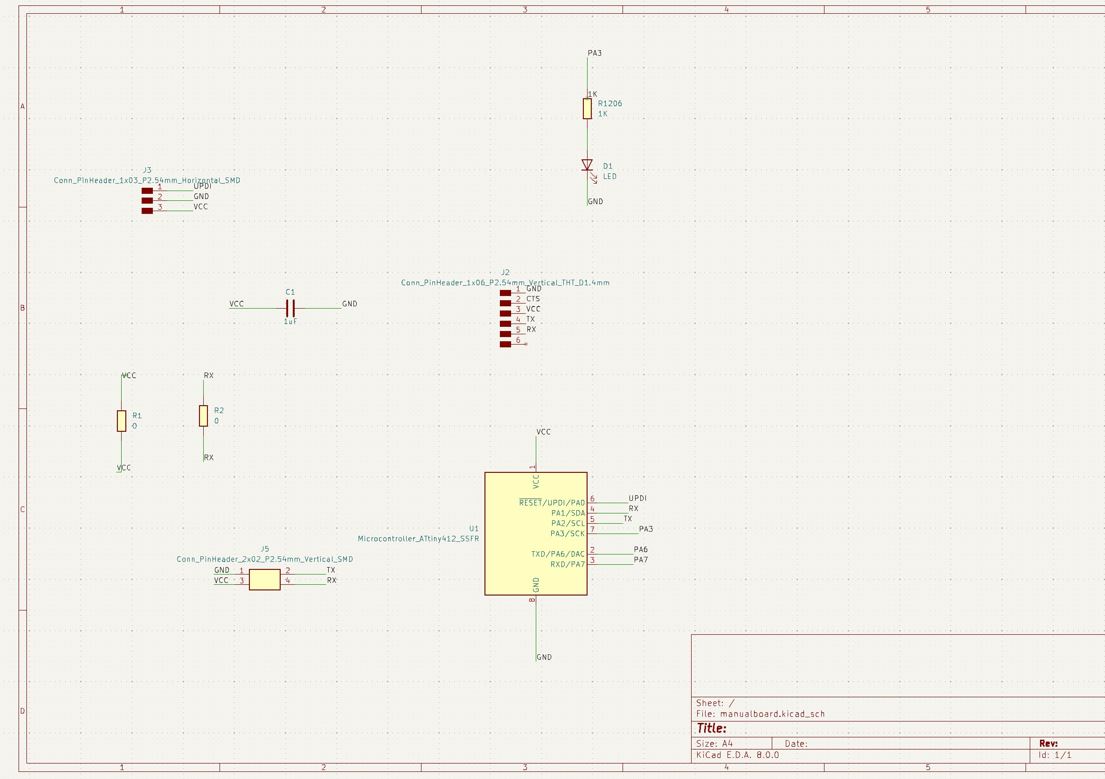
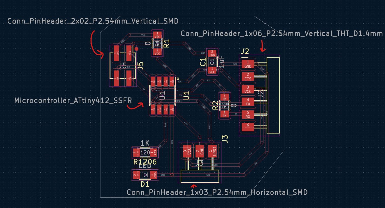
Here is the schematic and the PCB design!
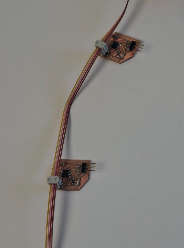
Node
I also made a Node board, largely basing it on the board
made by Adrian in his Networking
week!.
I followed his documentation regarding the parts and created
my own version through KiCad.
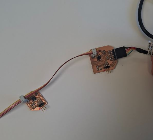
Connecting it
Next step was to connect the boards together with wires:
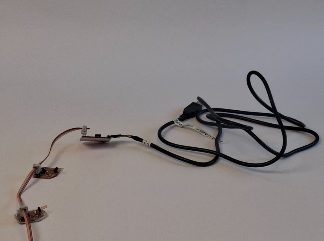
Node<-Node<-Bridge<-FTDI cable<-Computer
So to prepare my computer I began by downloading the driver needed for the FTDI cable
driver download link
The next step will be to get it to work through code :)
I will continue to largely base it off Adrian´s work
Link to Adrians page
CODING
To begin it is important to realize the setup of the parts.
Like previously stated, this particular compartment of
parts consists of
- FTDI Cable
- Bridge
- Node #1
- Node #3
The main goal is to connect the pieces together and create
a program that can reach throughout the different parts. In
Adrian´s documentation he stated the importance of naming
each node! So we will name ours 2 and 3 (just to change it
up a little).
We will do so using Adrian's code. I used Chat GPT to
make slight changes to the code and then uploaded the code
onto the Arduino (as seen below)
BRIDGE CODES:
Adrians code://code made by Adrián Torres //Fab Academy 2020 //Fab Lab León //ATtiny412 bridge int v=0; int nodeid=1; //Node Identification void setup() { Serial.begin(115200); //initialize serial communications pinMode(4, OUTPUT); // led } void loop() { while (Serial.available () == 0 ) {} v = Serial.parseInt(); Serial.println(v); if(v == nodeid) //If the value of v equals the identification of the node { digitalWrite(4,HIGH); delay(1000); digitalWrite(4,LOW); delay(1000); } else { digitalWrite(4,LOW); } }
I then asked ChatGPT to explain the code to me step by step and help me change it using the following promt:
"You are a coding expert I hear! can you explain this code? (for context this code is used in the Arduino coding enviroment)*insert Adrian´s code*"Chat GPT proceeded to give an explanation of what each part of the code meant, hence giving me a better understanding of how the code can be modified.
Modified code (Bridge):
 // Code by Adrián Torres, modified for multiple nodes by ChatGPT
// Fab Academy 2020 | Fab Lab León | ATtiny412 multi-node bridge

int v = 0;
const int nodeid = 1;  // <-- Change this number for each node (e.g., 1, 2, 3...)
const int ledPin = 4;

void setup() {
  Serial.begin(115200);       // Initialize serial communications
  pinMode(ledPin, OUTPUT);    // Set LED pin as output
}

void loop() {
  if (Serial.available() > 0) {
    v = Serial.parseInt();     // Read an integer from serial
    Serial.println(v);         // Echo it back for debugging

    if (v == nodeid) {
      blinkLED();              // Blink if it's this node's ID
    } else {
      digitalWrite(ledPin, LOW); // Ensure LED is off otherwise
    }
  }
}

void blinkLED() {
  digitalWrite(ledPin, HIGH);
  delay(1000);
  digitalWrite(ledPin, LOW);
  delay(1000);
}
NODES CODES
Here is the original code by Adrián://code made by Adrián Torres
//Fab Academy 2020
//Fab Lab León
//ATtiny412 node 1
#include <SoftwareSerial.h>
SoftwareSerial mySerial(2,3); //RX, TX
int v=0;
int nodeid=2;//Node Identification
void setup() {
mySerial.begin(115200); //initialize serial communications
pinMode(4, OUTPUT); // led
}
void loop() {
while (mySerial.available () == 0 ) {} //while serial is 0
v = mySerial.parseInt();
mySerial.println(v);
if(v == nodeid) //If the value of v equals the identification of the node
{
digitalWrite(4,HIGH);
delay(200);
digitalWrite(4,LOW);
delay(200);
}
else
{
digitalWrite(4,LOW);
}
}I made small changes with the help of GPT and also changed the nodeid myself, I thought 3 was a solid number so I made made the node id 3 (meaning I named the node 3)
Prompt used:
"add to blink 5 times in the beginning of the program for 500 milliseconds"
node 1
// code originally made by Adrián Torres
// Fab Academy 2020
// Fab Lab León
// ATtiny412 node 1
// Modified to blink LED 5 times at startup

#include <SoftwareSerial.h>
SoftwareSerial mySerial(2, 3); // RX, TX

int v = 0;
int nodeid = 1; // Node Identification

void setup() {
  mySerial.begin(115200); // initialize serial communications
  pinMode(4, OUTPUT);      // LED on pin 4

  // Blink LED 5 times at startup (500 ms total per blink: 250 ms ON + 250 ms OFF)
  for (int i = 0; i < 5; i++) {
    digitalWrite(4, HIGH);
    delay(250);
    digitalWrite(4, LOW);
    delay(250);
  }
}

void loop() {
  while (mySerial.available() == 0) {} // Wait for incoming serial data

  v = mySerial.parseInt();    // Read the received integer
  mySerial.println(v);        // Echo back for debugging

  if (v == nodeid) {          // If the message is for this node
    digitalWrite(4, HIGH);
    delay(800);
    digitalWrite(4, LOW);
    delay(800);
  } else {
    digitalWrite(4, LOW);     // Otherwise, keep the LED off
  }
}
Node 3
// code originally made by Adrián Torres
// Fab Academy 2020
// Fab Lab León
// ATtiny412 node 3
// Modified to blink LED 5 times at startup
#include <SoftwareSerial.h>
SoftwareSerial mySerial(2, 3); // RX, TX
int v = 0;
int nodeid = 3; // Node Identification
void setup() {
mySerial.begin(115200); // initialize serial communications
pinMode(4, OUTPUT); // LED on pin 4
// Blink LED 5 times at startup (500 ms total per blink: 250 ms ON + 250 ms OFF)
for (int i = 0; i < 5; i++) {
digitalWrite(4, HIGH);
delay(250);
digitalWrite(4, LOW);
delay(250);
}
}
void loop() {
while (mySerial.available() == 0) {} // Wait for incoming serial data
v = mySerial.parseInt(); // Read the received integer
mySerial.println(v); // Echo back for debugging
if (v == nodeid) { // If the message is for this node
digitalWrite(4, HIGH);
delay(800);
digitalWrite(4, LOW);
delay(800);
} else {
digitalWrite(4, LOW); // Otherwise, keep the LED off
}
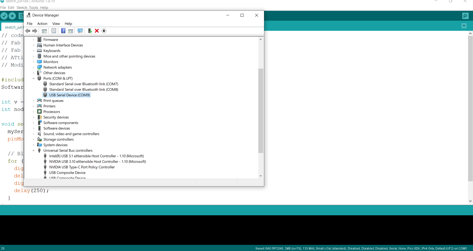
}I connected the board to the computer (note it is important to make sure to select the right port, you can verify which port it is by going into the computer manager and inserting the device and removing it to see which one the desired device is connected to, in this case it was PORT COM9.
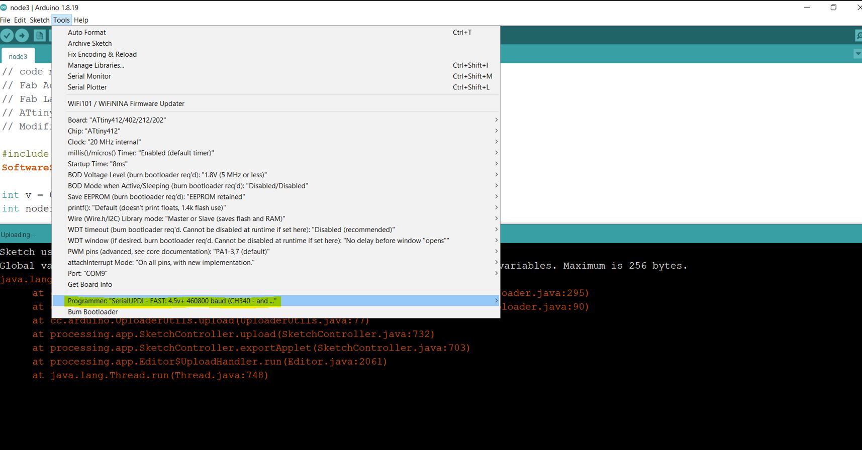
To upload the code via programmer I used the following programmer: SerialUPDI - FAST: 4.5v+ 460800 baud (CH340- and maybe some others)
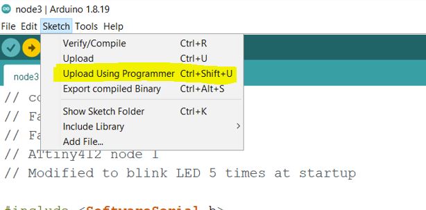
When uploading the code I use the Upload Using Programmer option (Ctrl+Shift+U)
At first when I uploaded the code through the Arduino workspace the code did not work despite having the right port selected.
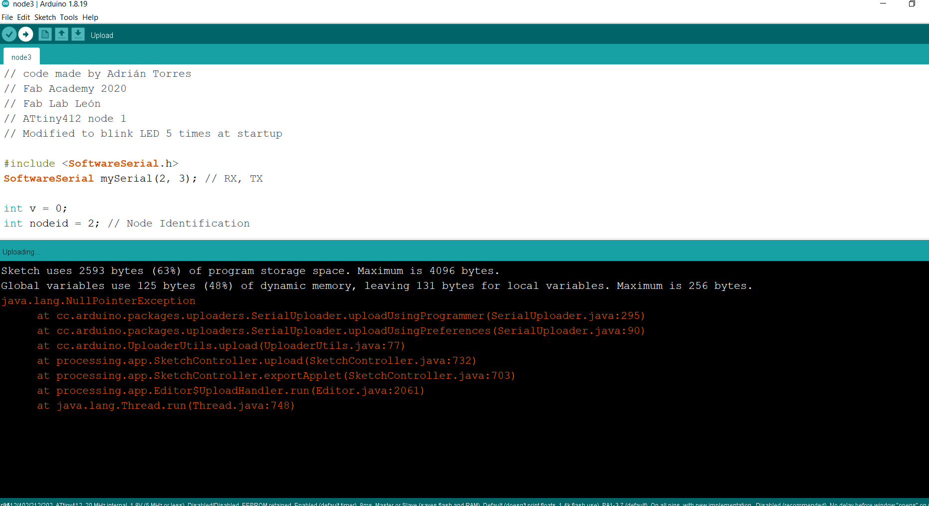
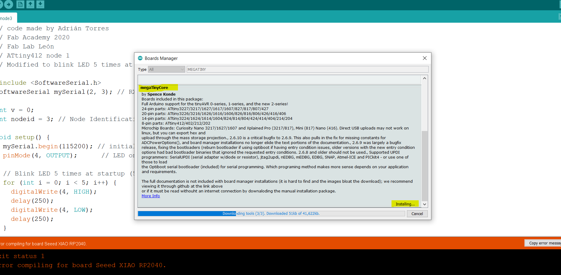
Luckily this was an easy fix since my instructor noticed that I did not have the right tools for it. All that I needed to add was the megaTinyCore pack and I was set.
side note: to access the megaTinyCore pack you need to find it in the Library Manager that you can access through the tools tab on top of the screen.
In the end it worked! To try it I went to the serial monitor and typed the numbers chosen for the nodes (in this case 1 and 3).
Please note if you plan on doing this you need to put the program towards one board at a time.
Video proof that the codes worked:
Software
https://www.kicad.org/
https://www.arduino.cc/
https://openai.com/index/chatgpt/
Bridge files
KICAD
Bridge
PCB
Bridge
PRL
Bridge
PRO
Bridge
SCH
other
Bridge interior
svg sv
Bridge traces svg
interior rml
traces rml
Node Files
KICAD
NODE
PCB
NODE
PRL
NODE
PRO
NODE
SCH
other
Node interior svg
Node Traces svg
interior rml
traces rml