

We have just finish week #15. It was an interesting week for me because I decided to use a new machine that wasn't part of any assignments during Fablab Academy. I had some problems but I learn a lot of the sewing process. Now, a new week has just started and it´s about working on my final project. So by now I have work on it, I think I have maybe 55% - 65%..... I hope so. As last week there isn't a group assignment to do. I'm going to focus on a design that integrates my final project. Maybe by the end of this week the percentage is up to an 80%. So, lets begin and as always hoping for the best. Join me in this week journey and see what comes up.


This week assignmets are:
Group assignments:
Individual assignments:
In this part i'm going to document how i'm going to integrate everything I need into my project. Before I start my assignment for this week I decided to sketch the design and have a much better understanding of what I want it. I think it´s a good starting point. And just to remeber this are the components and circuit i'm going to use:
This first part will help me know how can I integrate all my components, like a starting point. And also will help make some changes in case they are need it. So i'm sharing the initial skethes, so lets see with what do we end up.
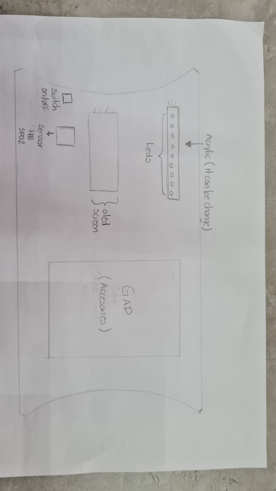
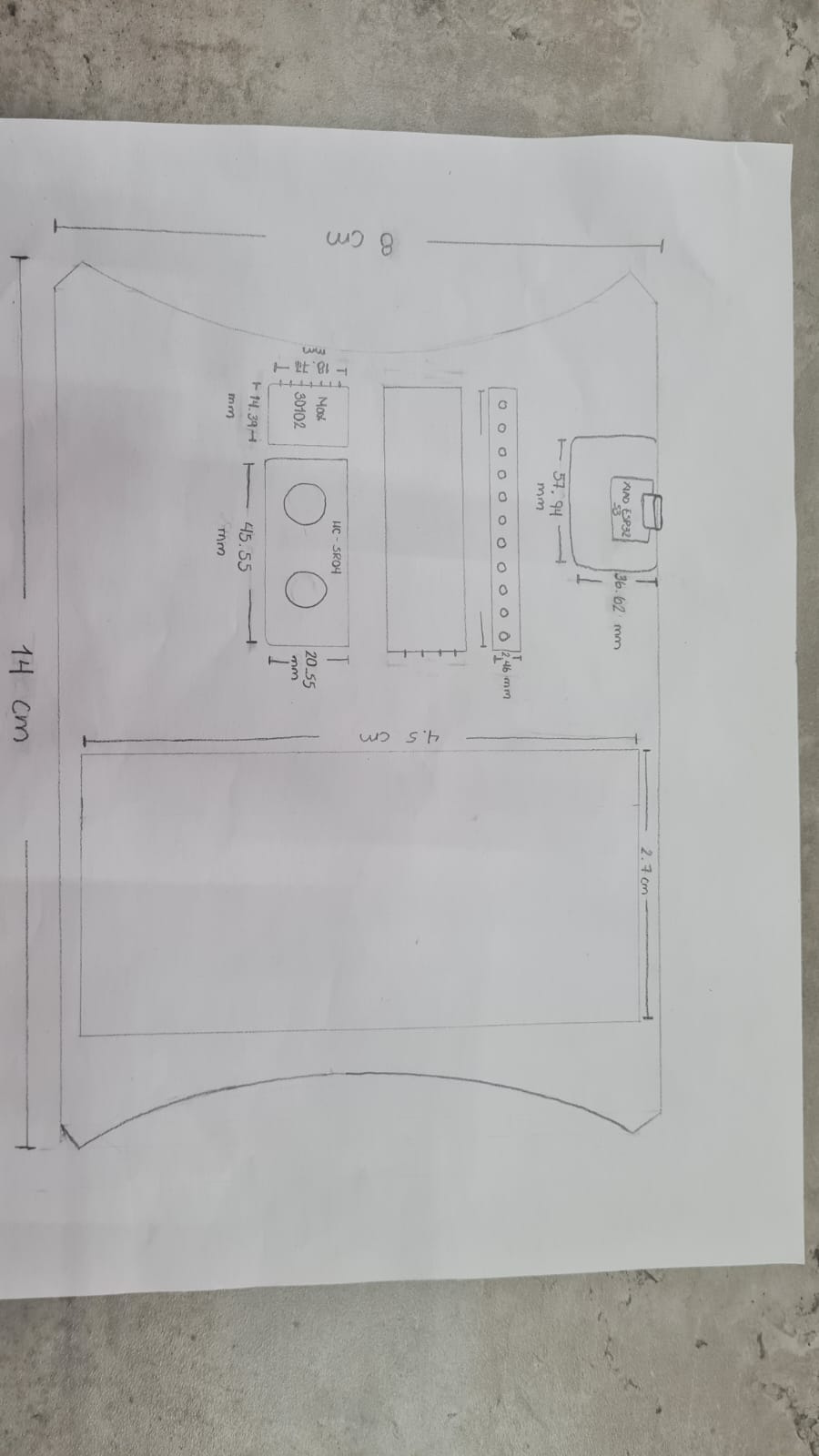
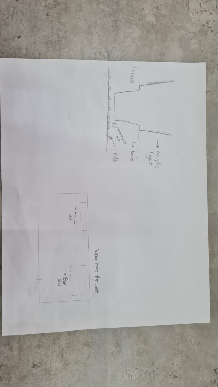
This are the components and pins i'm using en each one of them:
| List of components and pin connection | |||
|---|---|---|---|
 Data from: Xiao ESP32S3 |
14 pins: D0 - D10, 3v3, GND, 5V | 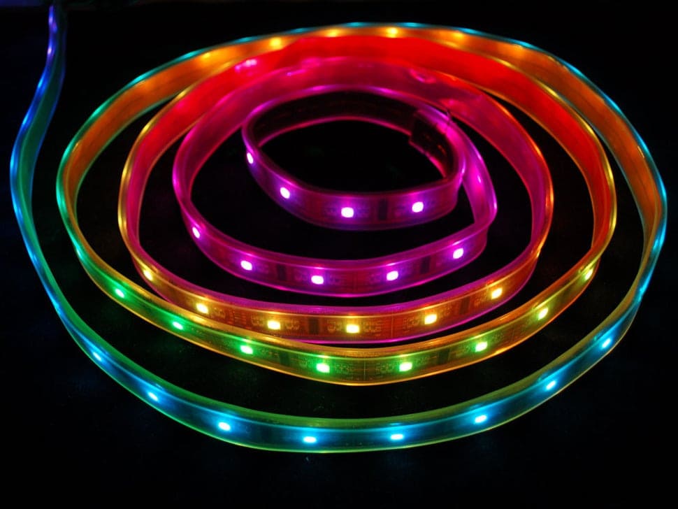 Data from: RGB Led |
3 pins: + ,GND, Data |
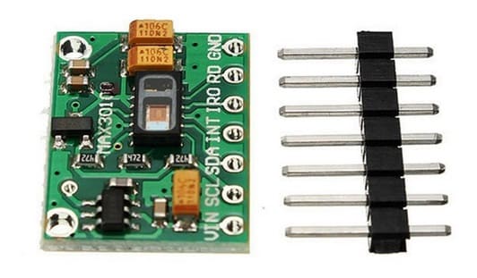 Data from: Max30102 |
4 pins: +, GND, SDA, SCL |  Data from: LCD screen |
3 pins: + ,GND, Data |
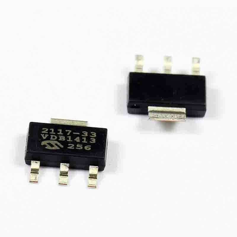 Data from: Voltage regulator |
3 pins: 5v, 3.3v, GND | ||
In the image i'll specify were i'm going to connect each component:
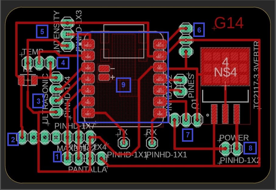
Now that I have a much better idea of my final project. I have to integrate the components in my design and specify where i´m placing each one of them and how i'm going to connect them. So, lets go step by step, in first place im going to show the design of how i'm going to assemble each component.
So i'm starting by making a design integration in Solidworks. This what I did:
This is how start it. But, as I work carfully on my design I made some changes becuase I need to be carefully on how i'm going to place every component on my design.
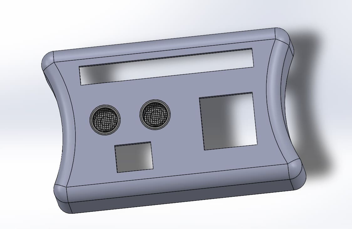
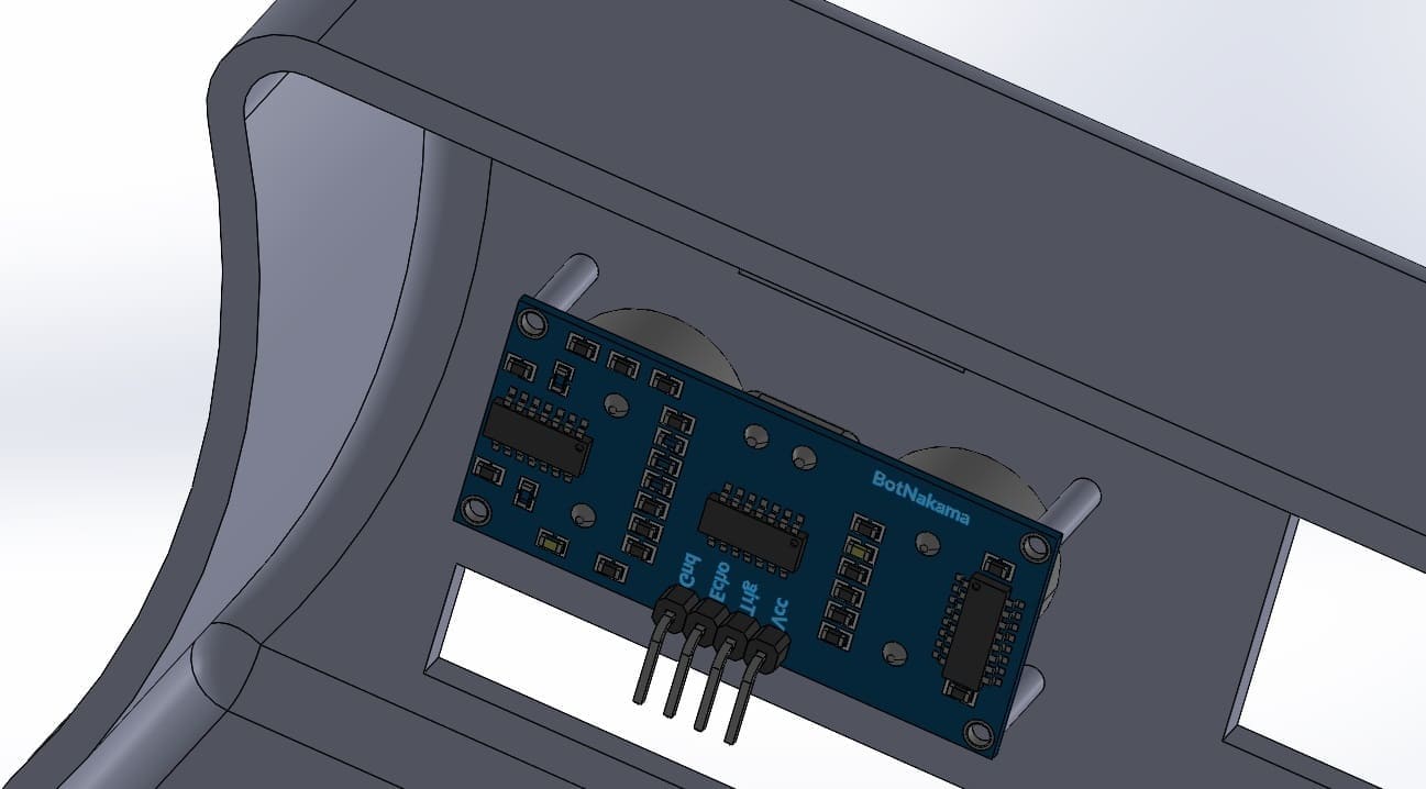
Next I integrated the Max30102. For this part I had to consider how I was going to place it in my design. So I added some details, let me share a few things I did:
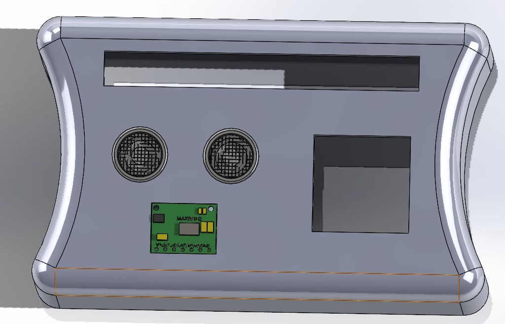
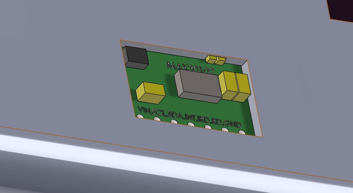
Then I place the oled screen.
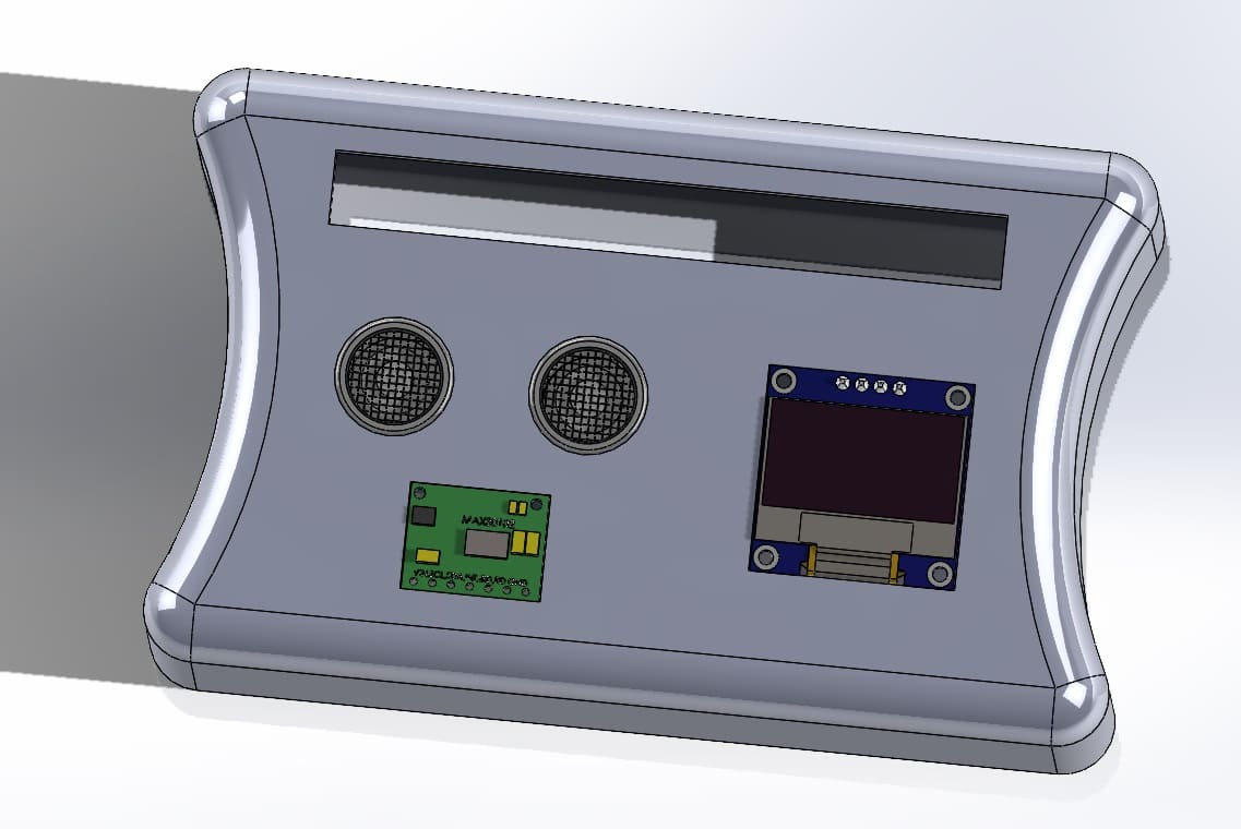
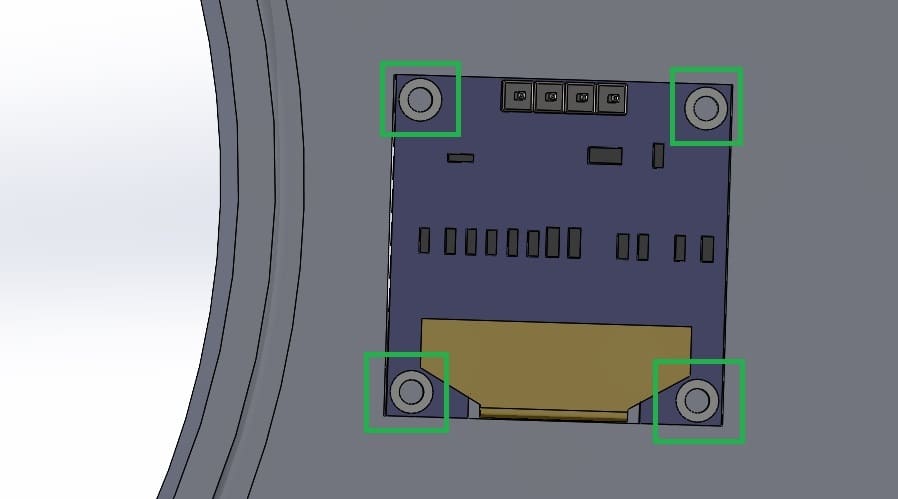
In this part evertything was going fine, but I wasn't sure once I was looking at the "whole picture". So I decided to make some changes, for example:
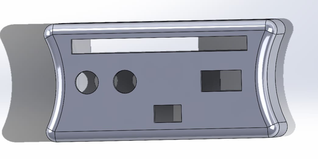
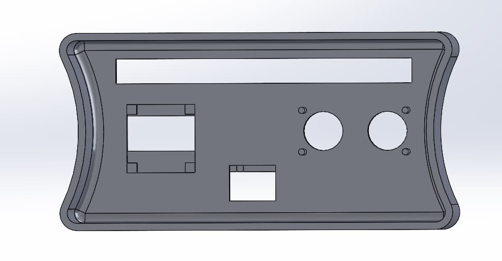
For the next part and once I made the changes I added the leds.
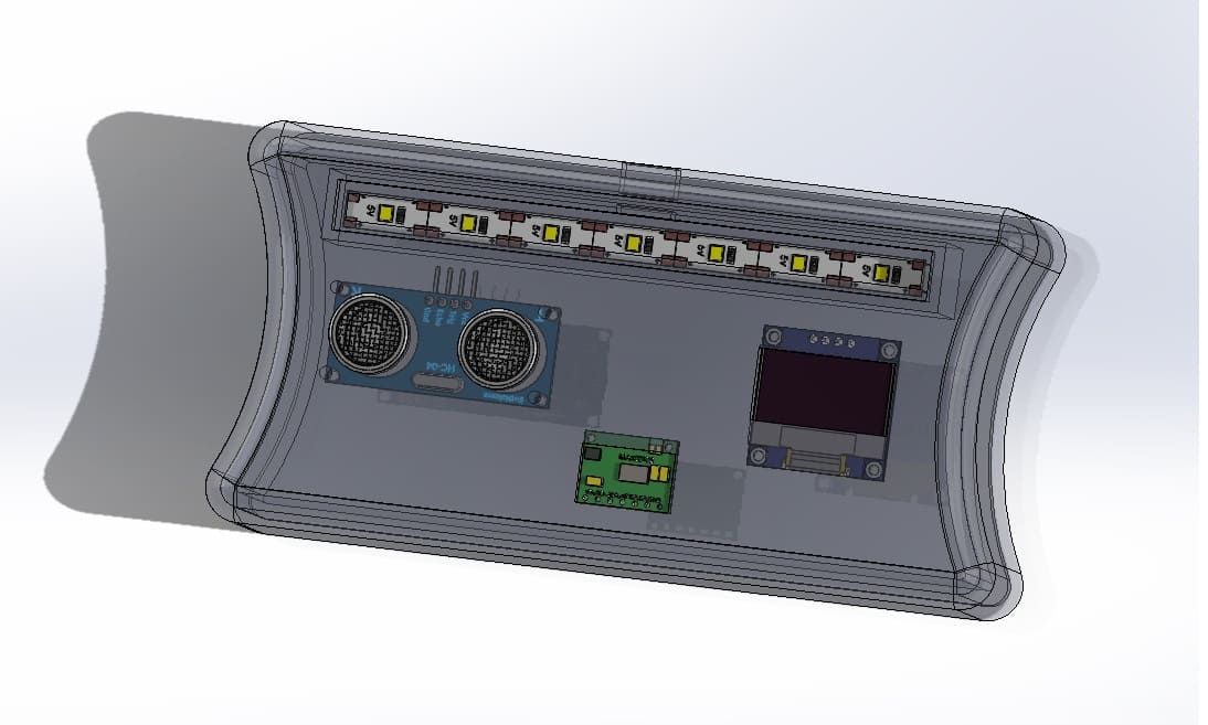
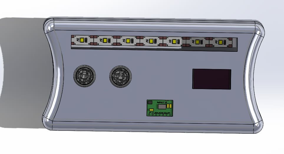
Then I design the back part or the bottom part. And make more changes as I assemble each part. The changes I made were:
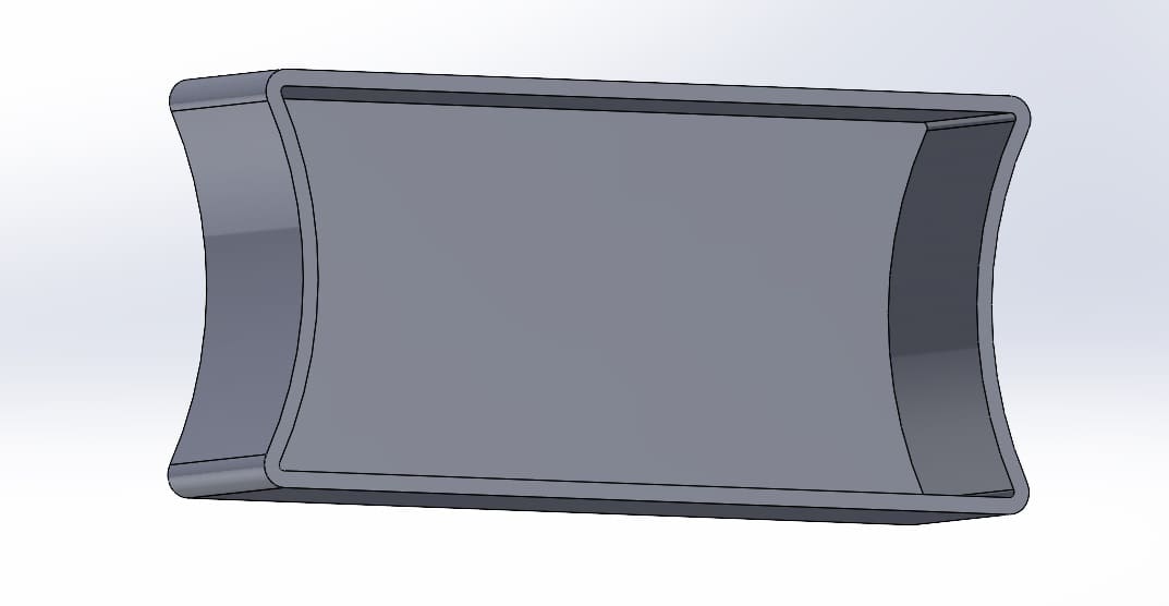
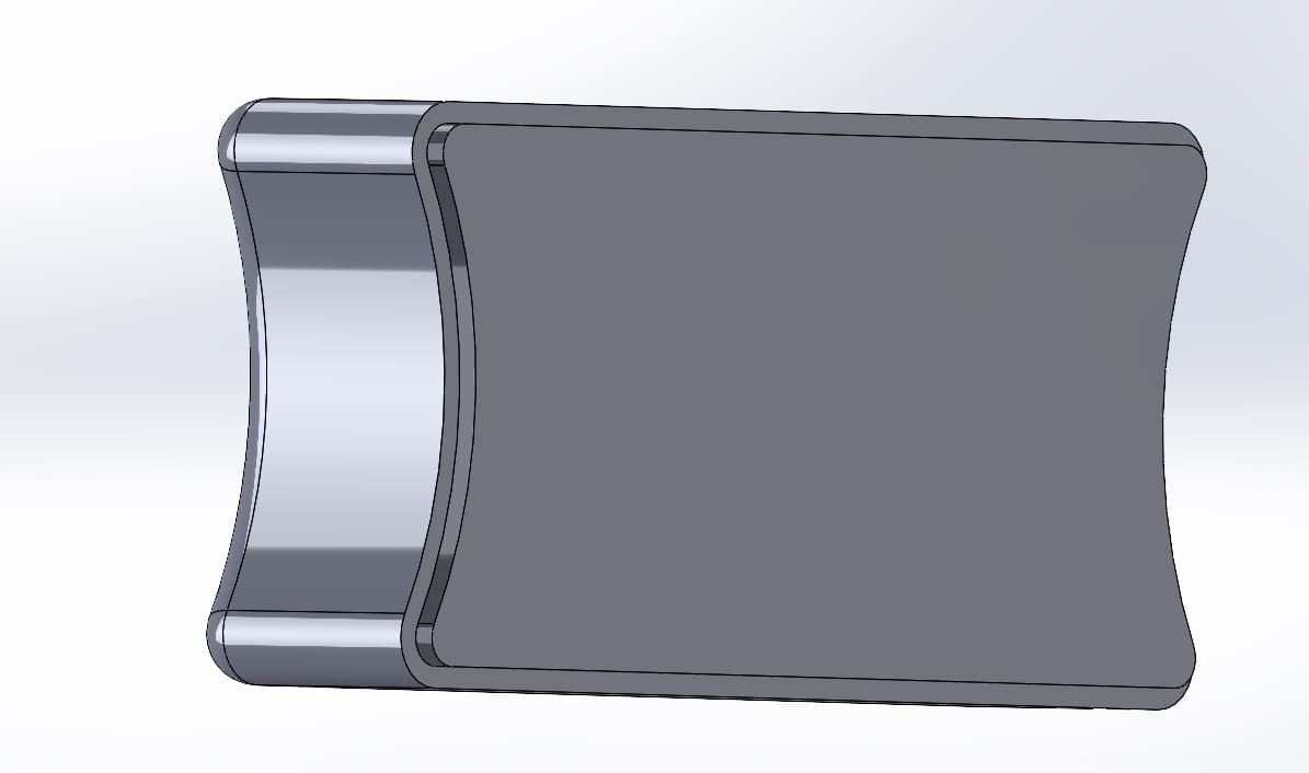
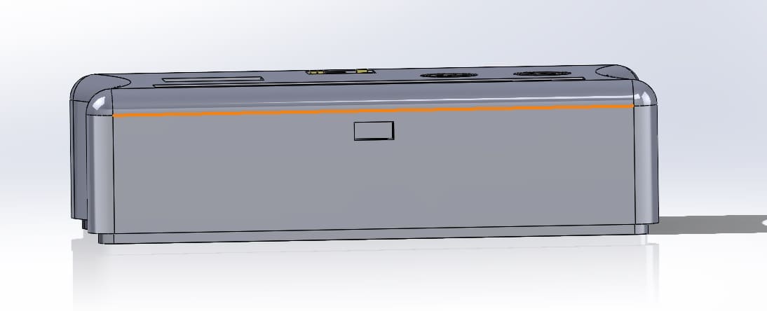
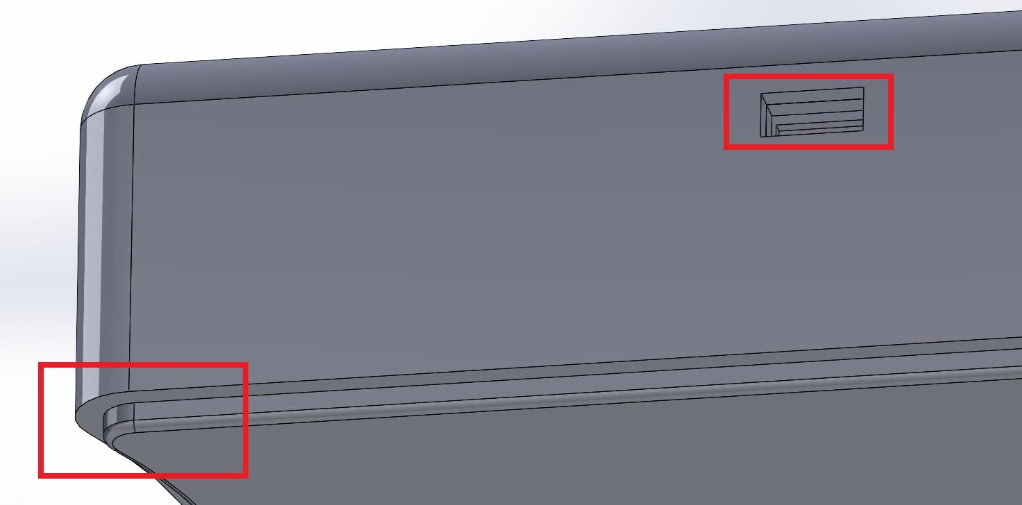
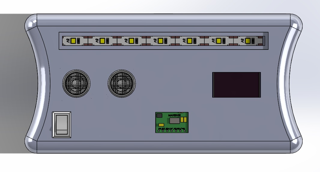
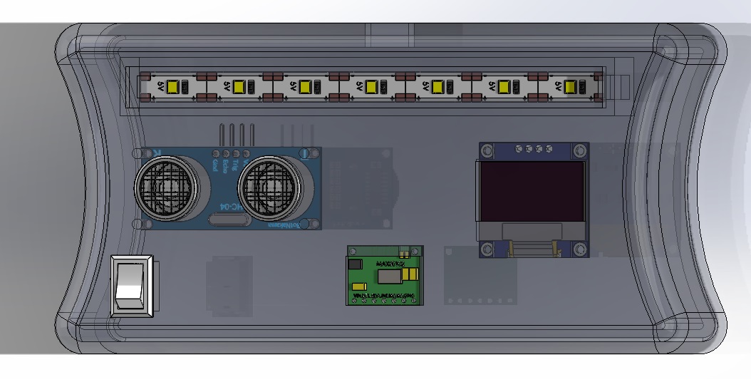
Now that I have the design integration, I can consider the wiring part. In this section I'll show how I am going to connect every component and not make a mess. I need to be careful and decide how to connect everything for my final project.
Focusing in my design i'm showing how will I connect the components to the Xiao.

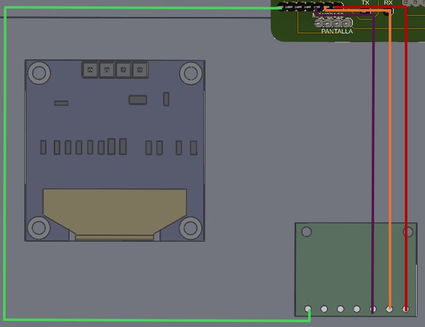
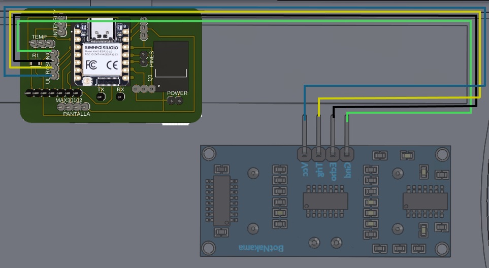
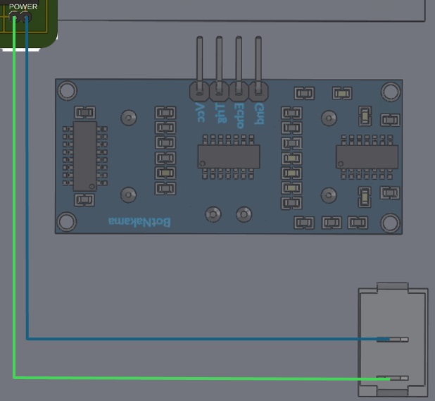
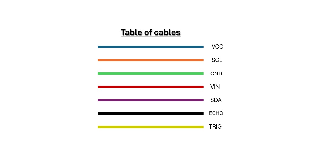
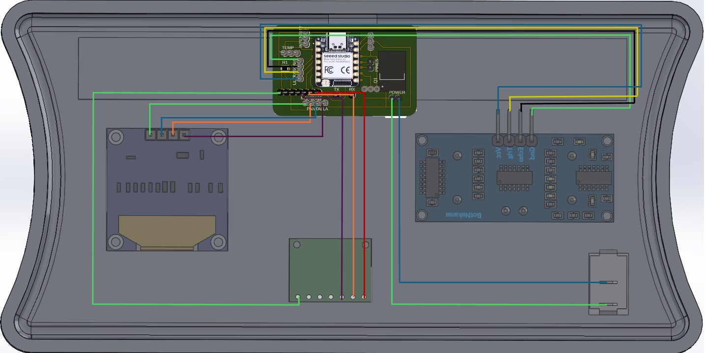
In this part i'll share the designs I downloaded from grabcad and my final design
Here are the files of my assembly
What did I learn in this week?