
This is the process of my final project:
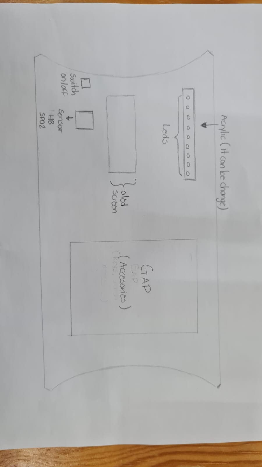
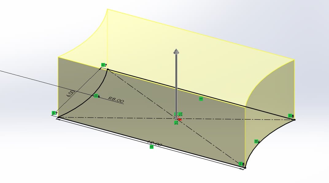
I've decided that im going to build a lamp. I want it to be a personalize lamp, to which some details can be changed:
let me give you some details:
I had this idea one day I was at my grandmother house. She told me that she need it a "different lamp", I thought her lamp broke down or maybe the bulb burn out or something like that. But the thing was that she want to me to cut in half two lamp and change their bases. She thought that because the lamps look similar, cutting and changing could be done easily. So, I thought, is there something similiar in the market? So, I think no or at least nothing that I know.
The idea is to have a different desk lamp. This are the functions it will have:


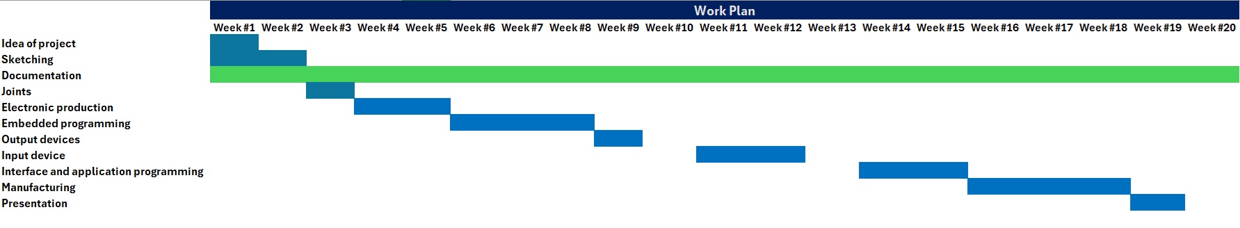
In this section im´ going to add a work plan for my final project of how i'll be working week by week. The idea is to have a plan I can follow to manufacture my project.
In this section im´ going to add information I will need for my final project. Every week i'm learning new things so I will document what I think i'm going to need from those weeks.
Since I started Fablab academy i've been learning lots of things. So i'm documenting some things I consider important and that will help me in my final project.


During this week I learn about elctronics design. During this week assingnments I had to design a PCB board. This is not my design but it's an example of what i'm talking about. So when I design my board I will share it, but this gives me a good idea of what I need to consider, everything I want the lamp to do.
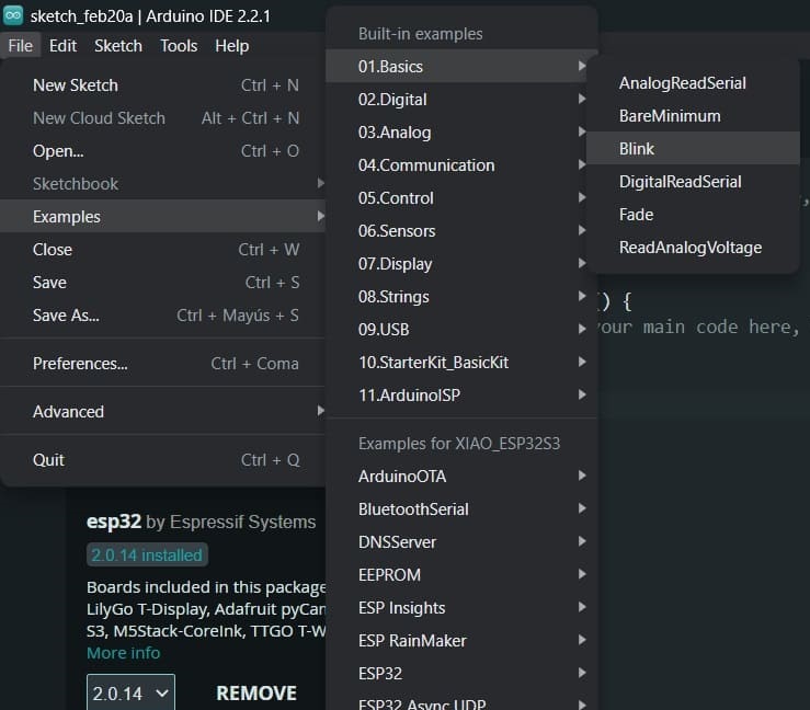
This was an interesting week, it was about embedded programming. I never program a component so for this part I had to understand about:
Becasuse I need to program the components I will be using in my lamp. This is very important that I understand, I think some weeks later we are going to be using more about programming components and connecting them to a board that will be controlled by a processor.


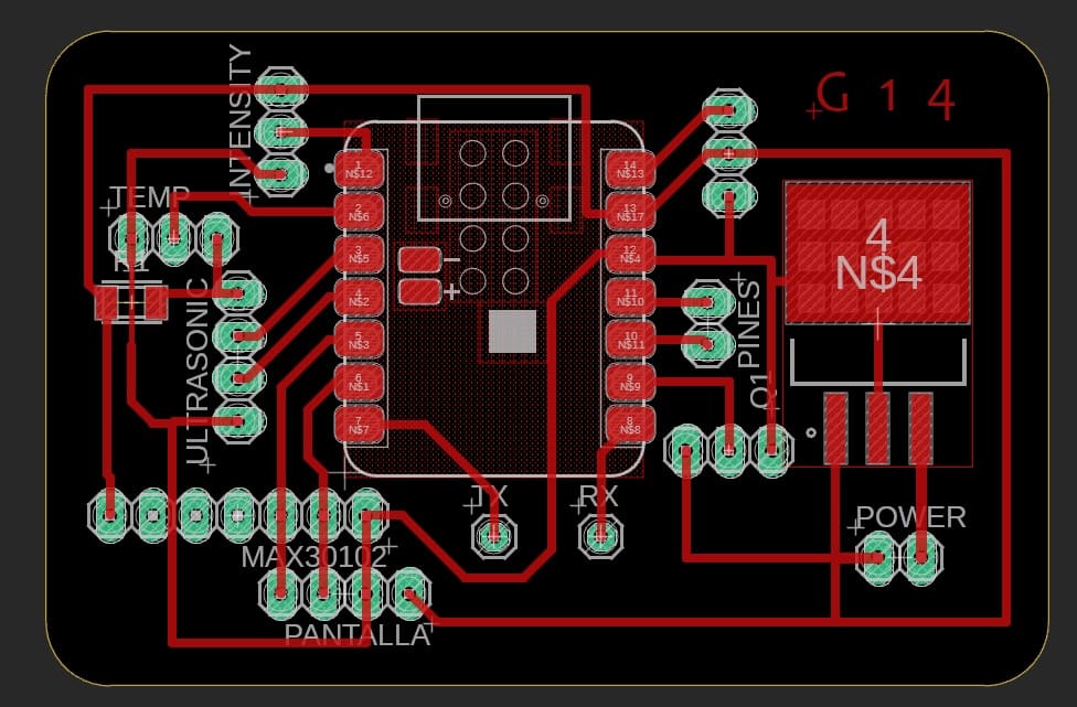
During week #8 its similar to week #6. During this week I had to design a PCB board, so I decided to make the one i'm going to use during my project. Now, I need to consider the components i'm using before sarting the design. Another important thing is understanding how to connect those components.
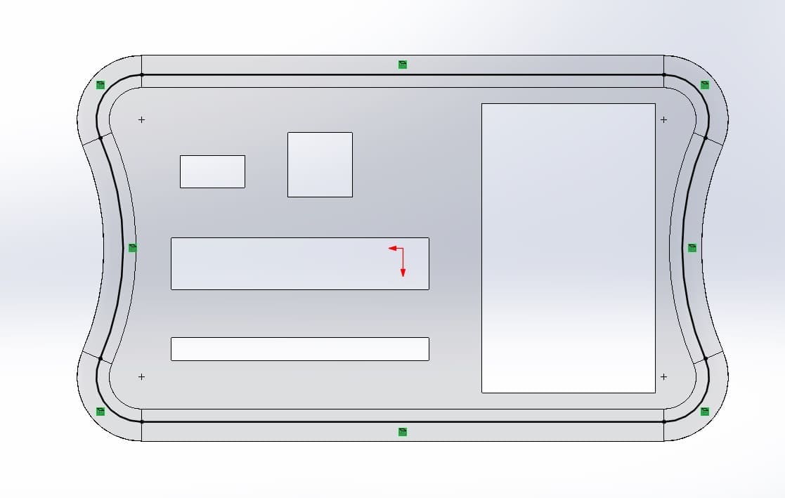
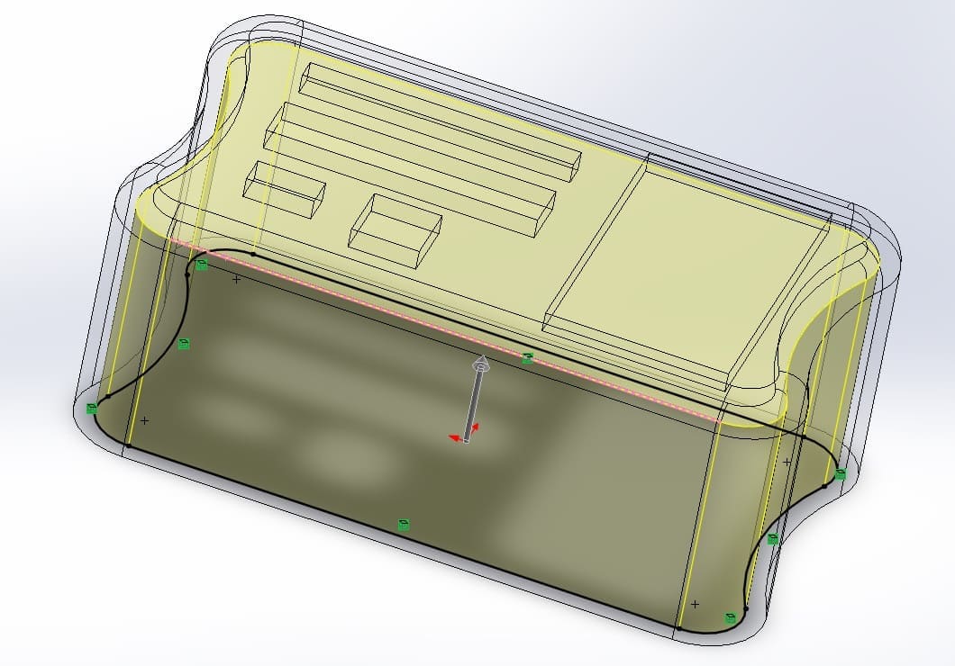
Before desinging:
This is the design:

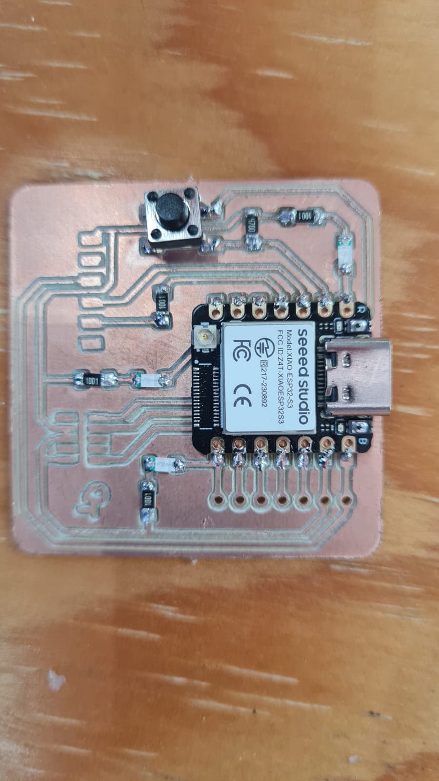
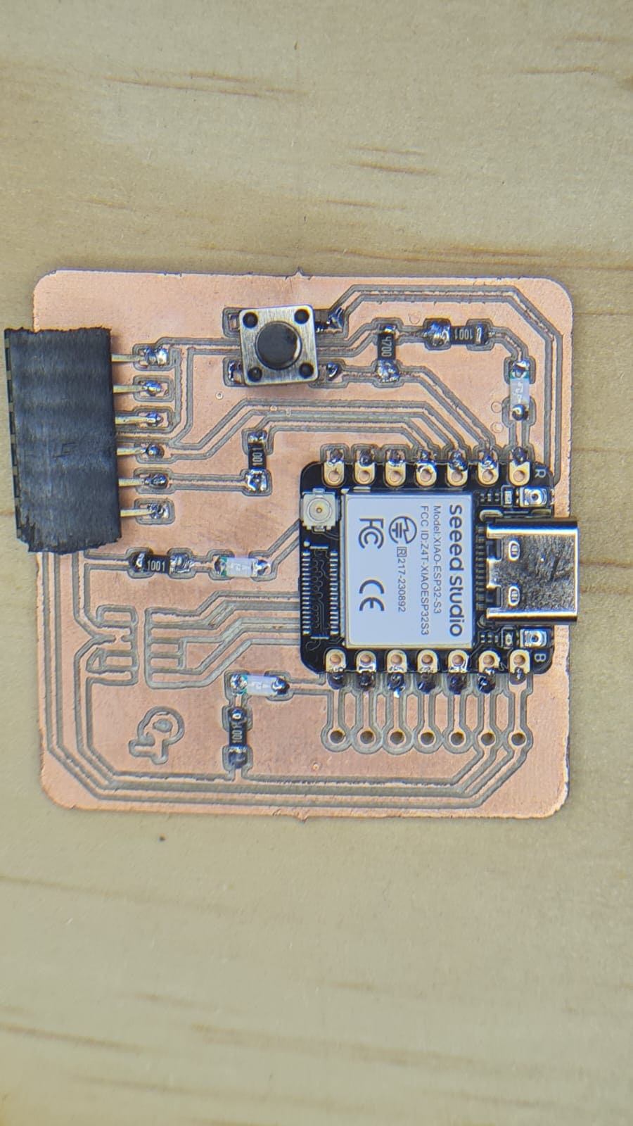
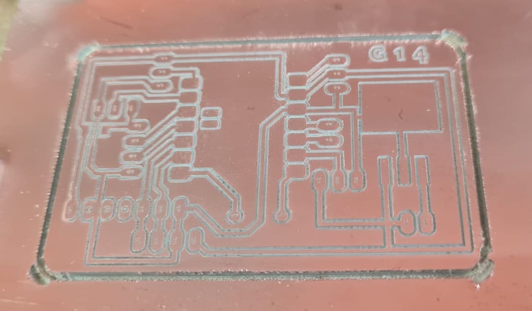
Here's an imagen and a video of the printing process of the PCB board i'll be using for my final project.
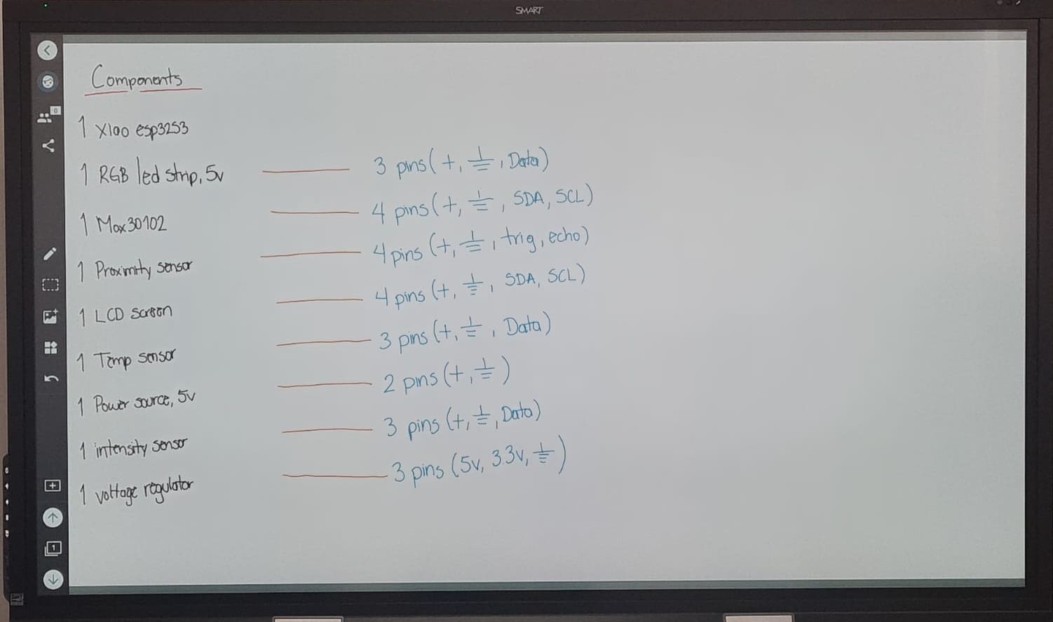
This are the components and a little description about them:
| List of components | |||
|---|---|---|---|
 |
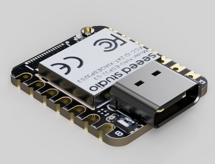
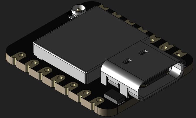
Is a diminutive development boards, sharing a similar hardware structure, where the size is literally thumb-sized. Integrates camera sensor,
digital microphone and SD card supporting. Combining embedded ML computing power and photography capability, this development board can
be your great tool to get started with intelligent voice and vision AI.
Data from: Xiao ESP32S3 |
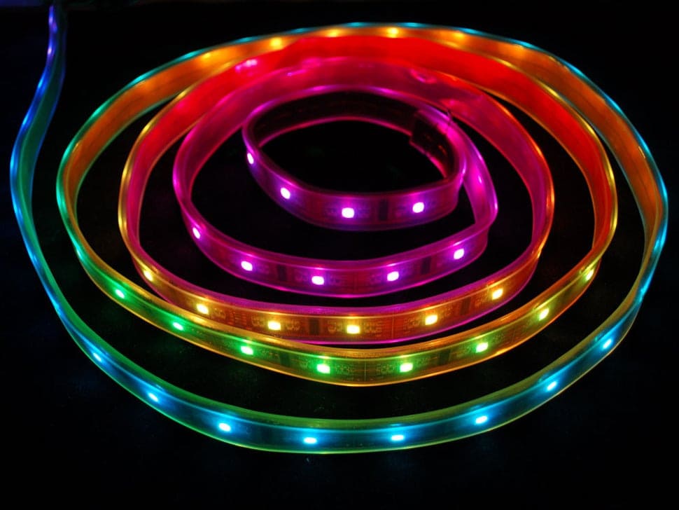 |
RGB LED stands for Red Blue Green Light Emitting Diode, which refers to the three hues of light that are generated in these LED strip lights.
The LED strips use a combination of different brightness levels in each of the three colours to generate a full spectrum of colour.
Data from: RGB Led |
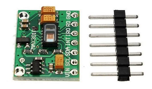 |
Is an integrated pulse oximetry and heart-rate monitor module. It includes internal LEDs, photodetectors, optical elements, and low-noise electronics
with ambient light rejection. It provides a complete system solution to ease the design-in process for mobile and wearable devices.
Data from: Max30102 |
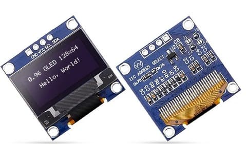 |
The SSD1306 display is an OLED that is controlled by the SSD1306 micro-chip driver, which acts as a bridge between the display matrix and the microcontroller. Despite
the size, these displays are very functional and capable of displaying complex images.
Data from: LCD screen |
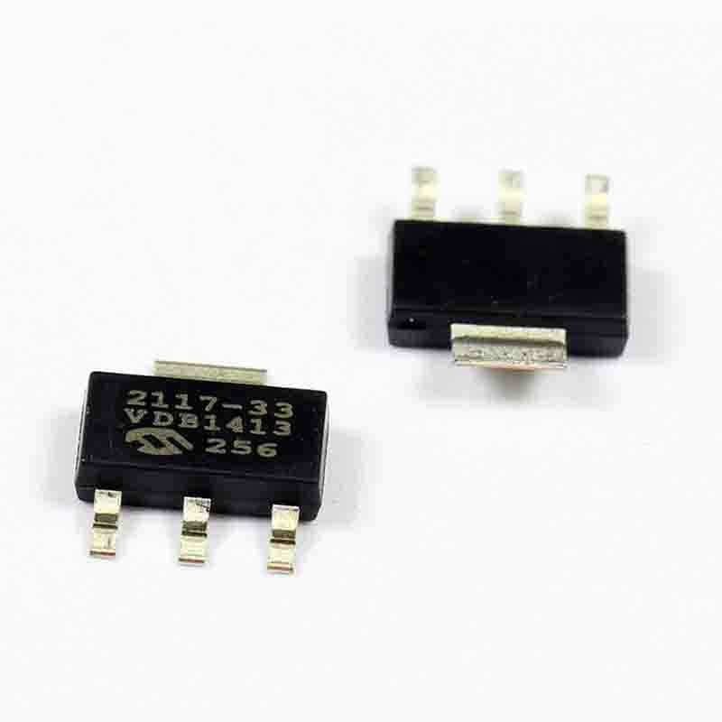 |
Is a fixed, high accuracy (typically ±0.5%) CMOS low dropout regulator. Designed specifically for battery-operated systems, the TC2117’s CMOS construction eliminates wasted ground current,
significantly extending battery life.
Data from: Voltage regulator |
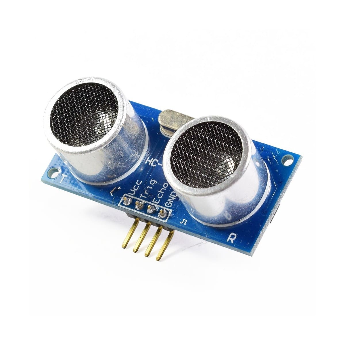 |
HC-SR04 stands for High-Conductance Ultrasonic Sensor consists of a transmitter and receiver. The sensor measures how far things are without touching them and it uses
sound waves to get the measurements right. It can work well when things are between two to four centimeters away. So, it’s good for things that are around two to four centimeters away.
Data from: Ultrasonic sensor |
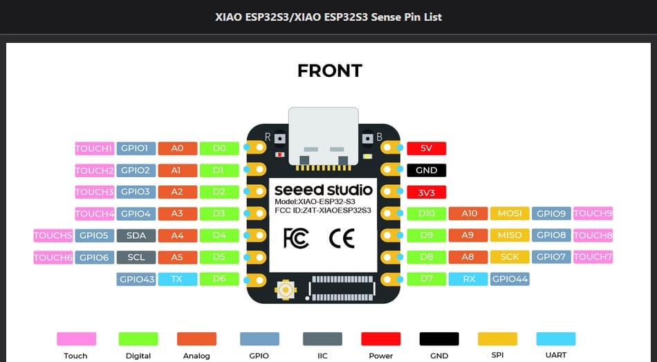
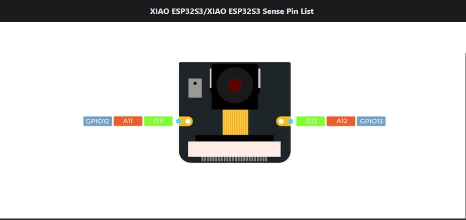
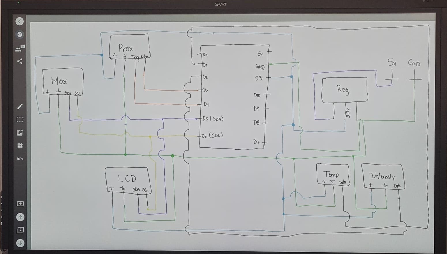
In the image i'll specify were i'm going to connect each component:
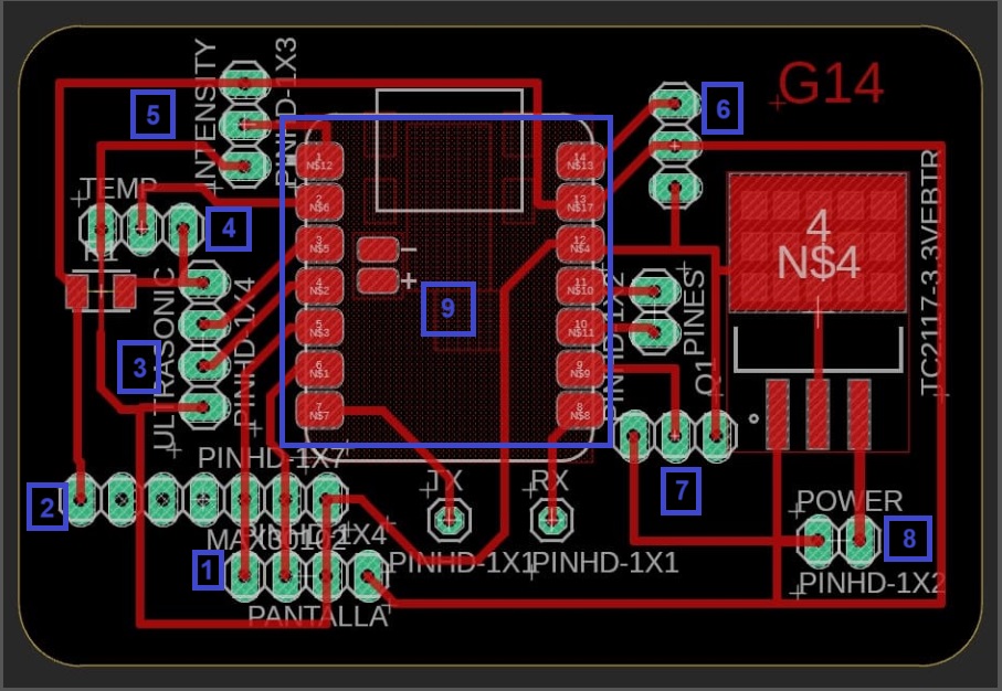
In this part i'm going to detail were to connect the components and which pins I'll be connecting for each one of them.
| Connection pins | |
|---|---|
| 1. Oled screen | 3 pins: + ,GND, Data |
| 2. Max30102 sensor | 4 pins: +, GND, SDA, SCL |
| 3. HC-SR04 sensor | 4 pins: +, Trig, echo |
| 4. DHT22 sensor (optional) | 3 pins: + ,GND, Data |
| 5. Intensity sensor | 3 pins: + ,GND, Data |
| 6. Leds | 3 pins: + ,GND, Data |
| 7. Voltage regulator | 3 pins: 5v, 3.3v, GND |
| 8. Power source | 2 pins: + ,GND |
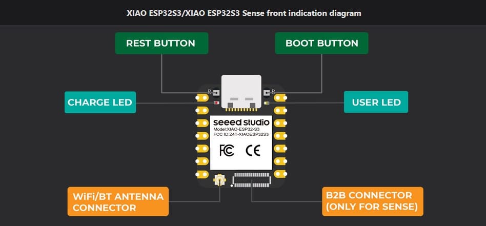
| 9. Xiao ESP32-S3 | 14 pins: D0 - D10, 3v3, GND, 5V |
In this week we work with Output device. The idea during this week was to add an output device to a microcontroller board I've designed and program the device so it can do something. This week I use an Oled screen to see the results of the xiao in it. The idea is to visualiza the measurements of the max30102 sensor in the Oled screen.
What am I considereing from this week:
How to connect it?

In this week is similar to week 11, the difference is that I focus in input devices. My main input device is the max30102 sensor, I need to know about this sensor and how to connect it to my board. So in this part I share with you some information I consider important about the sensor:
The MAX30102 operates on a single 1.8V power supply and a separate 3.3V power supply for the internal LEDs. Communication is through a standard I2C-compatible interface.
Data from: Max30102
The MAX30102 works by shining both lights onto the finger or earlobe (or essentially anywhere where the skin isn’t too thick, so both lights can easily penetrate the tissue) and measuring the amount of reflected light using a photodetector. This method of pulse detection through light is called Photoplethysmogram. The working of MAX30102 can be divided into two parts: Heart Rate Measurement and Pulse Oximetry (measuring the oxygen level of the blood).
The oxygenated hemoglobin (HbO2) in the arterial blood has the characteristic of absorbing IR light. The redder the blood (the higher the hemoglobin), the more IR light is absorbed. As the blood is pumped through the finger with each heartbeat, the amount of reflected light changes, creating a changing waveform at the output of the photodetector. As you continue to shine light and take photodetector readings, you quickly start to get a heart-beat (HR) pulse reading.
Pulse oximetry is based on the principle that the amount of RED and IR light absorbed varies depending on the amount of oxygen in your blood.
Data from: How does it work
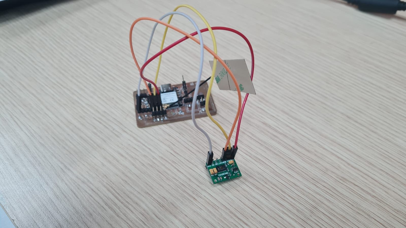
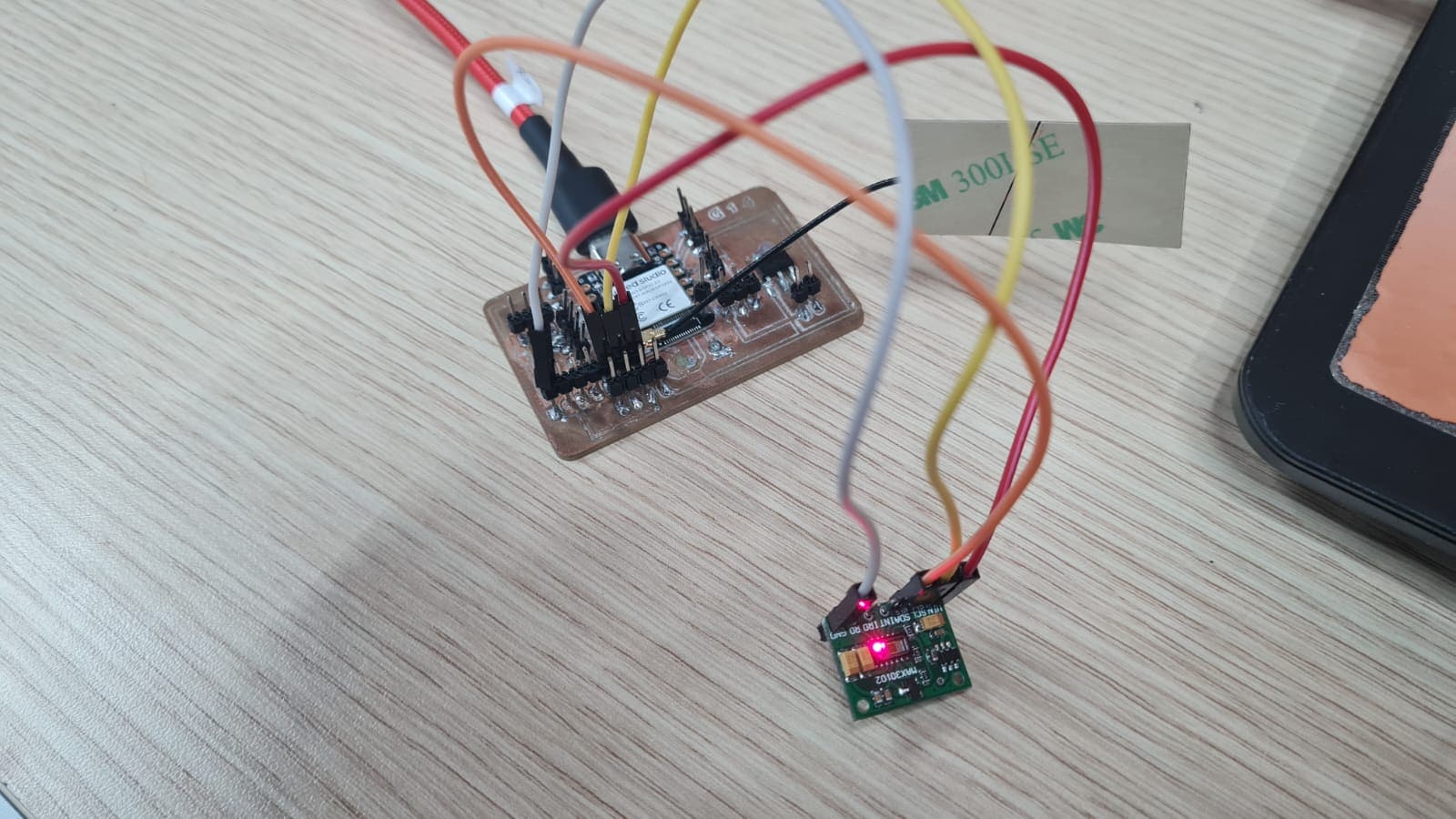
After verifying some information about the Max3102 sensor and as my next part of the assignment, I wire it to the circuit board I design a few weeks ago. For this part i'm going to need 4 wires and connect them to the next pins:
is the perfect environment for makers, students, and researchers interested in testing, learning or teaching IoT. Join thousands of users from around the world in making the future data-driven. provides a secure and easy way to build IoT solutions for students, makers and researchers. It is used for sending data from any Internet-enabled device to the cloud, triggering actions and alerts based on that data, and visualizing it.

Features:
Data from: Ubidots
is an OASIS standard messaging protocol for the Internet of Things (IoT). It is designed as an extremely lightweight publish/subscribe messaging transport that is ideal for connecting remote devices with a small code footprint and minimal network bandwidth. MQTT today is used in a wide variety of industries, such as automotive, manufacturing, telecommunications, oil and gas, etc.
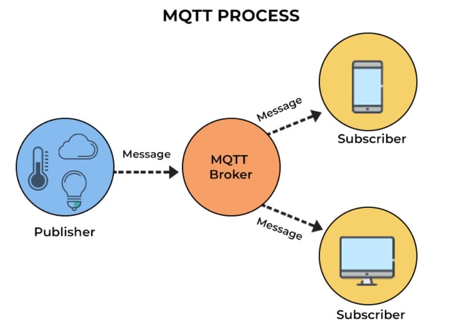
Features:
Data from: MQTT
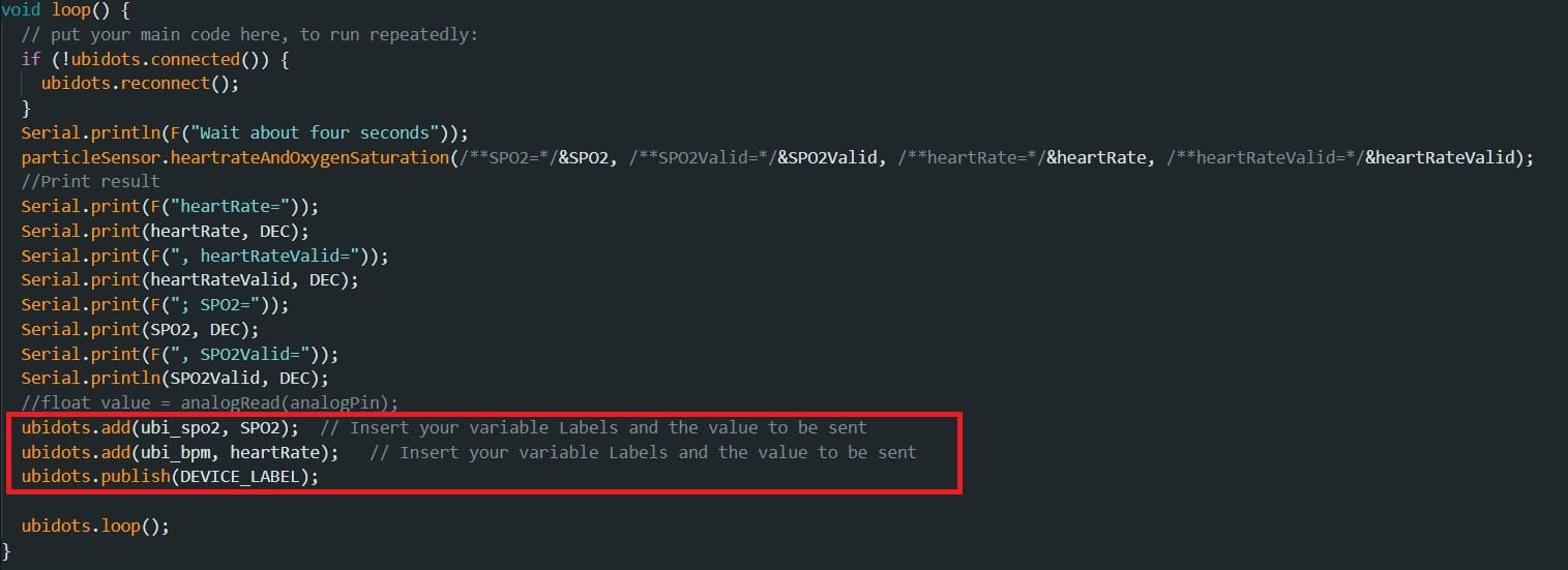
In this part i'll show the connection of my device using MQTT protocol. I'm going to show the code I'm using and explain it:
Lets begin:


In this next section I'm sharing with you some 3 videos I took of the final result. En each video you can see the measurements of the max30102 sensor in real time . With this now I can monitor the results of the measurements just by having the the link yo my dashboard.
So far i've try to detail as much as I can for my final project. So, in this part i'm listing the libraries i'm using or that ones that for now i'm considering.