Week 3: Computer-Controlled Cutting
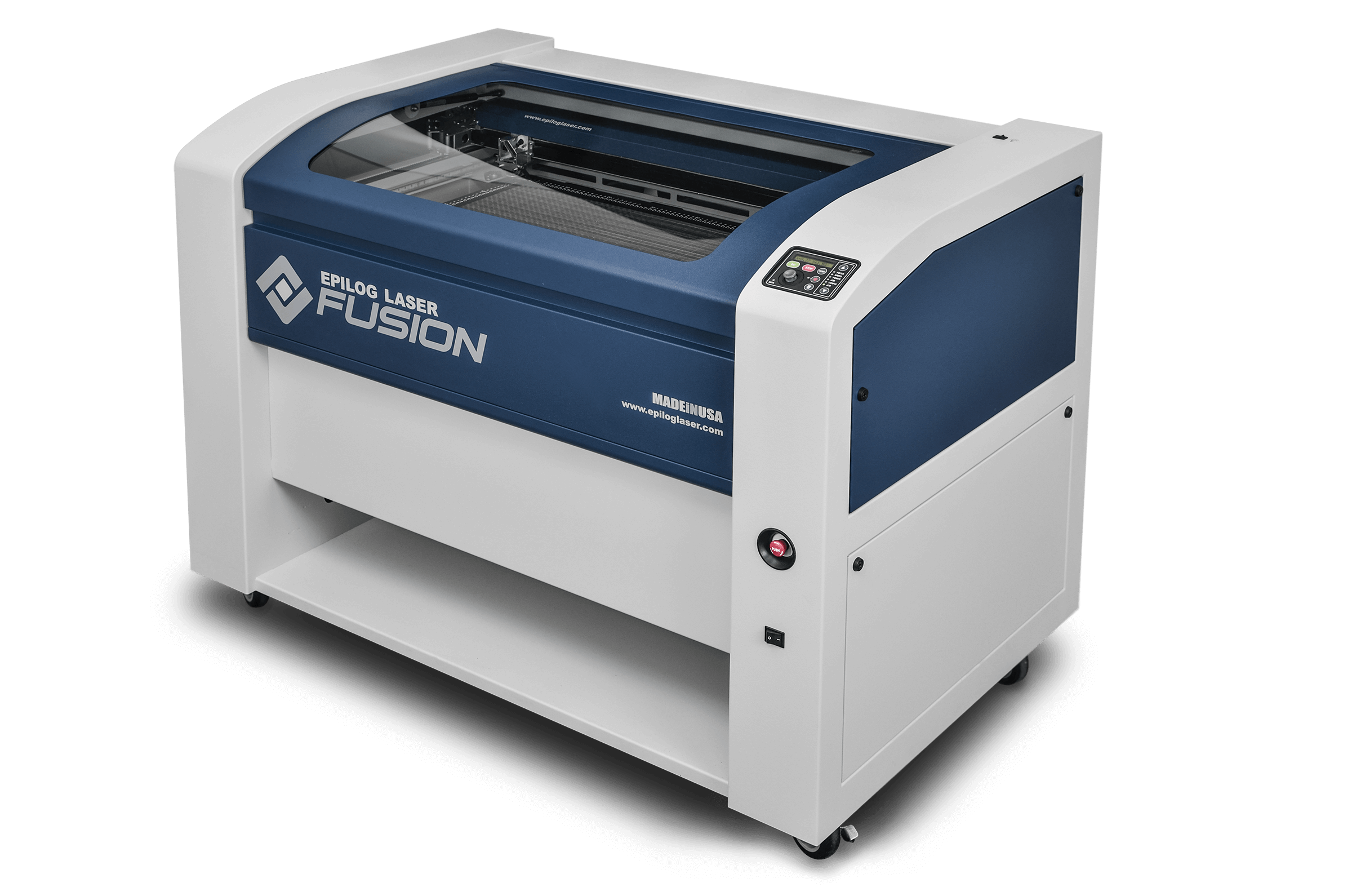
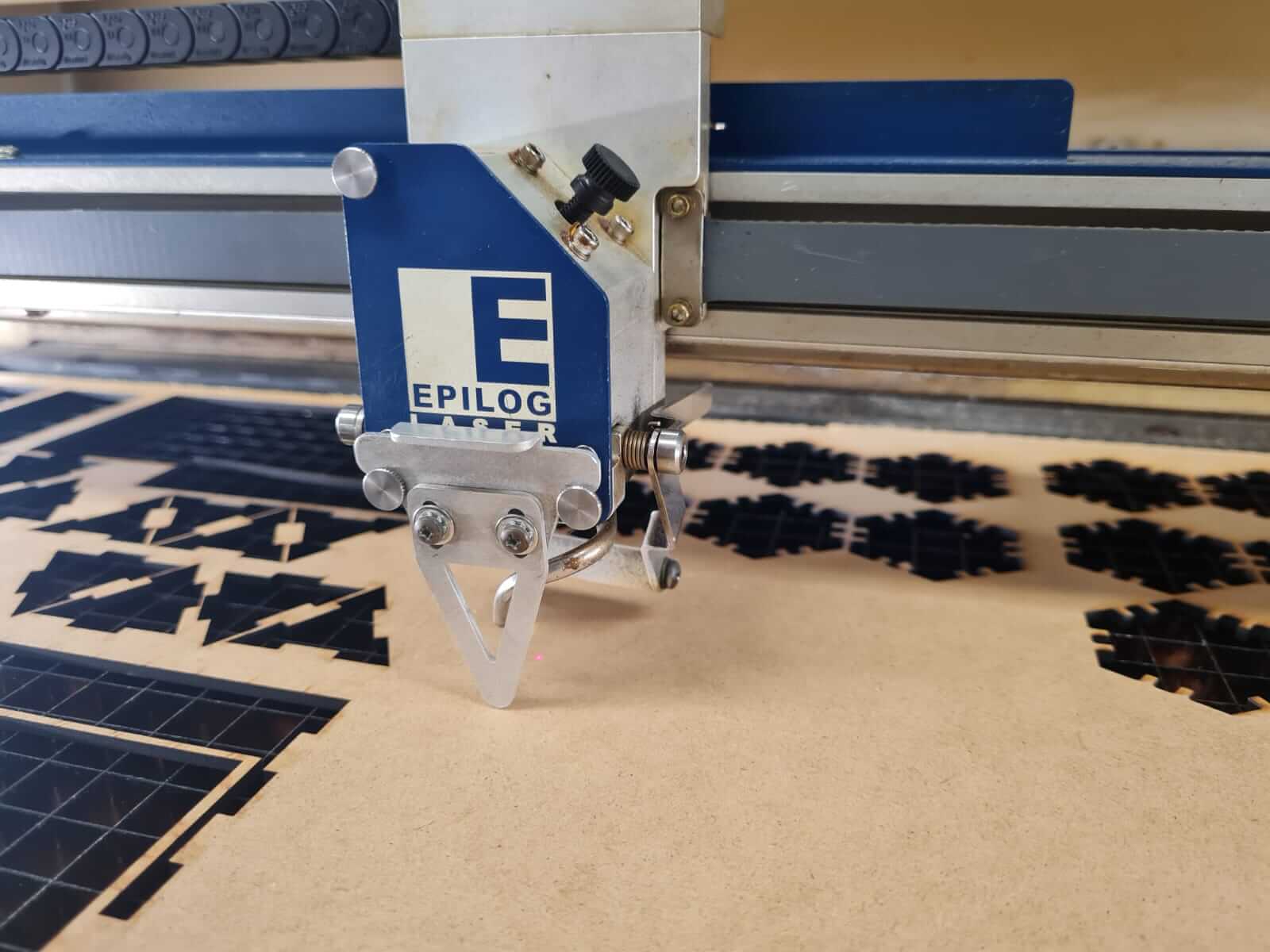
This week, I learned how to generate a vectorized drawing in Inventor Professional, export it to Adobe Illustrator for use with the Epilog M2 30W CO2 laser. The assignment is to make a construction kit made of a parametric design. The material used was 3mm thick MDF. The Co2 laser has a maximum power of 30W as it is specialized in engraving. However, it can be used to cut MDF or Acrylic up to 4mm deep in a single pass. The Epilog M2 has a work area of 1000mm x 700mm
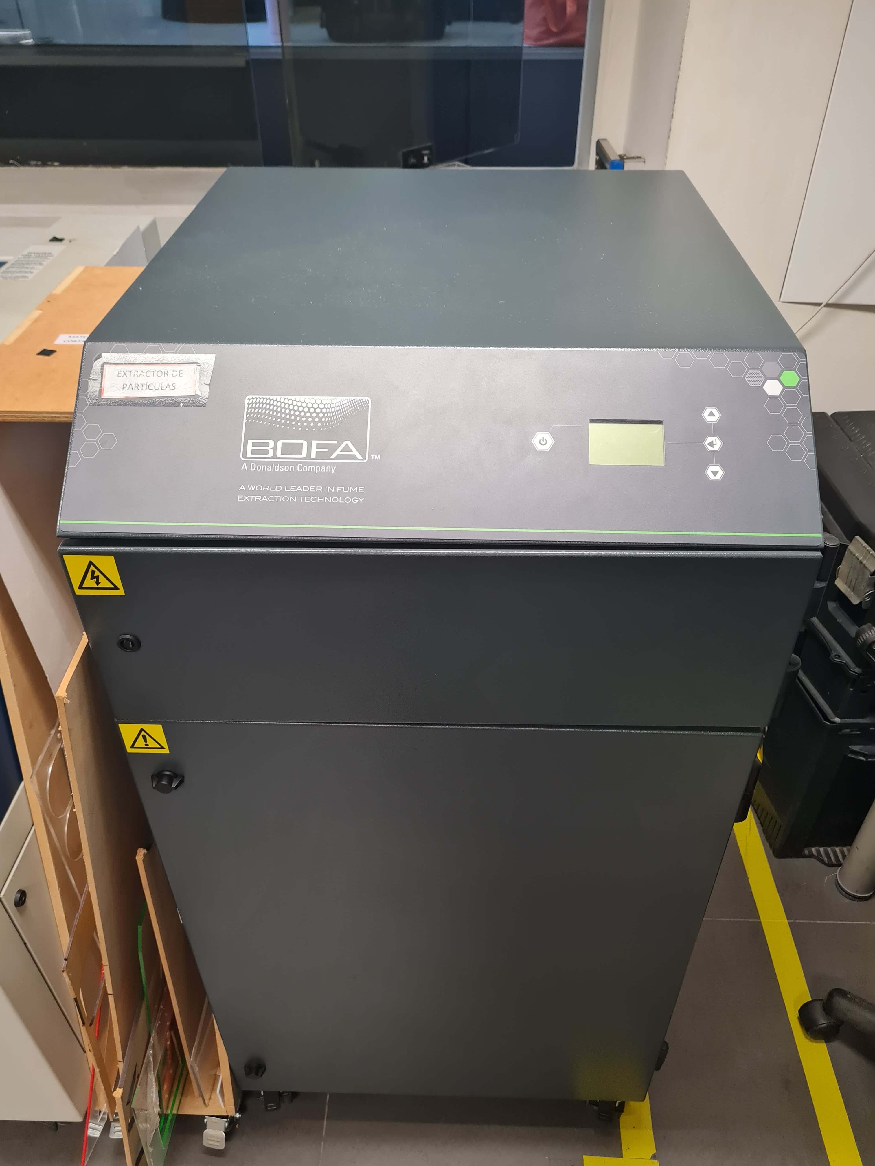
The first step is ensuring that the compressed air valve and pressure regulator is switched on and working at 2 Bar or 30 PSI, also that the BOFA filtration system is connected and functioning correctly. This is crucial for maintaining the proper operating conditions of the laser cutter and ensuring effective extraction of fumes and particulates generated during the cutting or engraving process.
.jpg)
With the BOFA filtration system connected and functioning correctly, you can be assured of efficient fume extraction and a clean working environment. In addition, proper ventilation and filtration not only contribute to the quality of the final output but also help maintain a safe and healthy working environment for operators. Once these foundational steps are in place, the subsequent setup and operation of the laser cutter can proceed smoothly and efficiently. Now, you can proceed with confidence to the next steps of setting up and using the laser cutter for your projects.
Next in line is the Focus Calibration, a crucial step that varies depending on the thickness of the material being used. To efficiently calibrate the Z-offset, a focusing tool is placed on the toolhead. All calibrations are conducted through visual inspections to streamline the machine setup process and minimize time investment. This calibration ensures precise laser focus, which is essential for achieving optimal cutting and engraving results. As a general rule, conducting visual inspections of the lenses after every few hours of cutting or upon observing any decline in cutting quality is recommended. If any residue or debris is detected on the lenses during inspection, it indicates that cleaning is necessary. This proactive approach helps maintain optimal cutting performance and preserves the longevity of the toolhead.
It is advisable to inspect the platform of the CO2 laser and eliminate any residual components that could compromise the flatness of the working material.
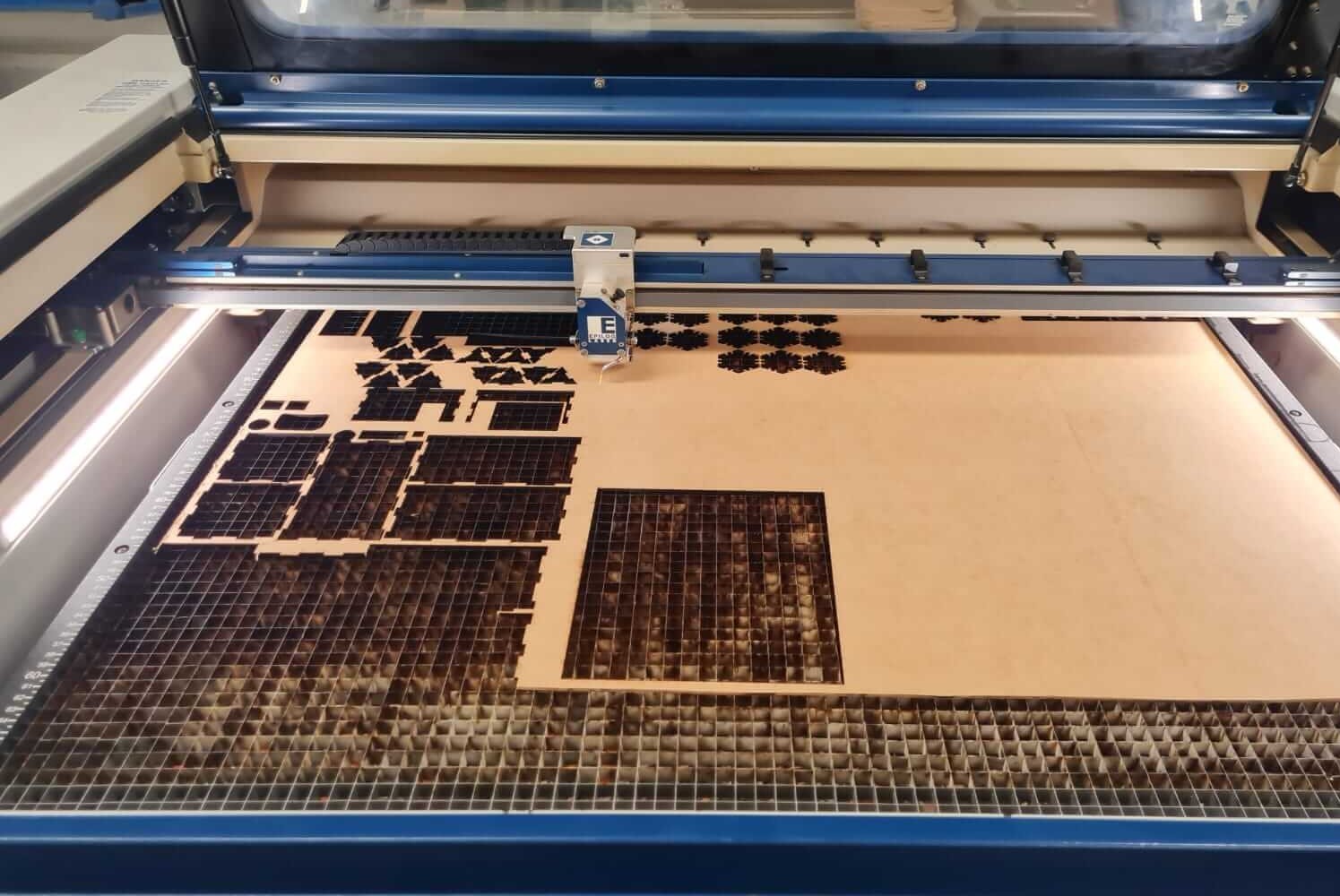
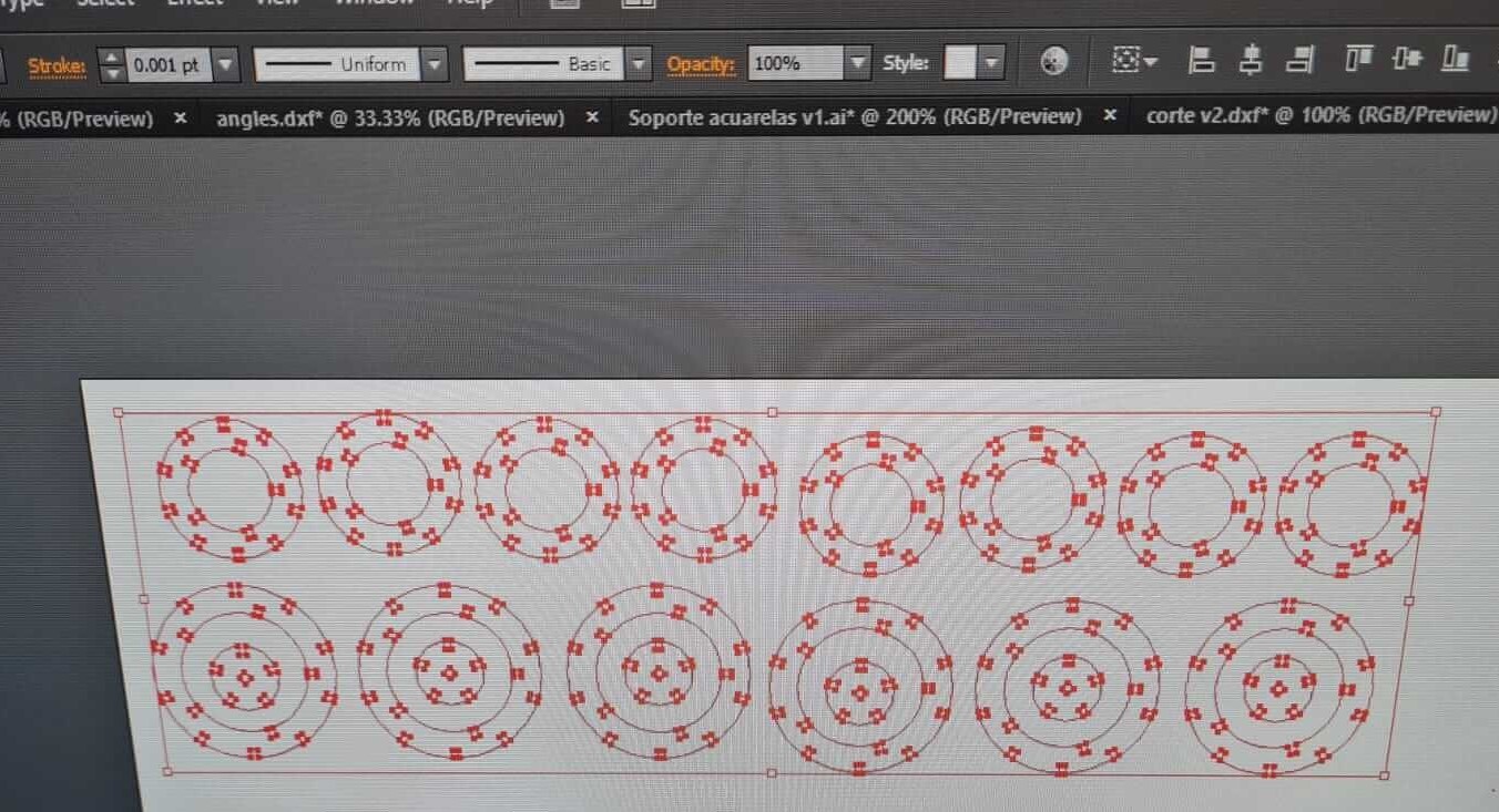
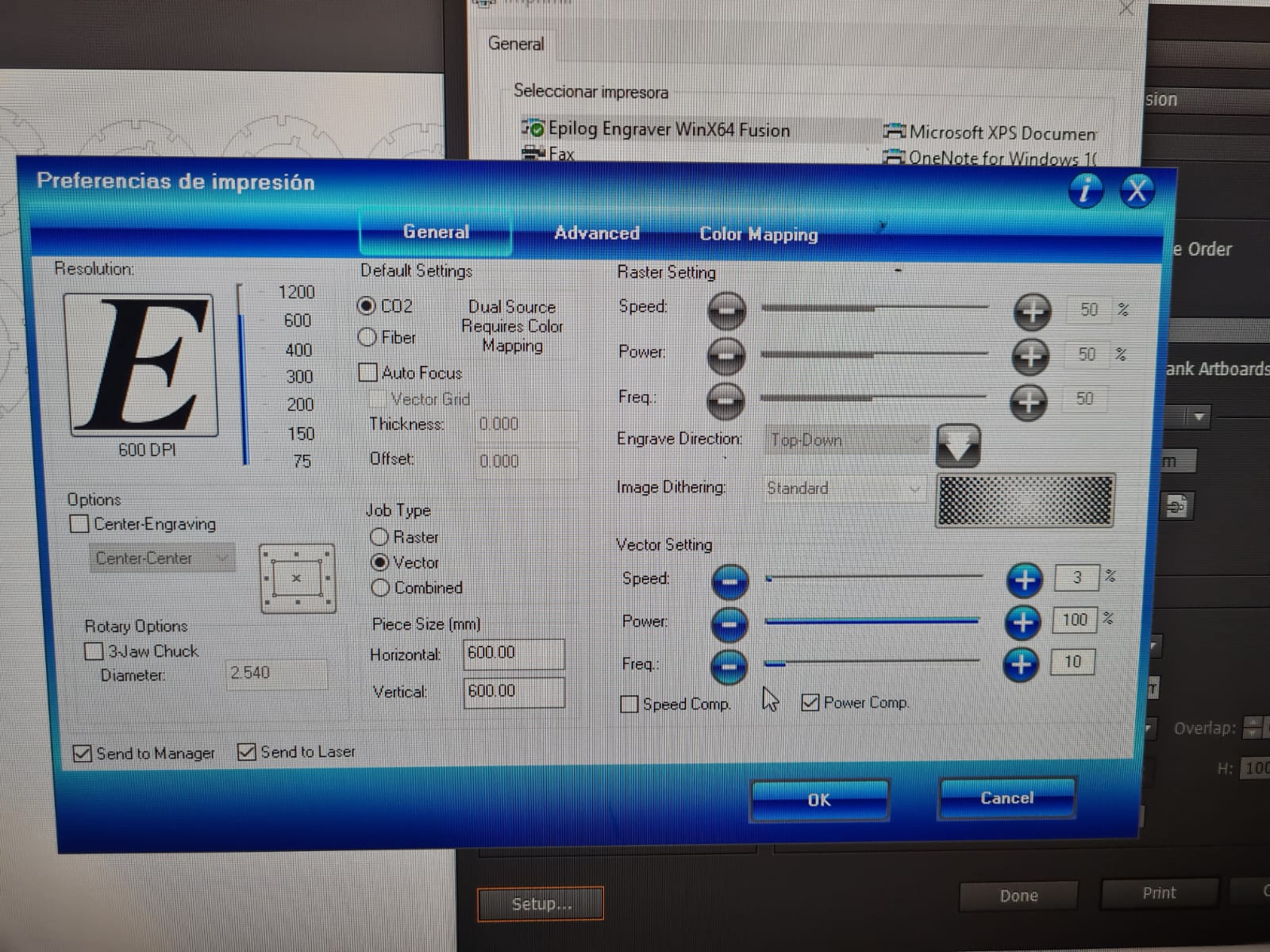
In this step, line thicknesses need to be assigned to vectors in Illustrator. A line width of 0.001 pt corresponds to a vector cut, while a greater line width is considered rasterized and processed as an image. Therefore, vectors can be separated into layers to combine vectorization and rasterization in a single project. Additionally, printing parameters can be adjusted based on the color of the vector line (Color Mapping). This allows for the use of different power settings depending on the line color. Another useful function is prioritizing different types of passes for convenience and to improve surface finish. As a bonus, I think that optimizing space during the setup of cutting pieces is very beneficial. By minimizing material waste, not only are resources saved, but costs and environmental impact associated with production are also reduced. Note that the picture is without space optimization.
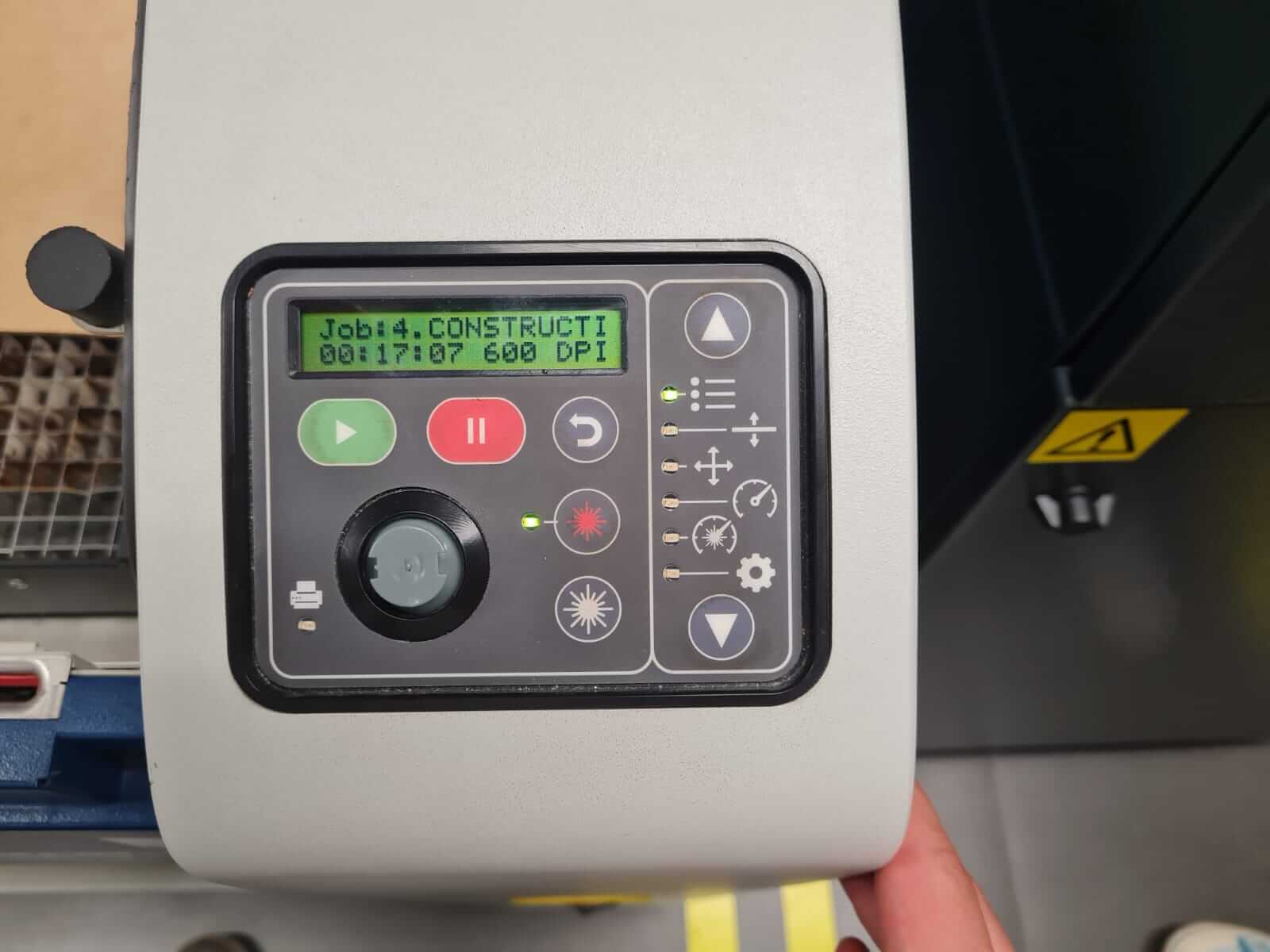
During this step, it is important to review the manufacturer's recommended parameters for the specific type of material intended for use. Experimenting with various parameters is advised to gain a deeper understanding of their impact on the resulting output. This iterative process allows for optimization of settings to achieve desired cutting or engraving outcomes efficiently and effectively.
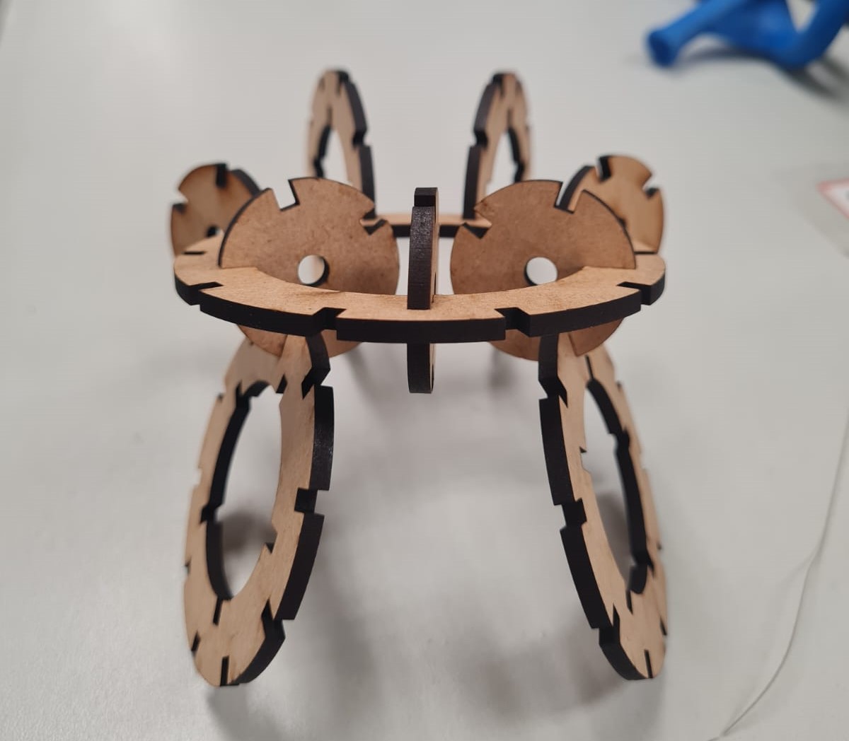
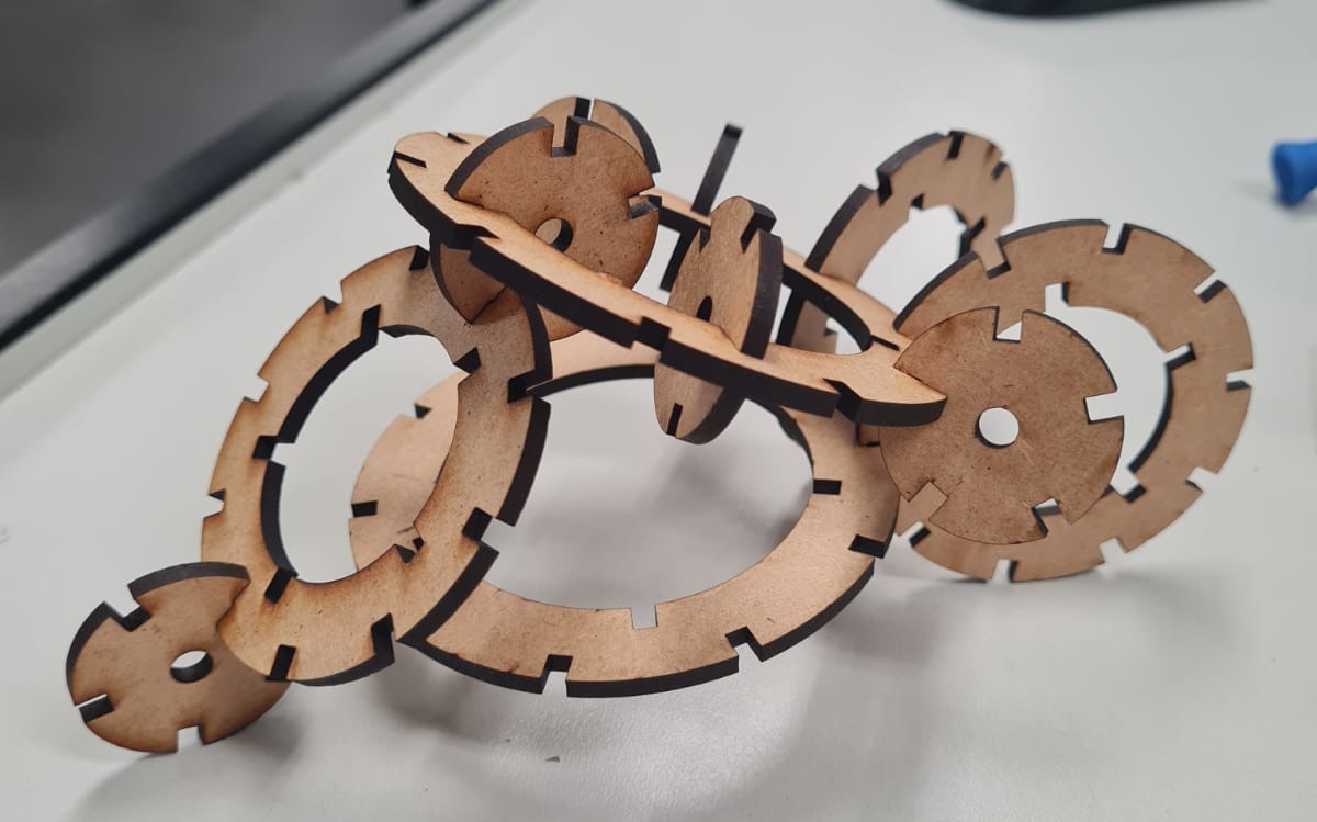
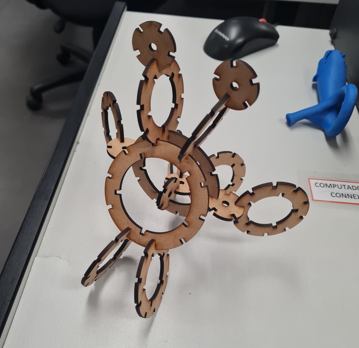
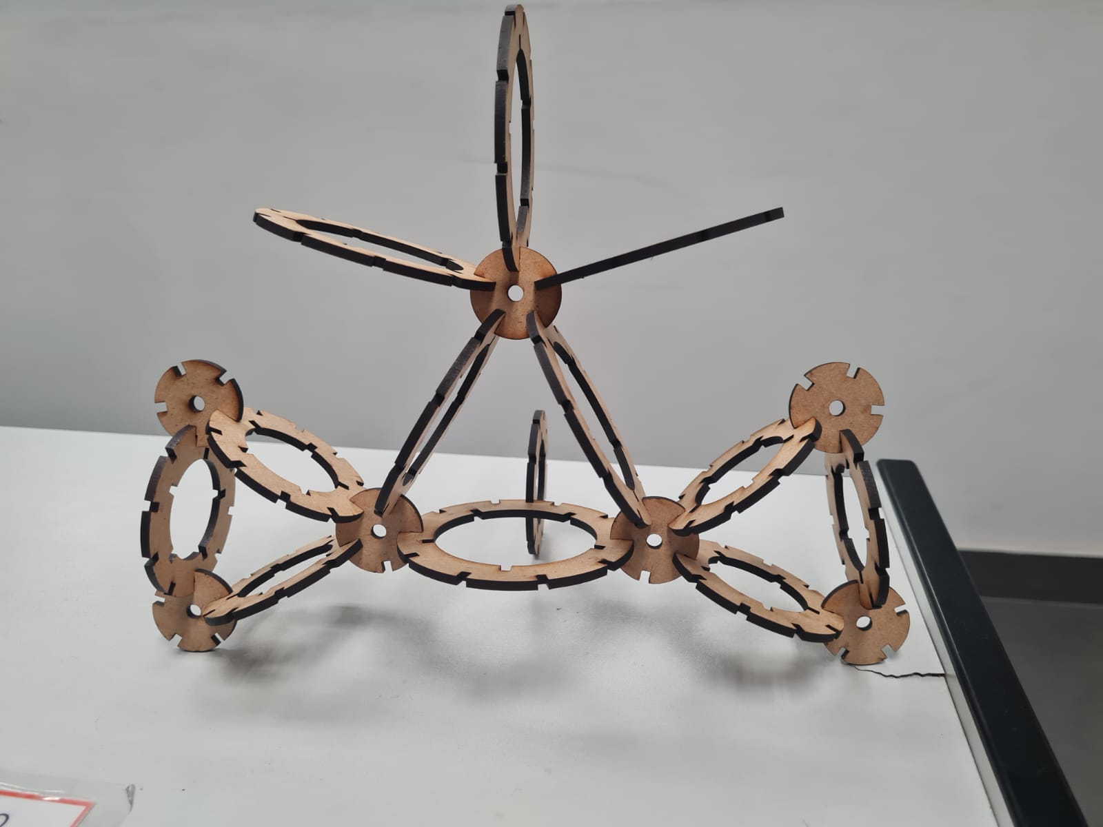
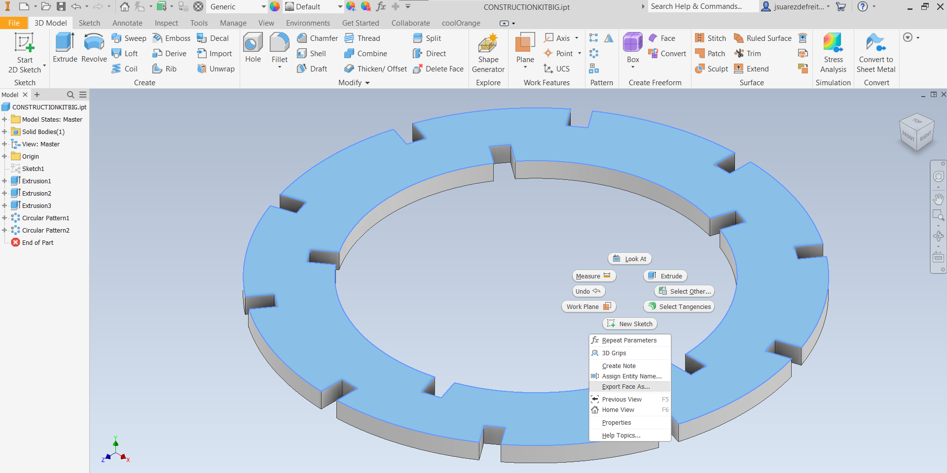
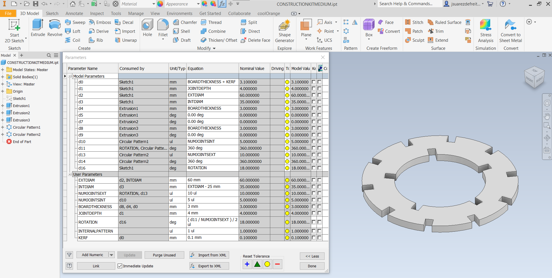
The design is fully parametric, which means the same model can create different variations of the piece by simply editing user parameters. For this assignment, the goal is to develop a parametric model that includes board thickness and kerf adjustments, enabling the design to accommodate various types of materials and thicknesses. I aim for this parametric design to generate all the necessary pieces for the kit. The objective is to use a single file to produce multiple pieces, resulting in a nice construction kit.
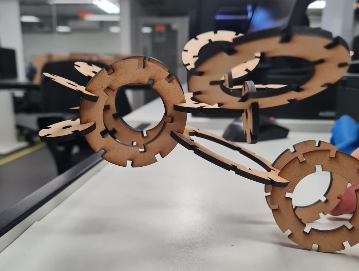
The chosen material for the construction kit is 3mm thickness MDF. Initially, based on this week's group assignment, Ernesto Buendia calculated a kerf value of 0.2mm from a simple test for this specific material. However, during testing with a 0.2mm kerf tolerance, some pieces were too loose, affecting the assembly, while others fit perfectly. This discrepancy arose because the 3mm MDF was not perfectly flat and exhibited significant variations in thickness. To resolve this issue, I adjusted the kerf tolerance to 0.1mm for my kit, ensuring a more consistent and precise fit during assembly.
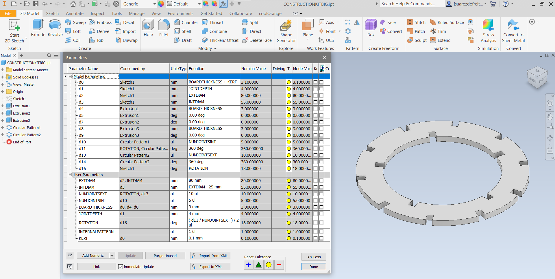

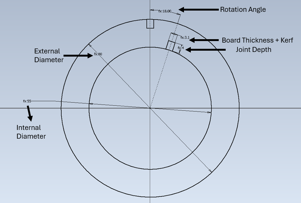
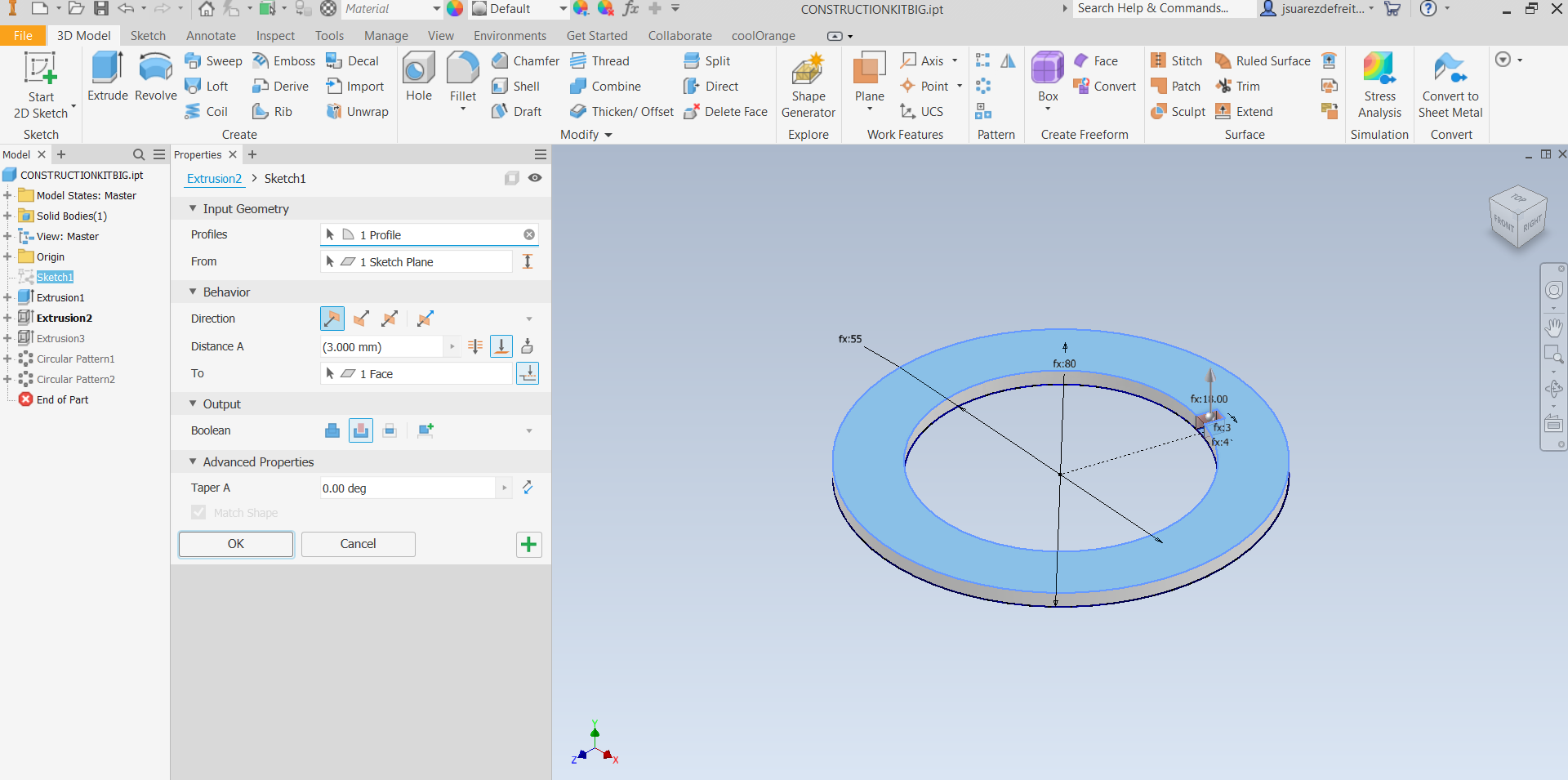
The design parameters are used in the principal 2D Sketch for defining the dimentions of the 3D Model. In this Sketch the parameters used are: External Diameter (80mm)//Internal Diameter (55mm)//Joint Depth (4mm)//Rotation Angle (∠18°Deg)//Internal Pattern (1ul)//Board Thickness (3mm)//Kerf (0.1mm).
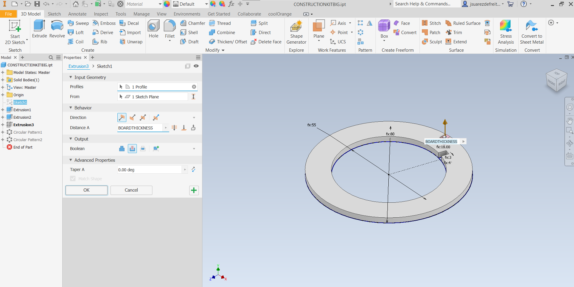
In this step I extruded the disk to the Board Thickness.
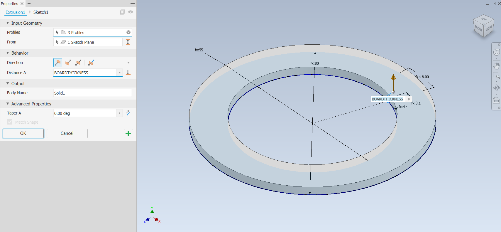
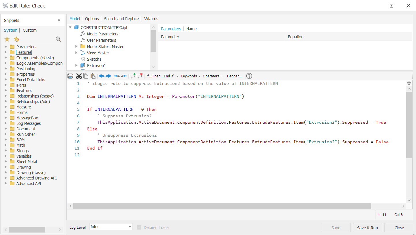
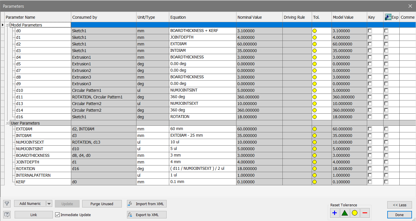
Extrusion operations are crucial for both internal and external joints in the model. For external joints, the extrude distance is set equal to the board thickness. However, handling internal joints involves using the "INTERNAL PATTERN" parameter. Setting this parameter to 0 was intended to indicate that no internal pattern should be generated. However, this caused errors in Autodesk Inventor because the value 0 was considered invalid in this context. As a result, the internal pattern operation was not executed as intended, leading to errors.
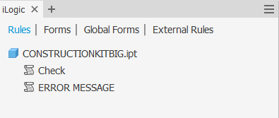
To resolve this issue, a conditional check was implemented to determine whether an internal pattern should be generated based on the "INTERNALPATTERN" parameter. When "INTERNALPATTERN" is set to 1, an internal pattern is generated. If set to 0, no internal pattern is generated, and accordingly, the extrusion operation and circular pattern are suppressed. This approach ensures that the correct features are created based on the specified parameter values and prevents errors.
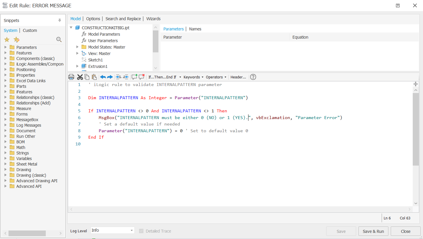
Additionally, an iLogic rule was implemented to validate the "INTERNALPATTERN" parameter. If the parameter value does not correspond to 0 or 1, a message box will display the following information: INTERNALPATTERN must be either 0 (NO) or 1 (YES).
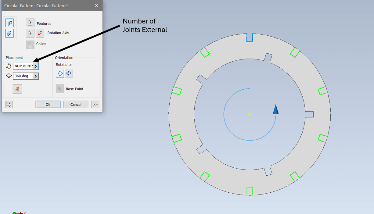
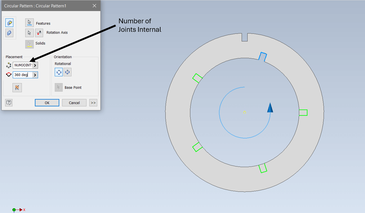
Then a Circular Pattern is used to define the number of external and internal joints as well as the placement angle.
To create all the variations for the construction kit, I had to adjust the user-parameters to achieve a desired results. This process involved changing specific parameters to ensure each variation met the necessary specifications.
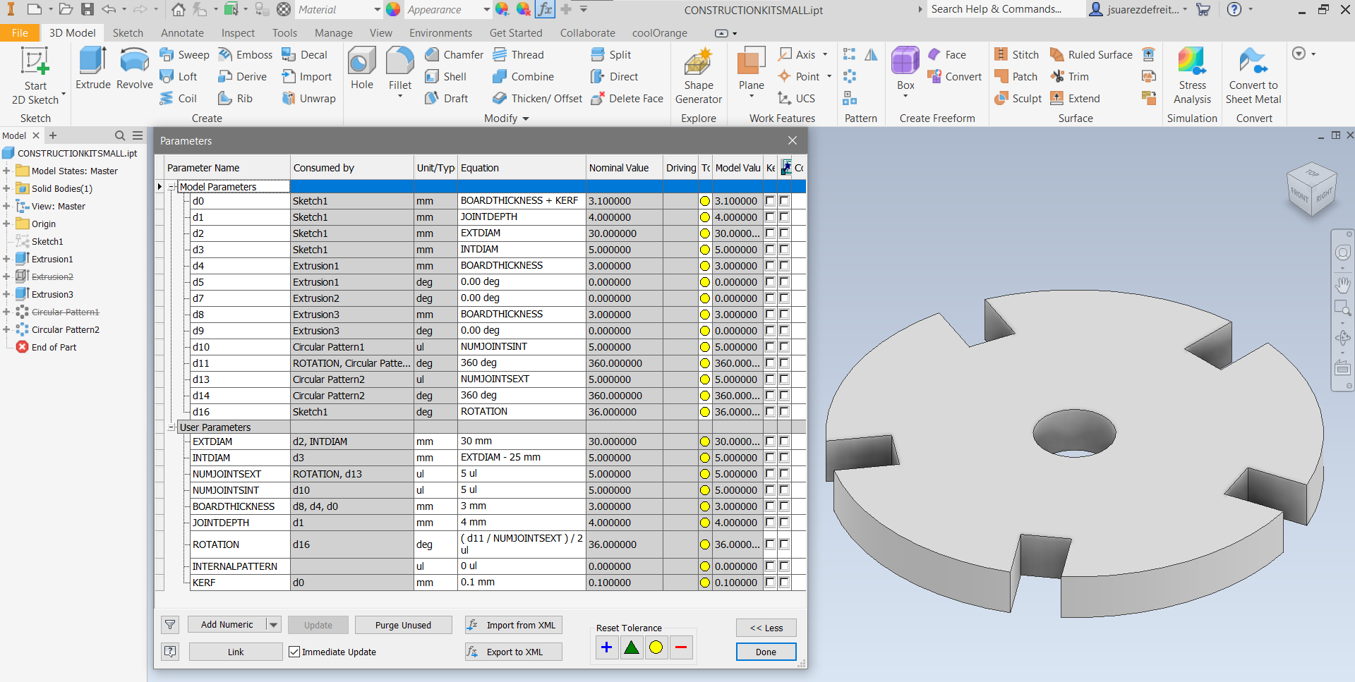

In the next video, I will demonstrate the versatility of parametric modeling by experimenting with different values for all previously explained parameters. This will showcase the capabilities of parametric design, allowing infinite combinations from a single model.
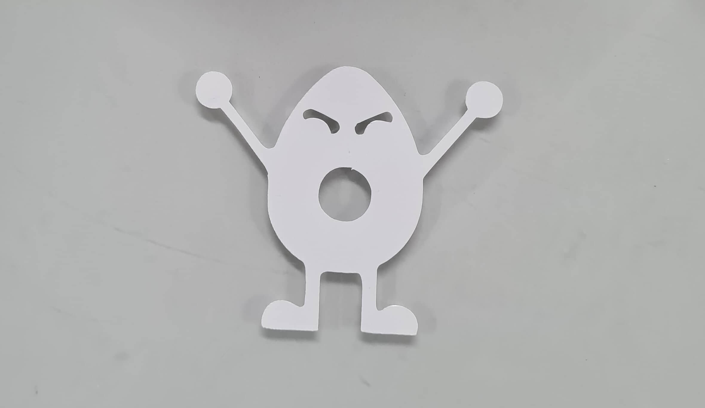
For this task, I utilized Inventor Professional to design the vectors, and then employed the Silhouette Studio software to finalize the job using the vinyl cutter.
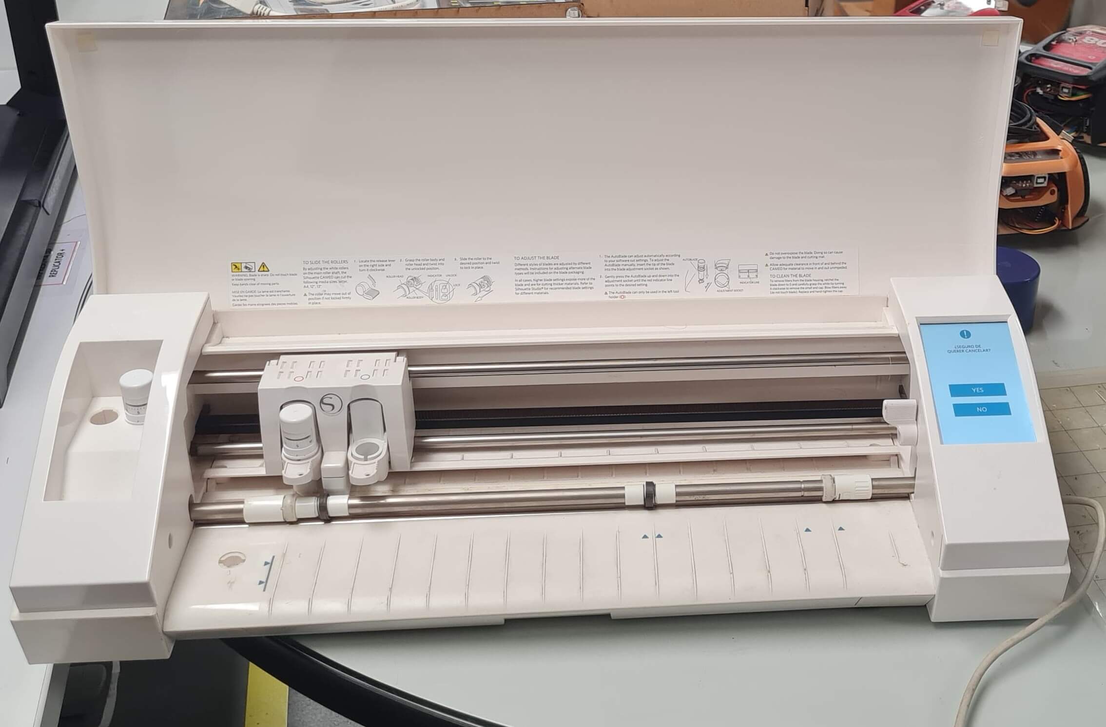
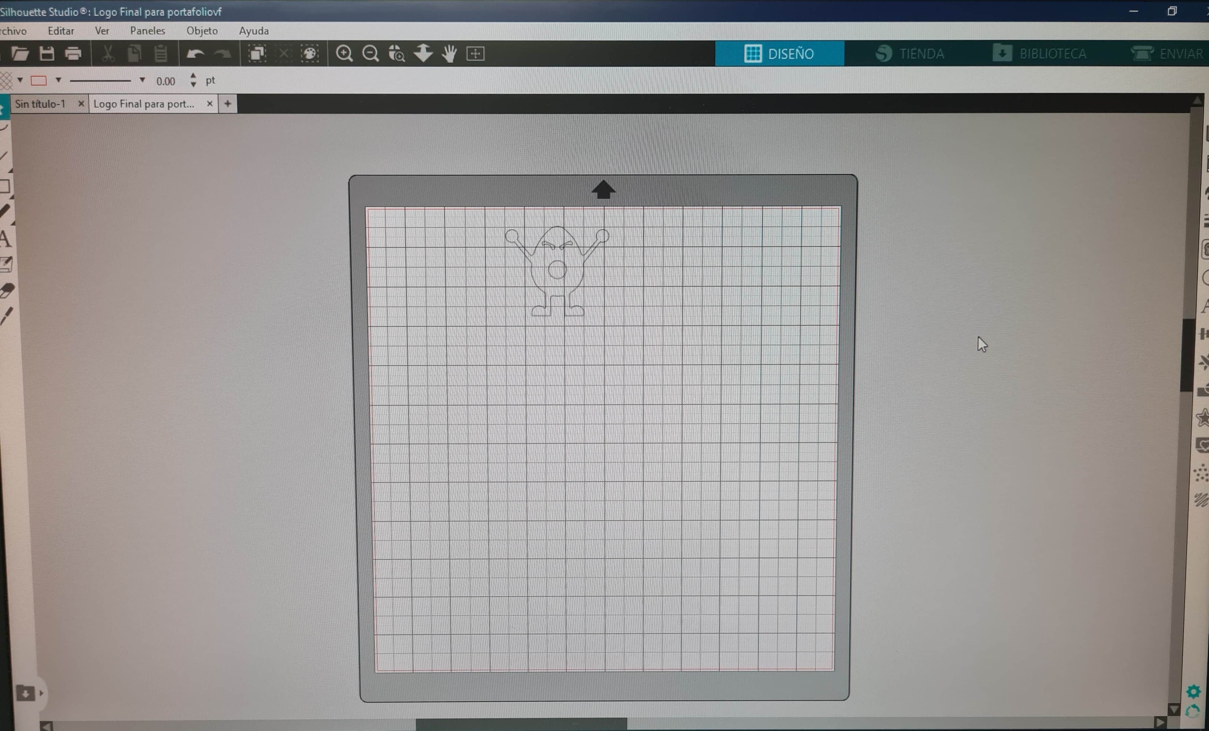
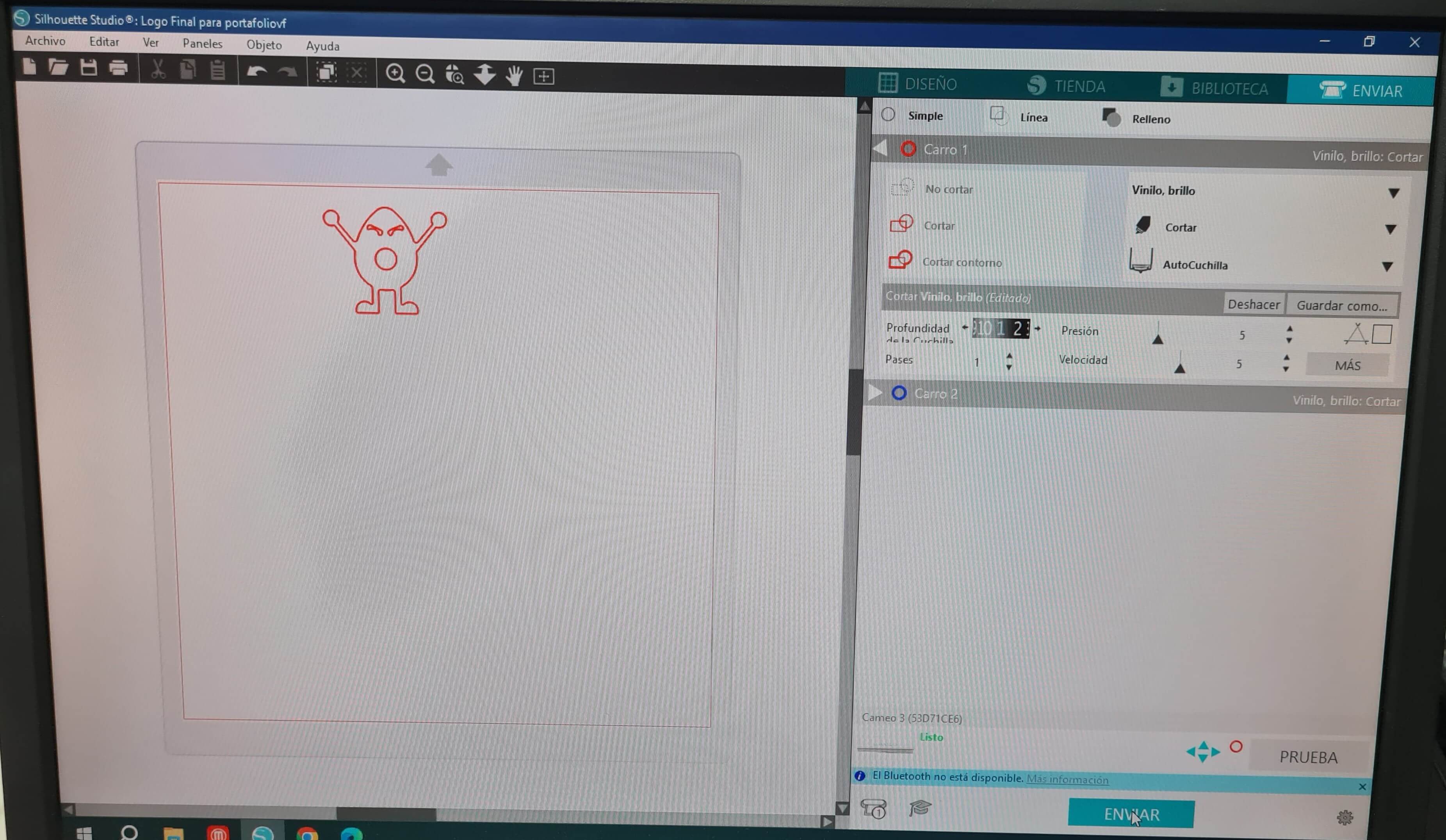
In the Silhouette Studio UI, I adjusted the parameters to achieve optimal calibration for the type of vinyl available in the FabLab. Using a sticky spray, I securely mounted the vinyl onto the Silhouette bed. Following this, I calibrated the tool depth, pressure, number of passes, and cutting speed to ensure precise and accurate cutting.
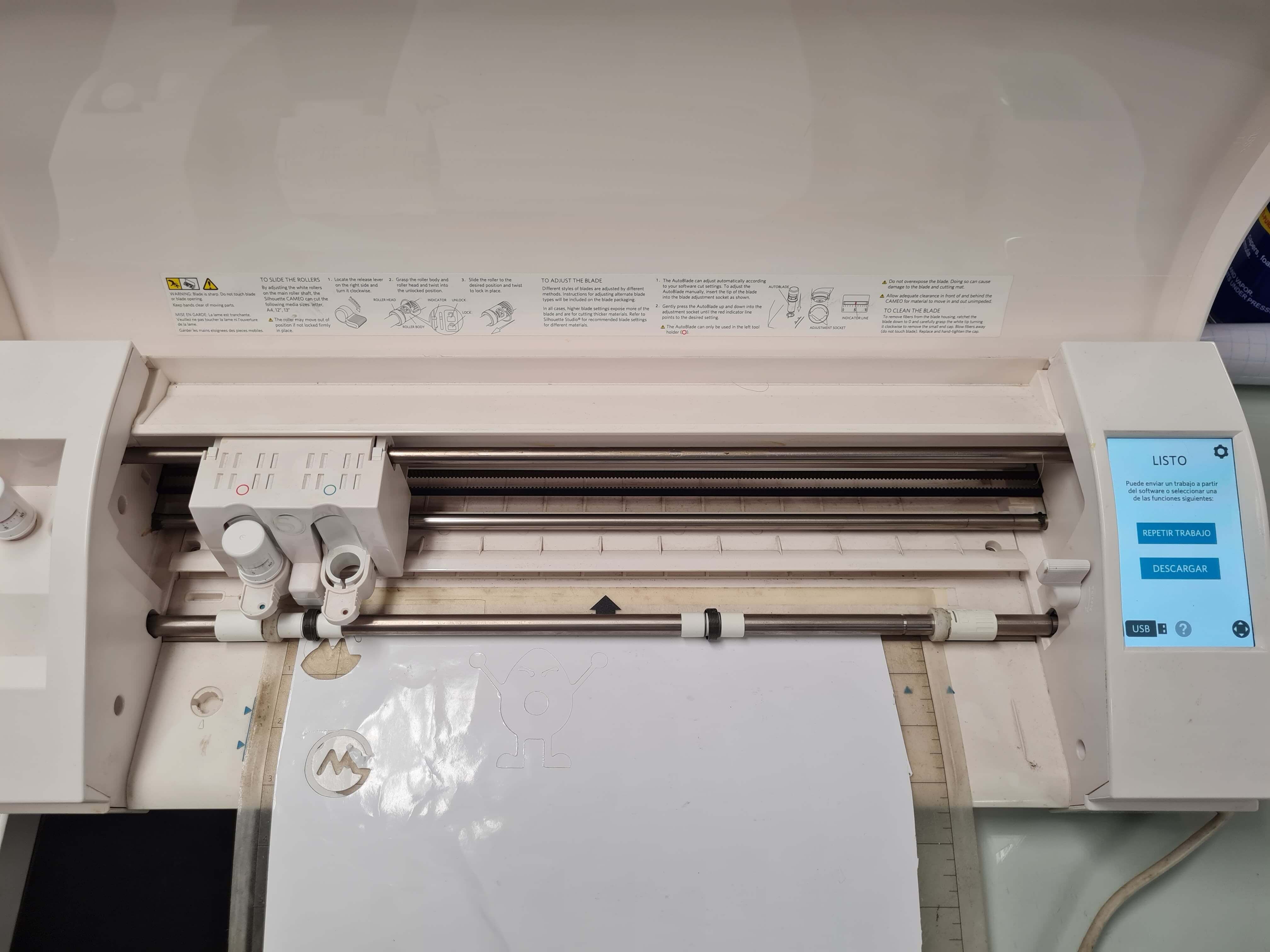
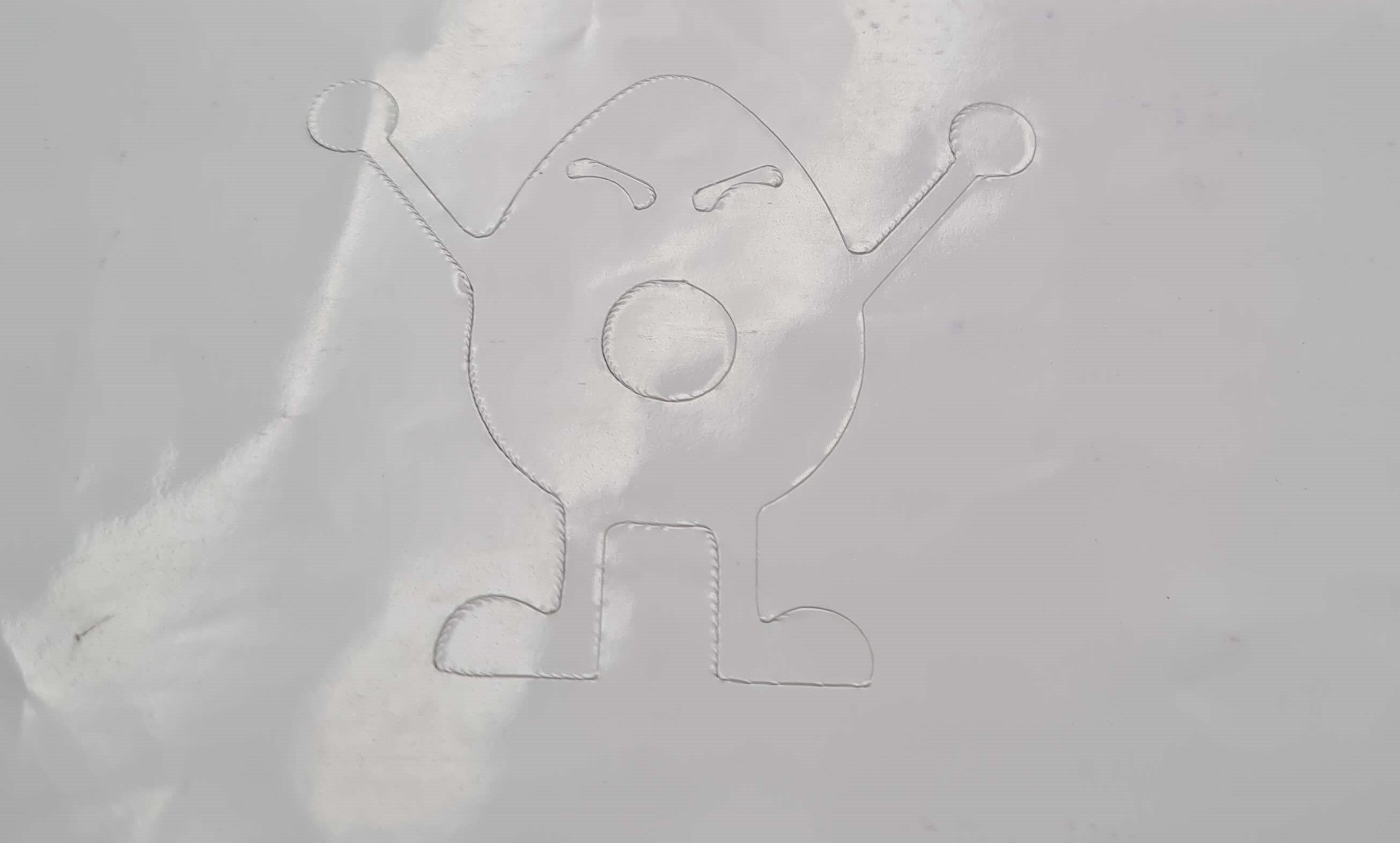
The results after cutting were excellent. The blade didn't penetrate into the Silhouette bed, and the vinyl cuts were very clean. I was very happy with the result!!
I used transfer paper to easily remove the vinyl designs from the Silhouette bed!

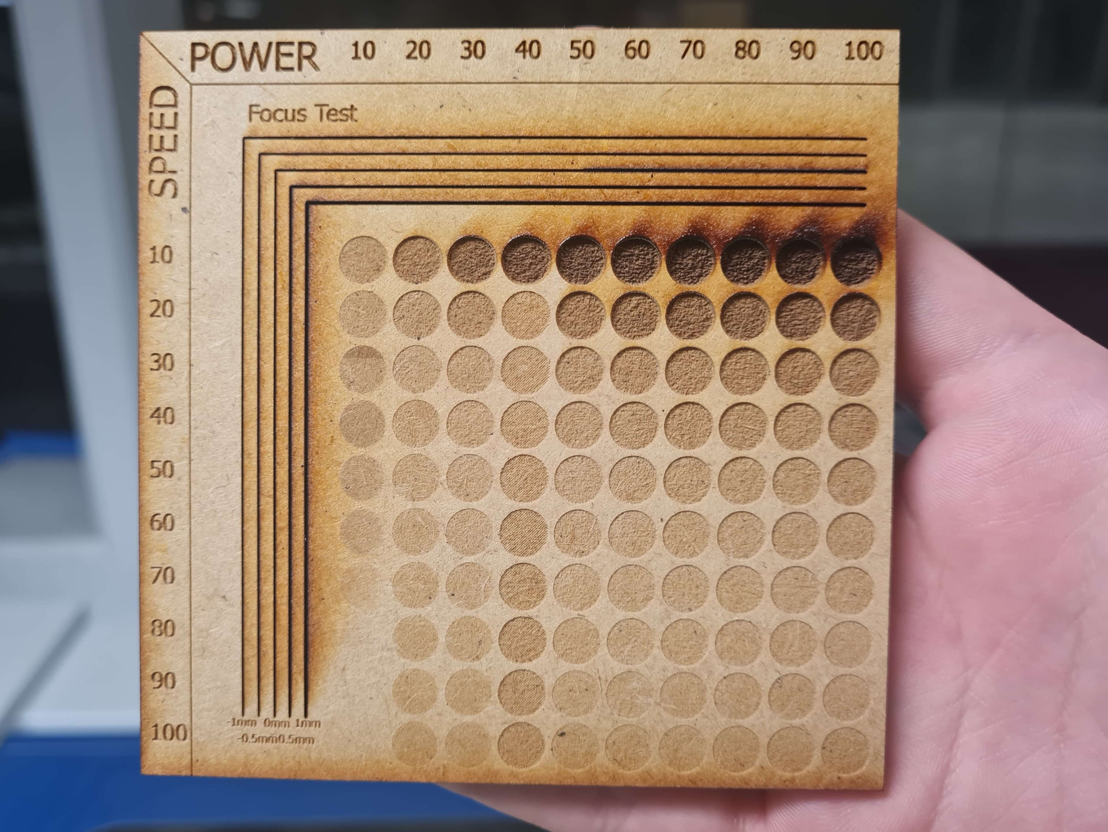
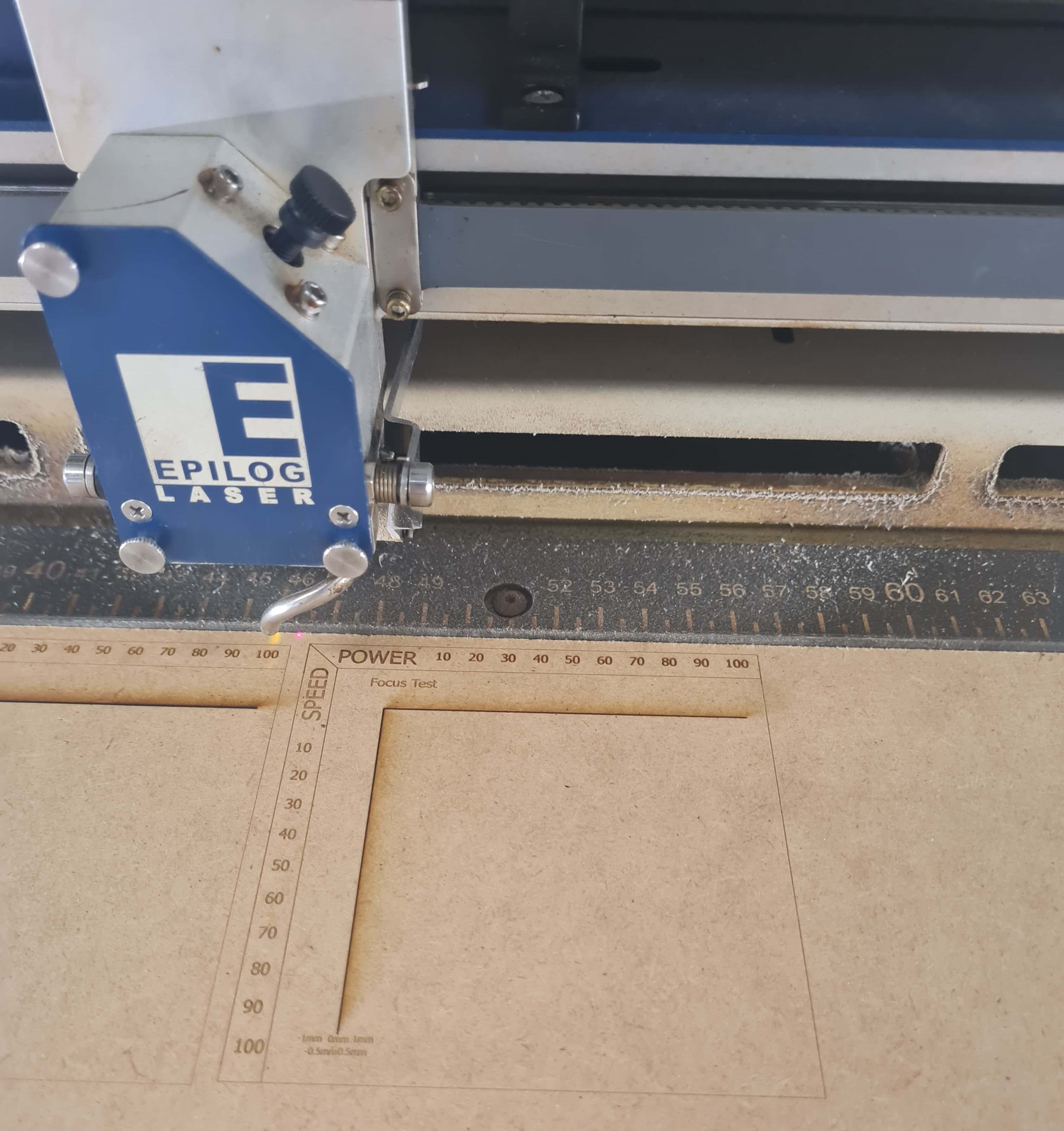
I was responsible for managing the Power/Speed settings and conducting the optimal laser focus test. To facilitate this process, I designed a simple yet effective test using Inventor Professional.
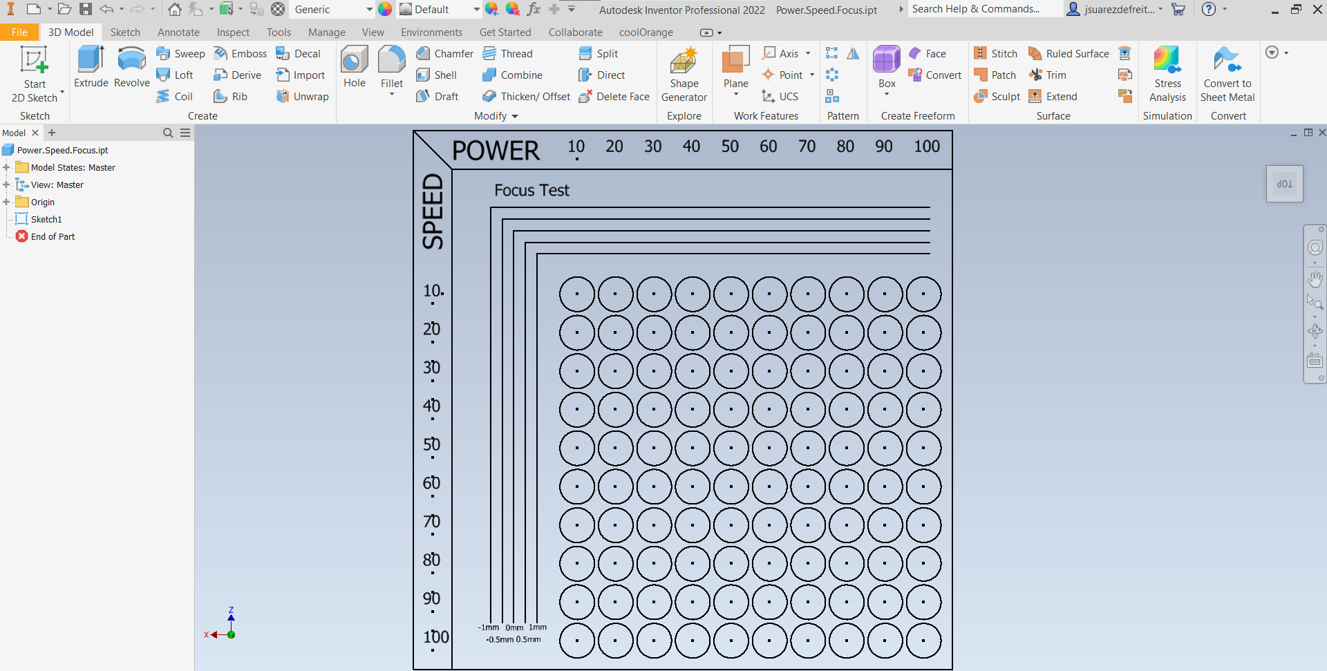
For this task, I utilized a function in the laser software called Color Mapping. This feature allows for the variation of cutting or engraving parameters by assigning different colors. Additionally, it provides a way to prioritize cutting in a specific order. This function proved to be immensely helpful. However, one limitation encountered was the maximum number of colors allowed for a job, which in this laser cutter's case, is 15. Consequently, I had to engrave in separate jobs. I opted to send the engraving by rows and adjust values for each of the 10 rows accordingly.
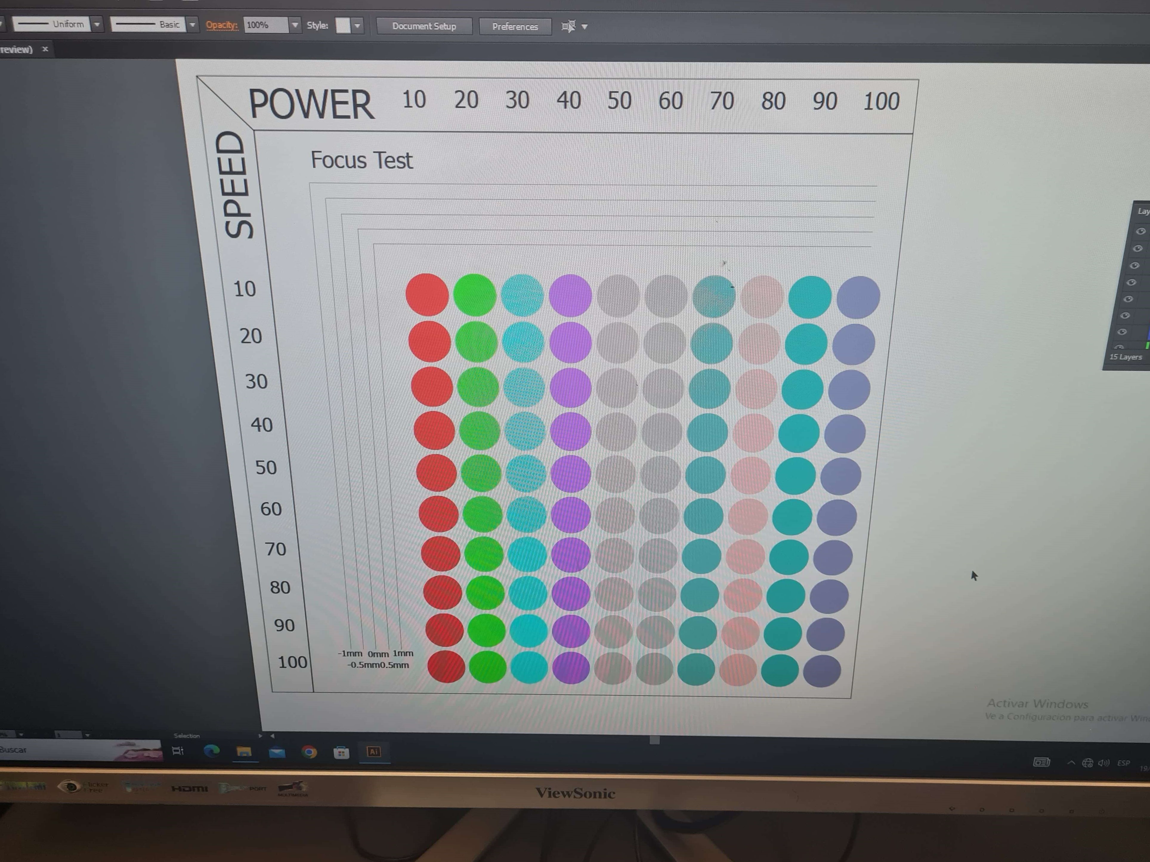
Although the results are decent, I'm not entirely comfortable because I believe I made a mistake in one of the 10 jobs to complete the engraving. Some parts do not display properly, indicating a potential error. I will repeat the process to ensure a better outcome with no errors.