Assignments
- Characterize your lasercutter's focus, power, speed, rate, kerf, joint clearance and types.
- Document your work to the group work page and reflect on your individual page what you learned.
Individual apport
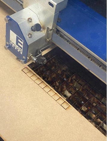
- Ernesto: My part of the group assignment was to obtain the measurement of the kerf in order to join the cut pieces in a rigid way and without room for movement. The first step was to cut ten pieces of equal size, in the image shown below each square measures 10mm per side.
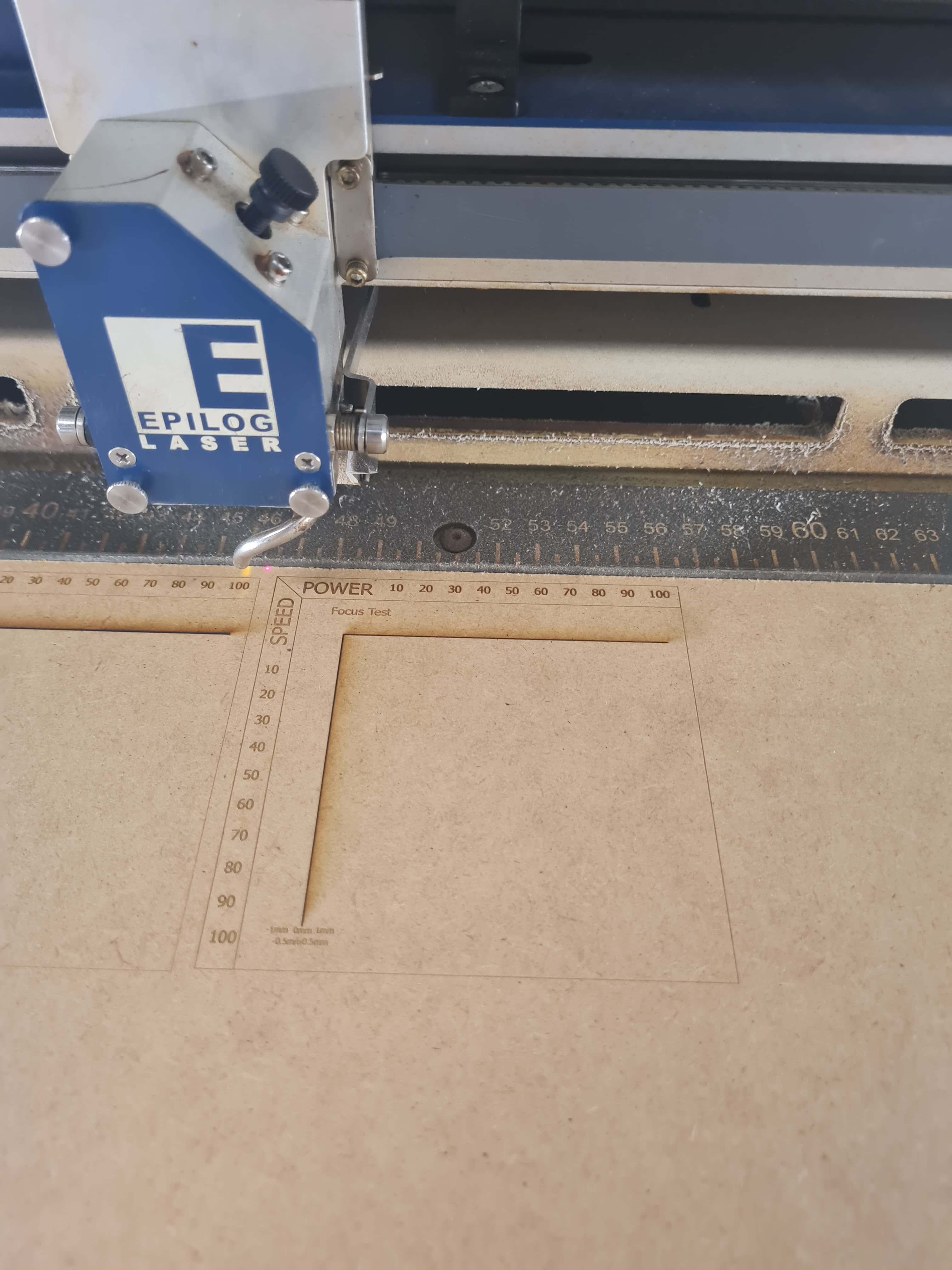
- Jorge: I was responsible for managing the Power/Speed settings and conducting the optimal laser focus test. To facilitate this process, I designed a simple yet effective test using Inventor Professional.
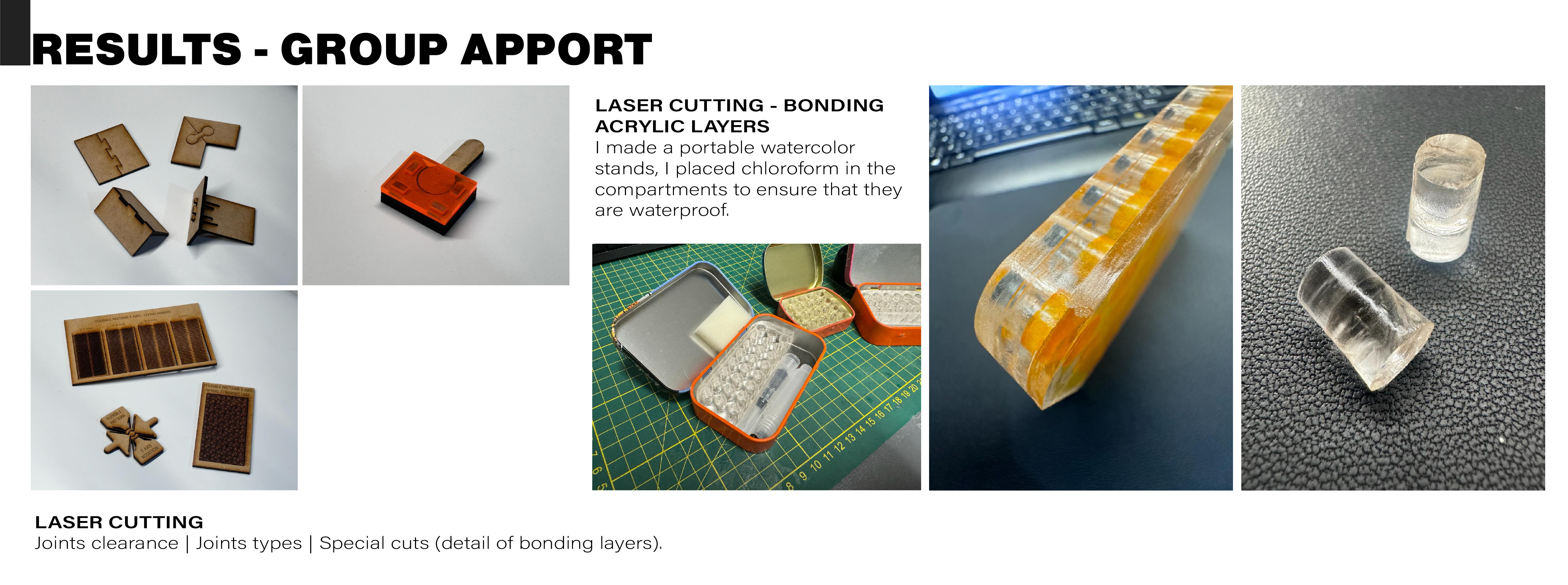
- Marcela: Clearance between joints: Tolerances. Joint types. Special cuts: flexible patterns and acrylic layer bonding.
Process
Machine parts:
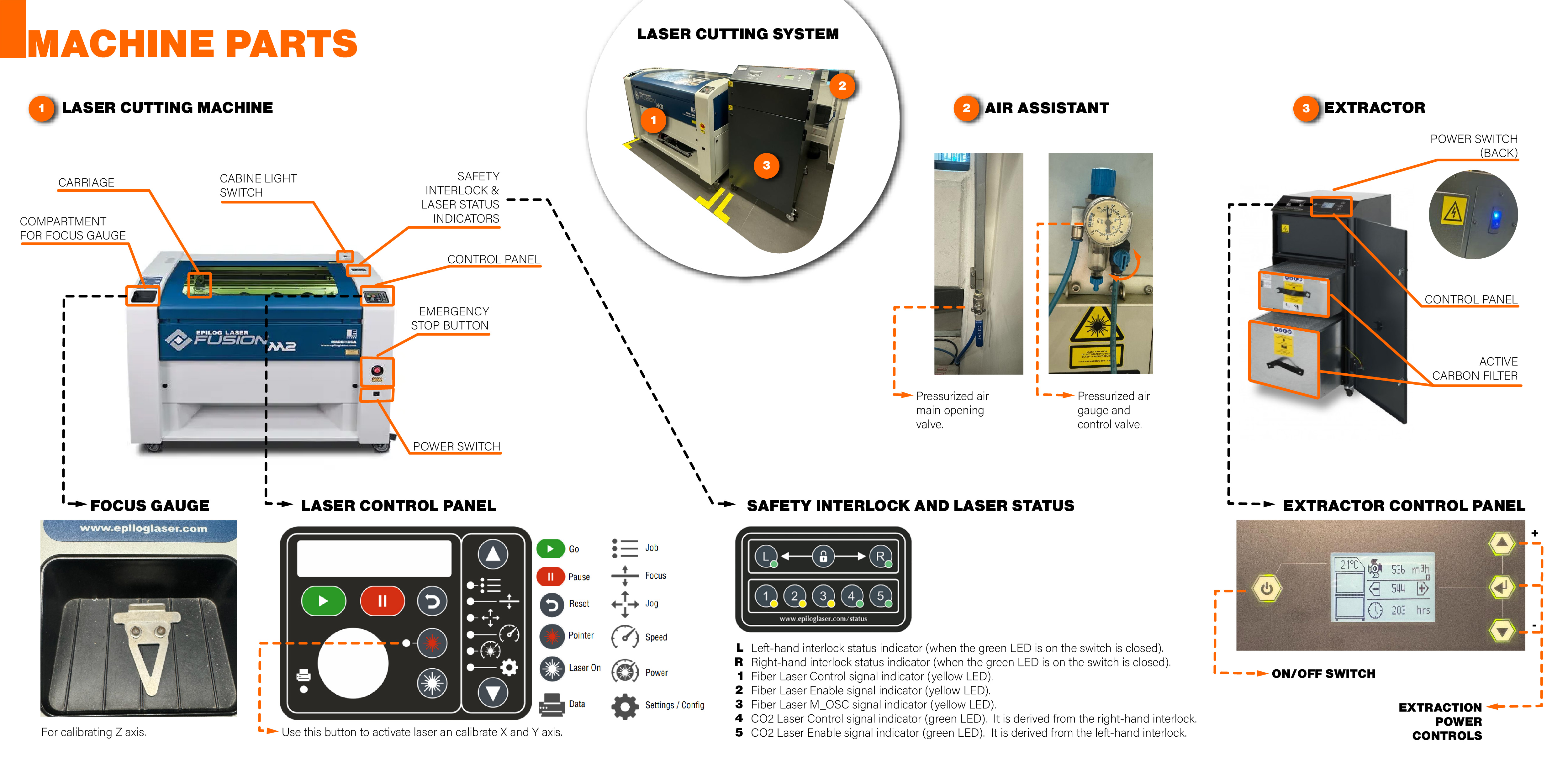
Machine start-up checklist:
- Open the air pressurized air main opening valve and make sure the air gauge reads 1 bar. You can adjust the flow by turning the control valve.
- Turn on the switch located at the back of the BOFA filter.
- Switch on the laser cutter and wait for the homing process to complete.
- Load the cutting file from the assigned computer.
- Select the file sent from the main laser cutter control panel.
- Turn on the filter and check that the flow is at 650 CFM or 310 m³/h.
- Press the start button on the control panel.
File Checklist:
- Check that there are no double lines unless you intend to repeat the cut several times (for soft materials like foam).
- Ensure that the document color is set to RGB.
- Verify that the cutting line thickness is set to "Very thin" or measures 0.005pt.
- Check that the X and Y axis positions match the chosen axis positions when sending for printing.
- You can send a preview cut with the lid raised to verify that the job fits the chosen material. Each time the lid opens, the X and Y axes move, but the laser is not active until the lid is closed again.
Calbration Checklist:
- Check the material thickness and use the recommended parameters.
- Place the material on the worktable.
- Use the control joystick to move the head to the middle of the cutting area.
- Z-axis Calibration: Use the focal distance focus gauge to adjust the height of the Z-axis. Make sure the laser is defined and has no fuzzy borders. If so, clean the lens.
- X and Y-axis Calibration: Use the control joystick to position the starting point. To visualize the laser, use the laser light power button.
- Ready to cut.
Machine Parameters:
Focus:
This parameter refers to the distance between the laser lens and the surface of the material. It's crucial for determining the sharpness and depth of the cut or engraving. Adjusting the focus correctly ensures that the laser concentrates its energy optimally at the desired point.
Power, Speed, and Rate:
- Power: The power of the laser determines the intensity of the energy delivered to the material. Adjusting the power is essential to achieve consistent and precise cuts or engravings on different types of materials. It's typically measured in percentage (%), where a higher value indicates more power.
- Speed: Speed refers to the rate at which the laser head moves over the material surface. Adjusting the speed affects both the quality of the finish and the efficiency of the engraving or cutting process. It's typically measured in units of length per time, such as inches per minute (in/min) or millimeters per second (mm/s).
- Rate: This parameter may refer to the pulse repetition rate of the laser, especially important in marking or deep engraving processes. It can also refer to the material feed rate in the case of machines that can cut continuous materials.
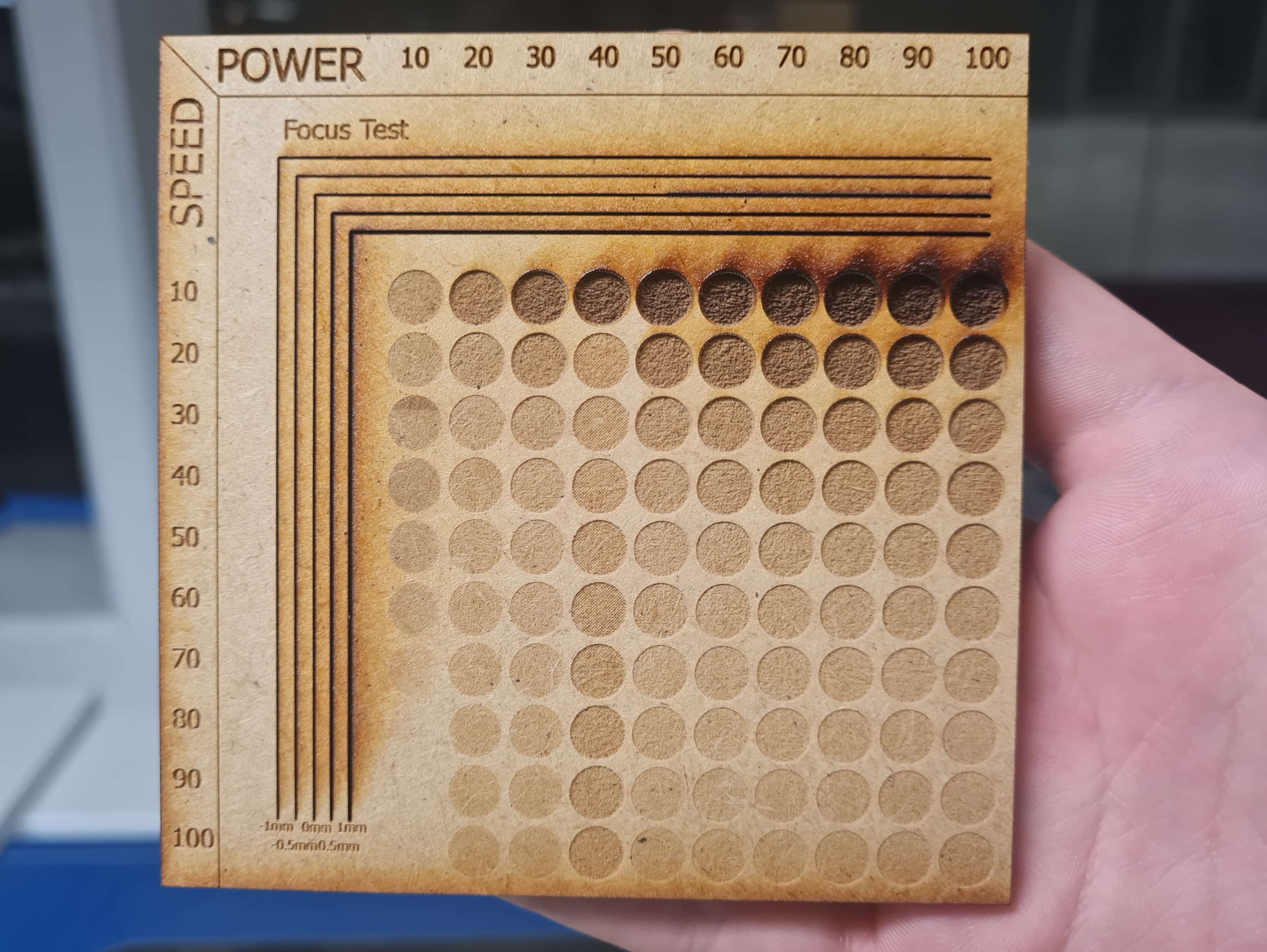
To test and optimize these parameters effectively, we've devised a simple yet robust experiment using Inventor Professional. This experiment aids in refining the interplay of power, speed, and rate to achieve desired outcomes efficiently.
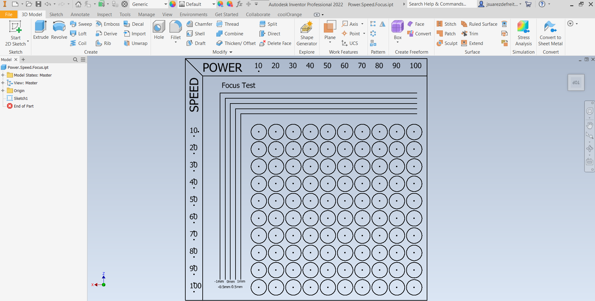
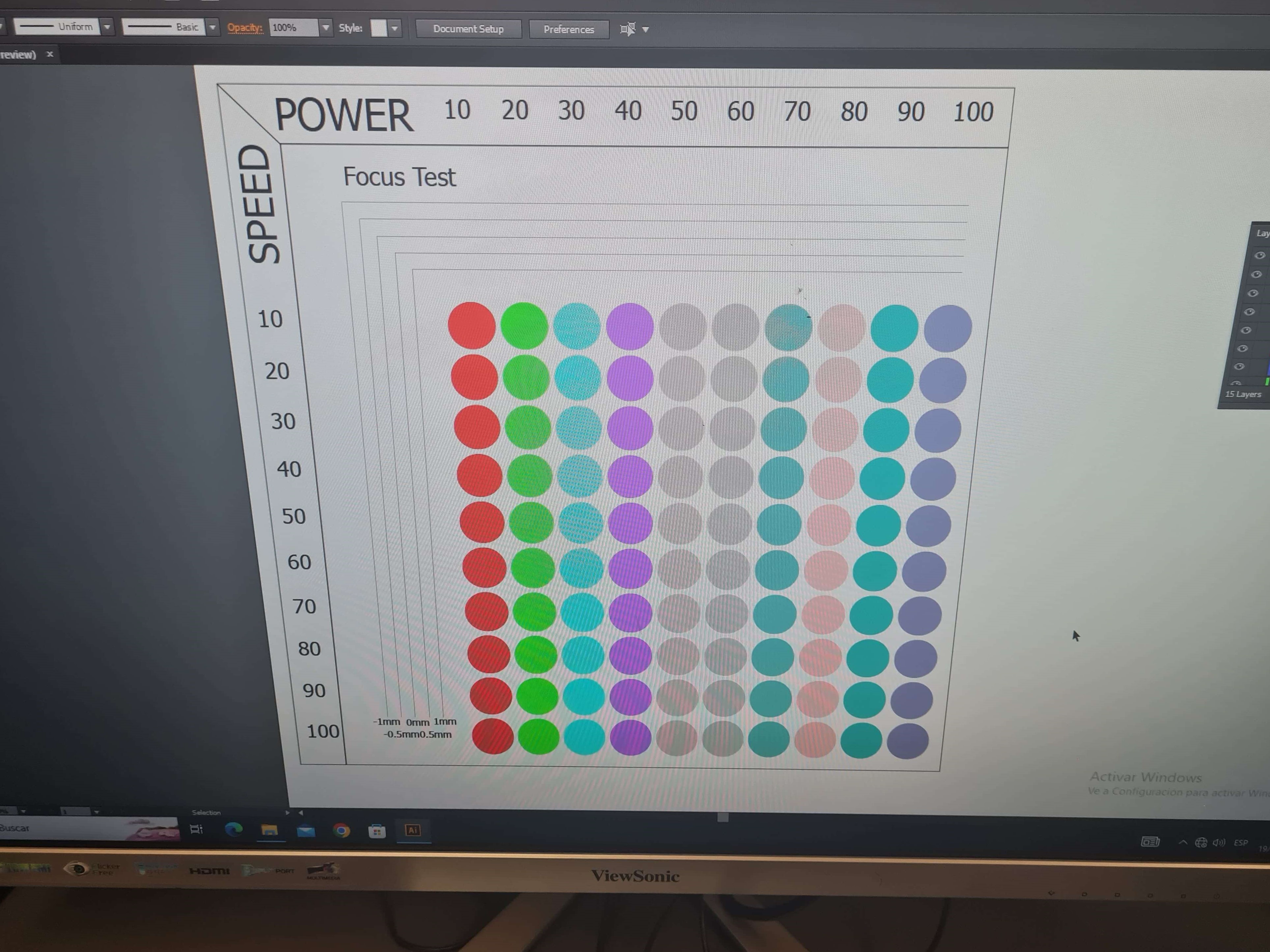
For this task, we utilized a function in the laser software called Color Mapping. This feature allows for the variation of cutting or engraving parameters by assigning different colors. Additionally, it provides a way to prioritize cutting in a specific order. This function proved to be immensely helpful. However, one limitation encountered was the maximum number of colors allowed for a job, which in this laser cutter's case, is 15. Consequently, I had to engrave in separate jobs. I opted to send the engraving by rows and adjust values for each of the 10 rows accordingly.
For the focus test, first, we set the correct height for the optimal focus. Then, for each pass, we vary the z-axis using the jog axis function. We run the test from -1mm to 1mm to examine how focus affects the quality and sharpness of the cut or engraving.
Kerf:
The kerf is the width of the line resulting from a laser cut. Adjusting this parameter is important to ensure that the cut pieces have the desired dimensions and to minimize wasted material. It should be taken into account when designing and cutting files and setting up the machine.
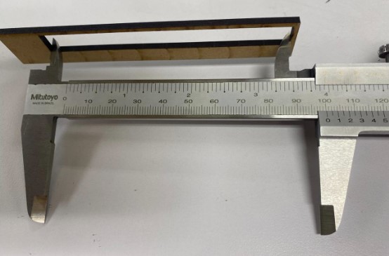
The first step was to cut ten pieces of equal size, in the image shown below each square measures 10mm per side.
Afterwards, we proceed to measure the distance between all the squares together with their initial measurement. We use a vernier with a precision of 0.05mm.
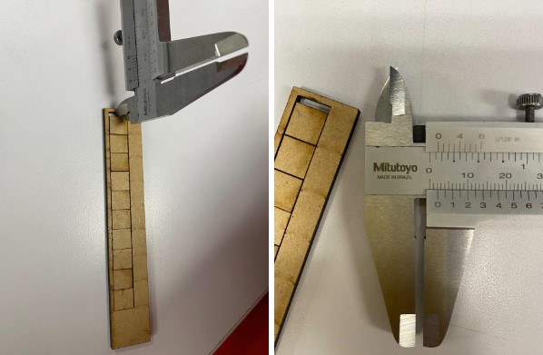
We also measured the total distance that the ten equal squares occupied.
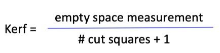
Finally, we apply the following formula to find the kerf, resulting in a kerf of 0.20 mm. This kerf was then used to edit the model in the software Fusion 360.
Designing for this machine:
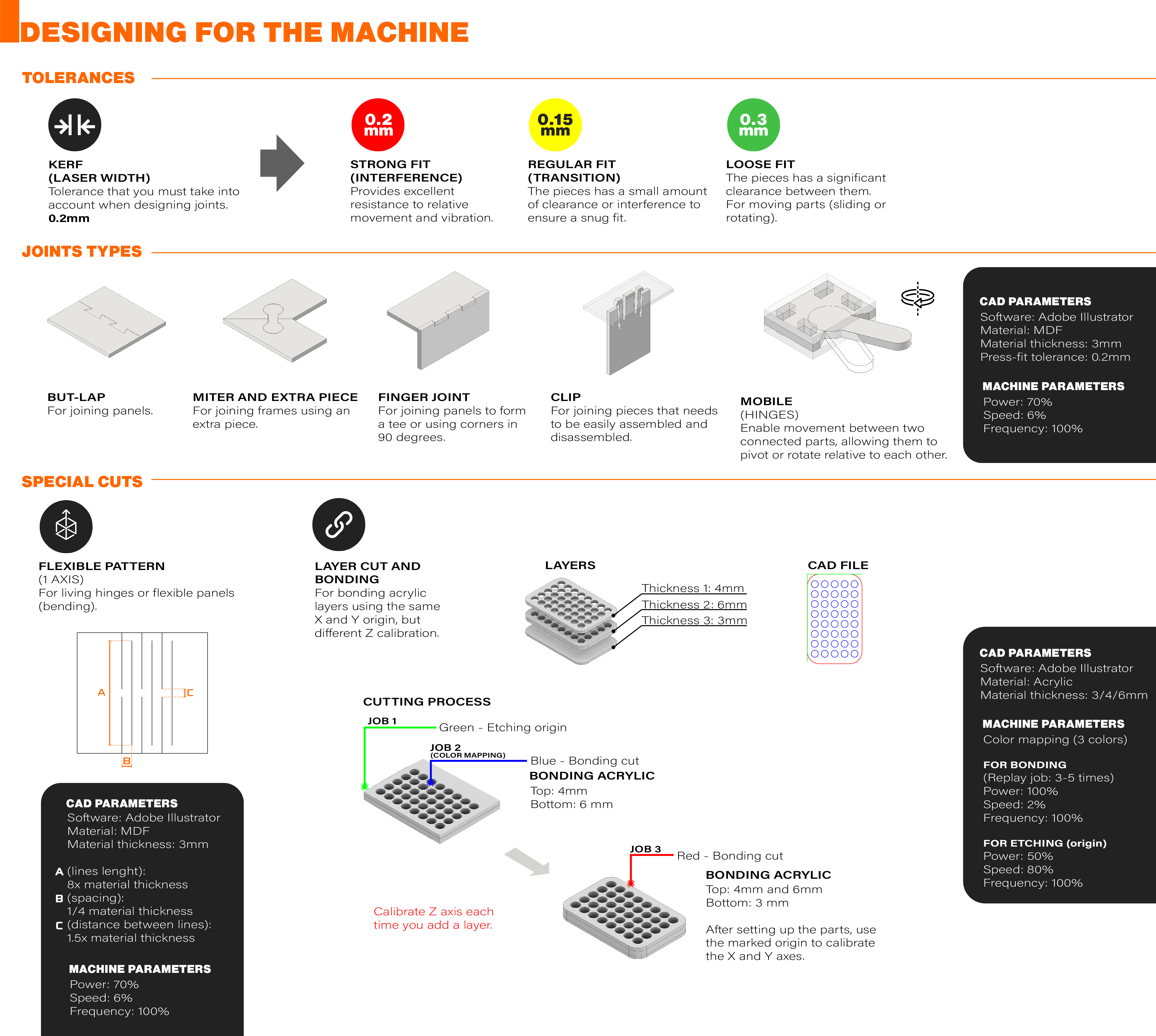
Joints clearances:
- Strong (interference) fit: The dimensions of mating parts are intentionally designed to be slightly larger and smaller than each other, respectively. Provides excellent resistance to relative movement and vibration.
- Regular (transition) fit: The dimensions of mating parts are designed to have a small amount of clearance or interference (kerf). This allows for easy assembly while providing some degree of interference to ensure a snug fit.
- Loose Fit: The dimensions of mating parts are intentionally designed to have significant clearance between them. This allows for easy assembly and disassembly without the need for force or precision fitting. Commonly used as sliding fits for shafts. Provides flexibility and tolerance for variations in dimensions while maintaining functionality and alignment.
Joints types:
- But-lap joint: Involves joining two materials end-to-end with partially overlapping. Increases bonding surface area and distributes stress. Suitable for applications where you need to join two boards.
- Finger joint: Known for its interlocking design resembling fingers. Provides excellent strength and resistance to pulling forces. Requires precise cutting and fitting, often used in woodworking.
- Miter joint and extra piece: Both materials are cut at an angle and joined together to form a corner using an extra piece. Offers a visually appealing corner joint.
- Clip joint: Used in applications where components need to be easily assembled and disassembled without the need for additional fasteners or tools. They provide a convenient and efficient way to join parts while allowing for quick and simple maintenance or replacement.
- Mobile joints: Enable movement between two connected parts, allowing them to pivot or rotate relative to each other (hinges).
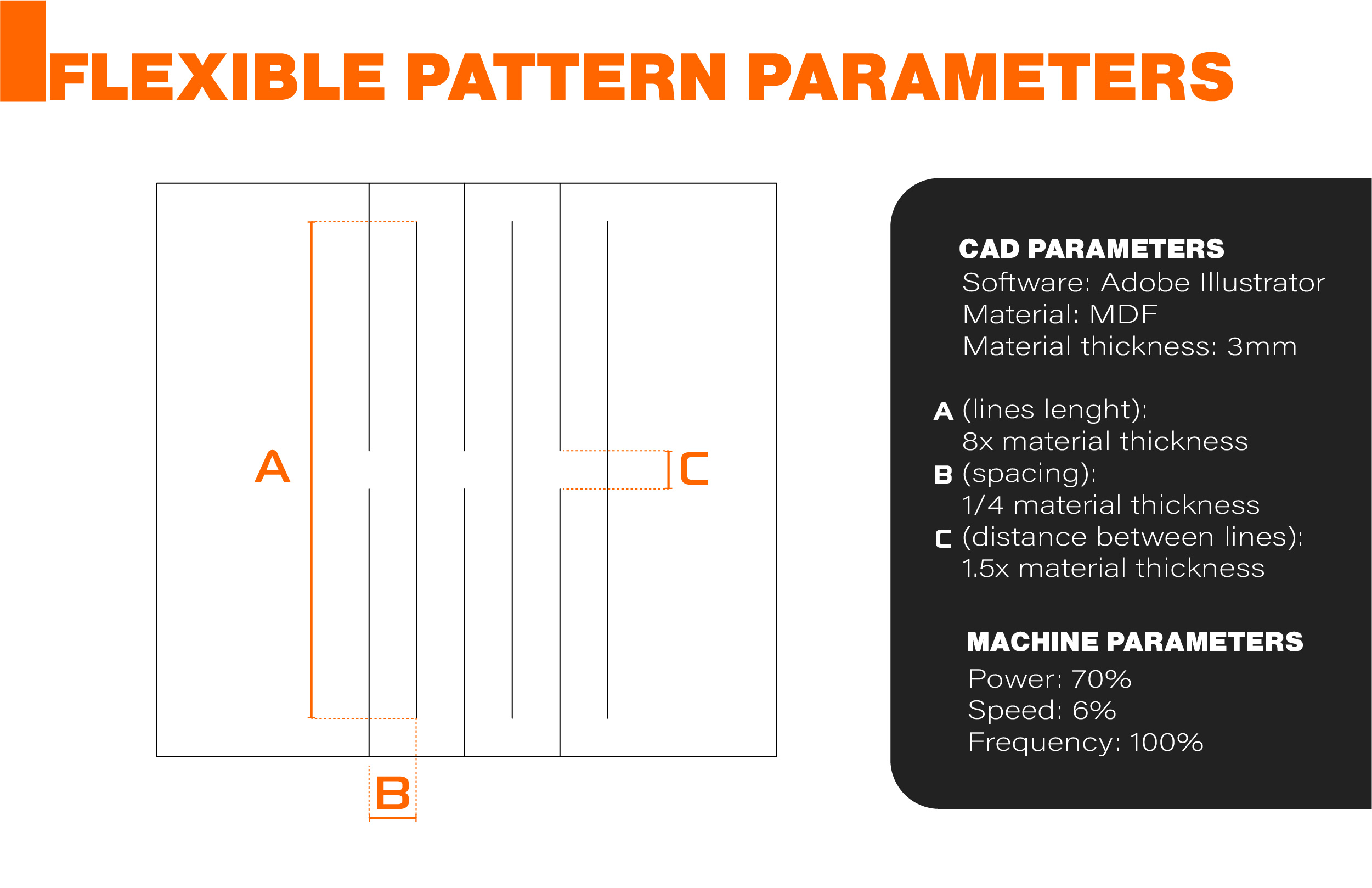
Special cuts:
1 (living hinges) and 2 axis (flexible boards).
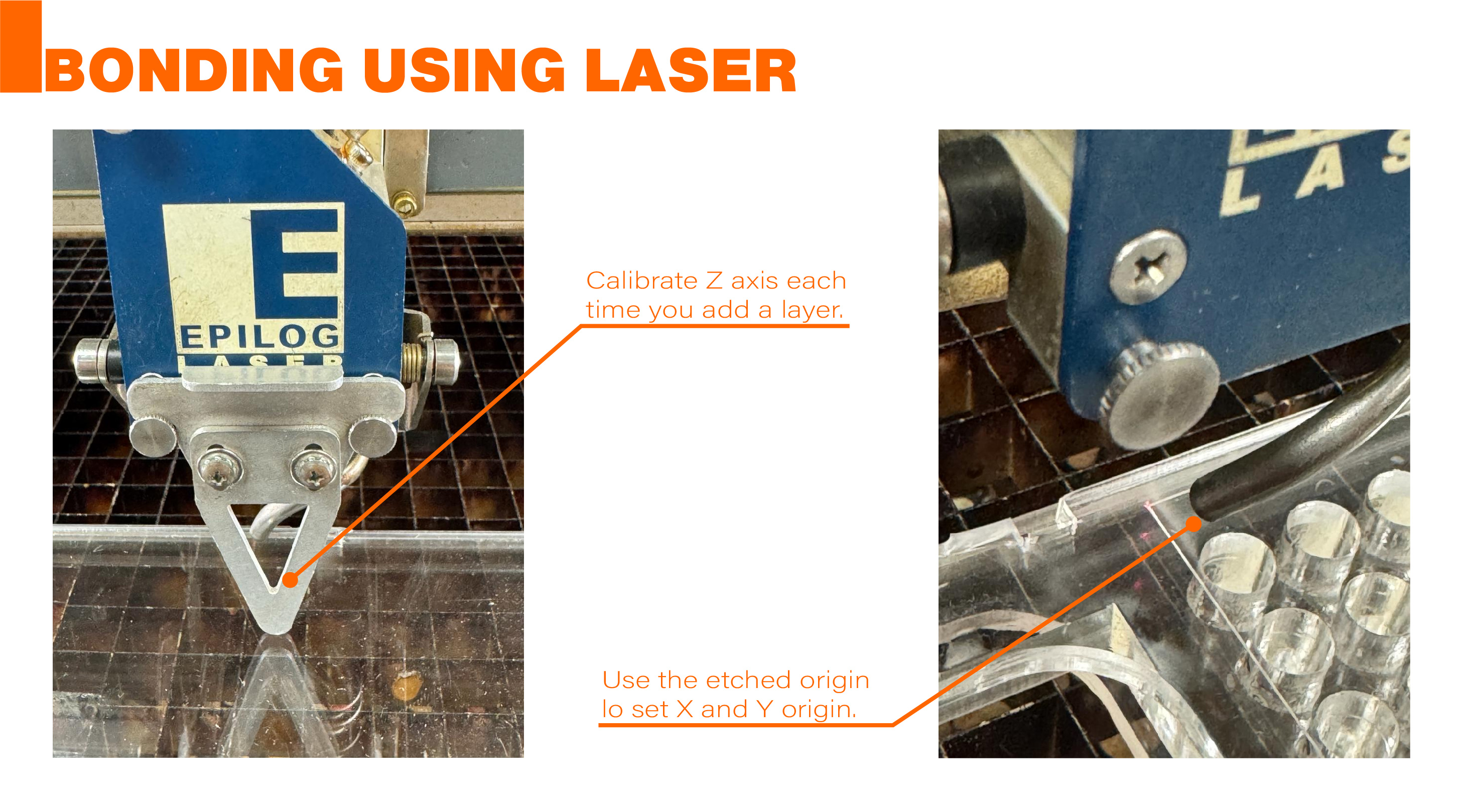
Layer cut and bonding:
For cutting and assembling various acrylic pieces across multiple layers.
Special cuts results: