

Week 14: Embedded Networking and Comunications
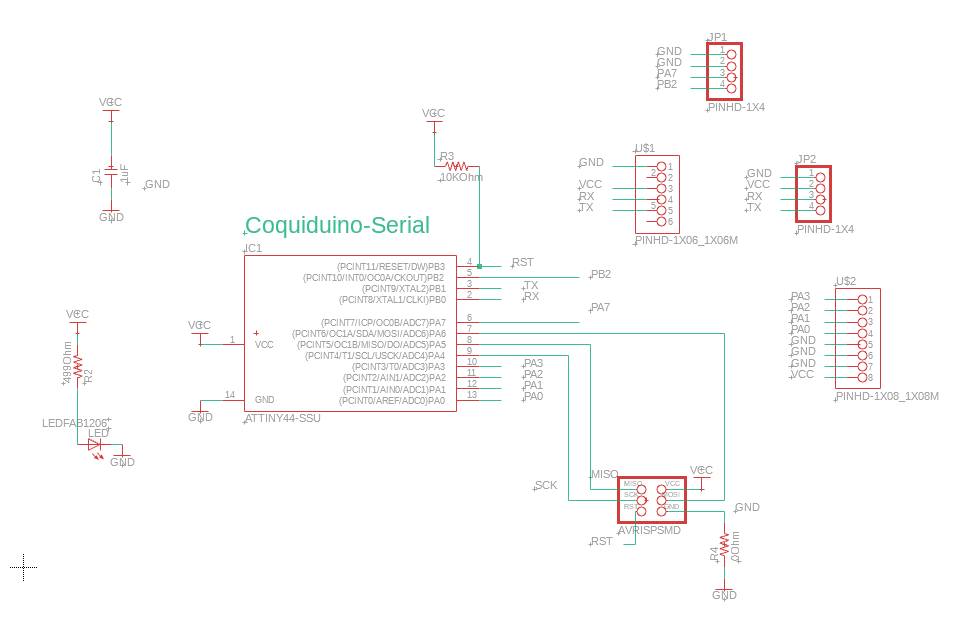
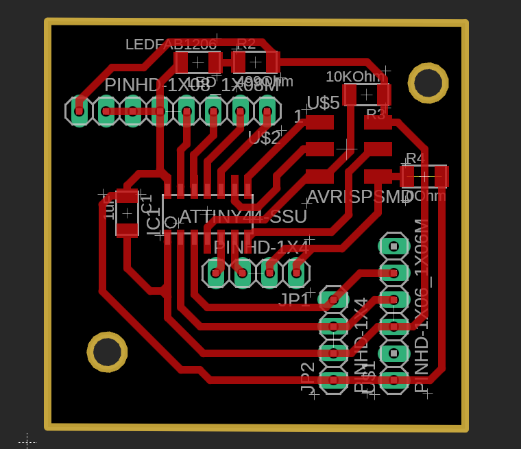
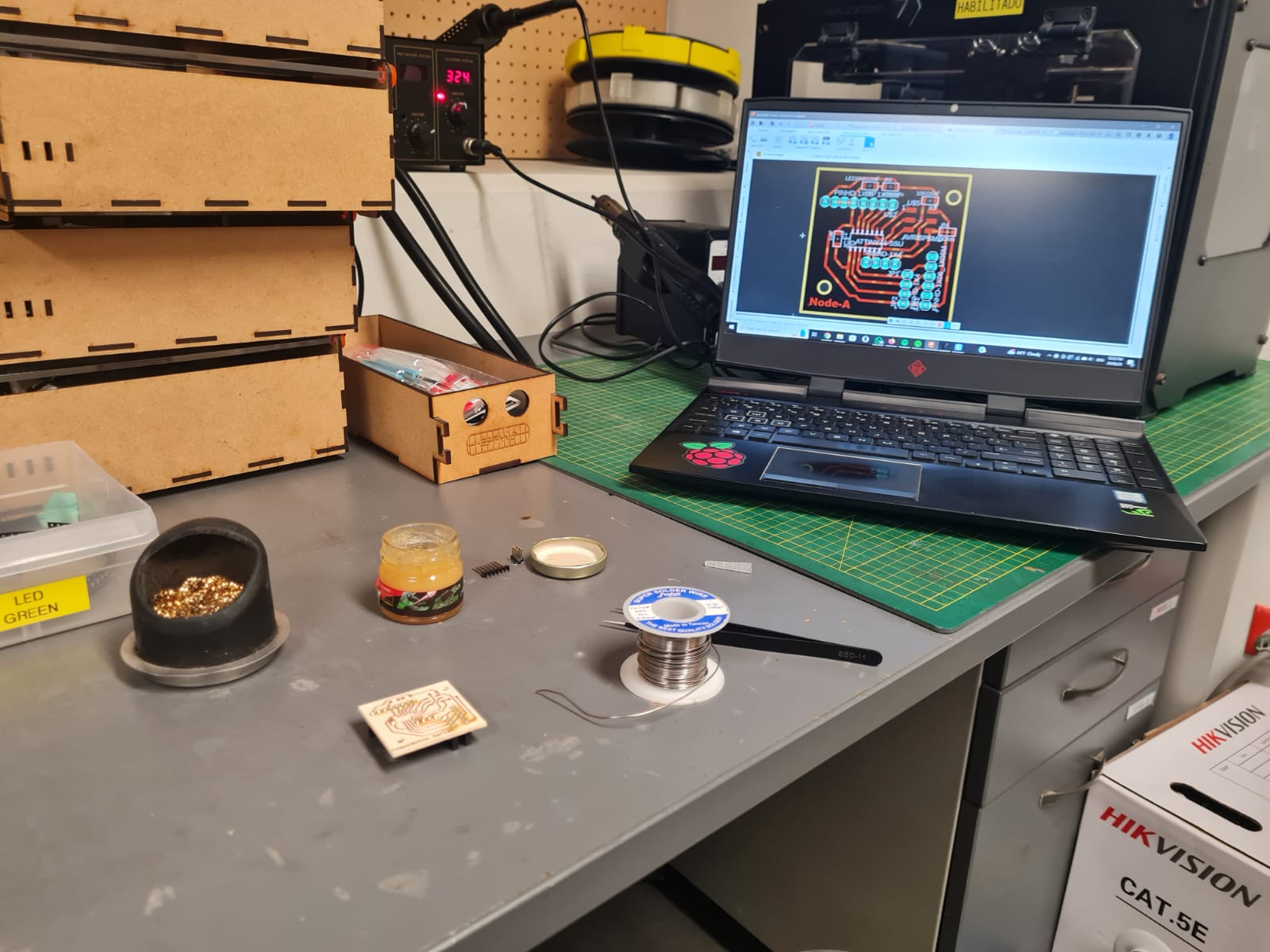
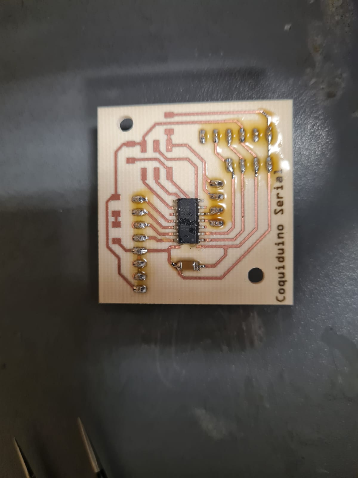
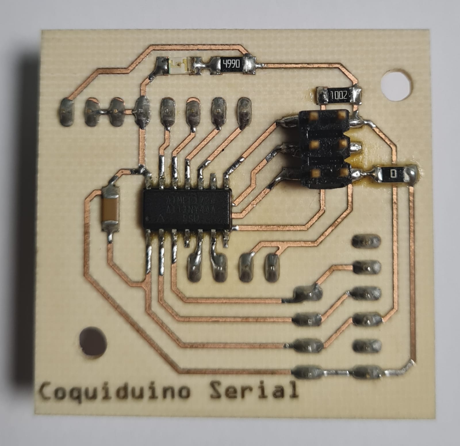
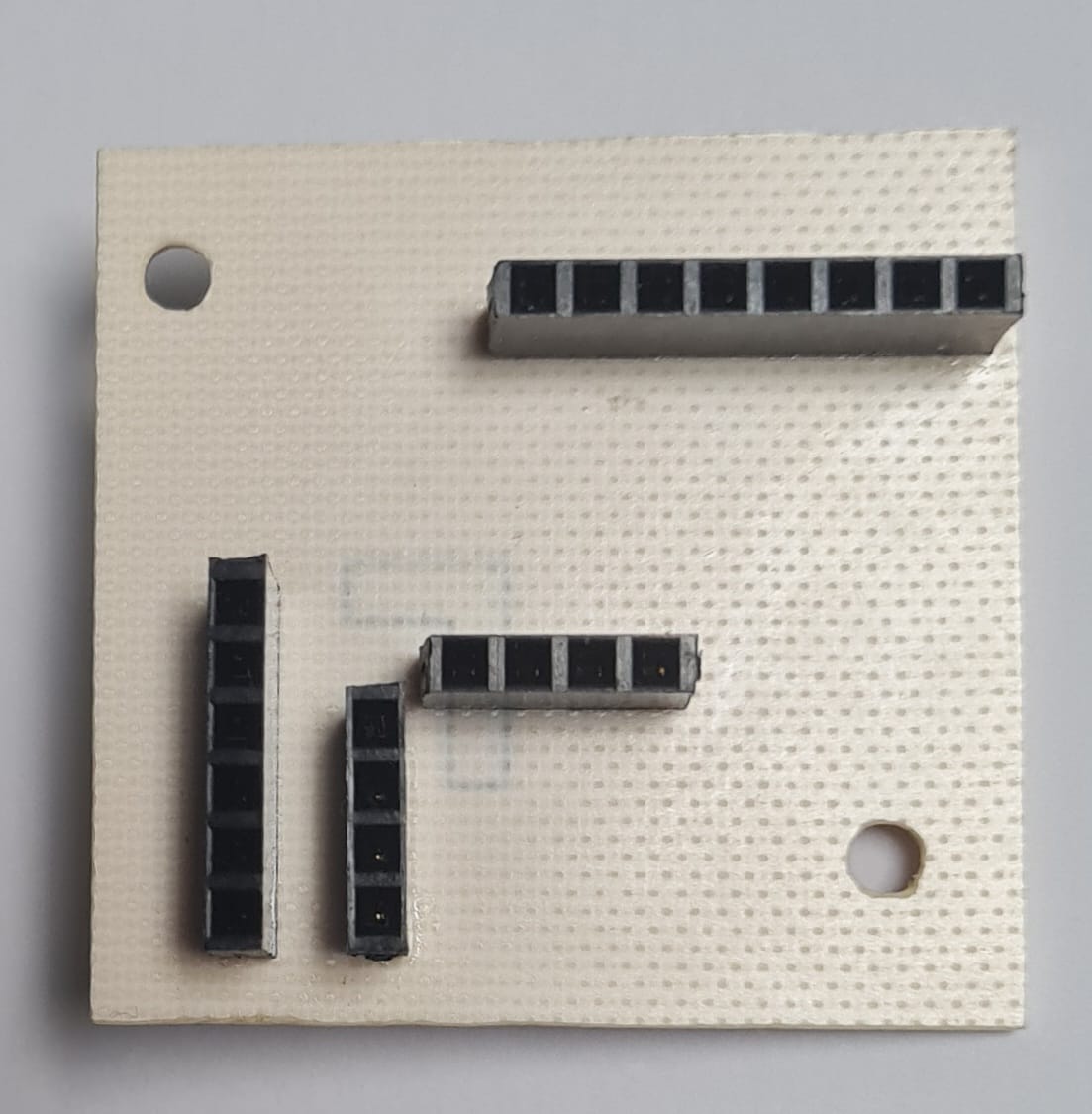
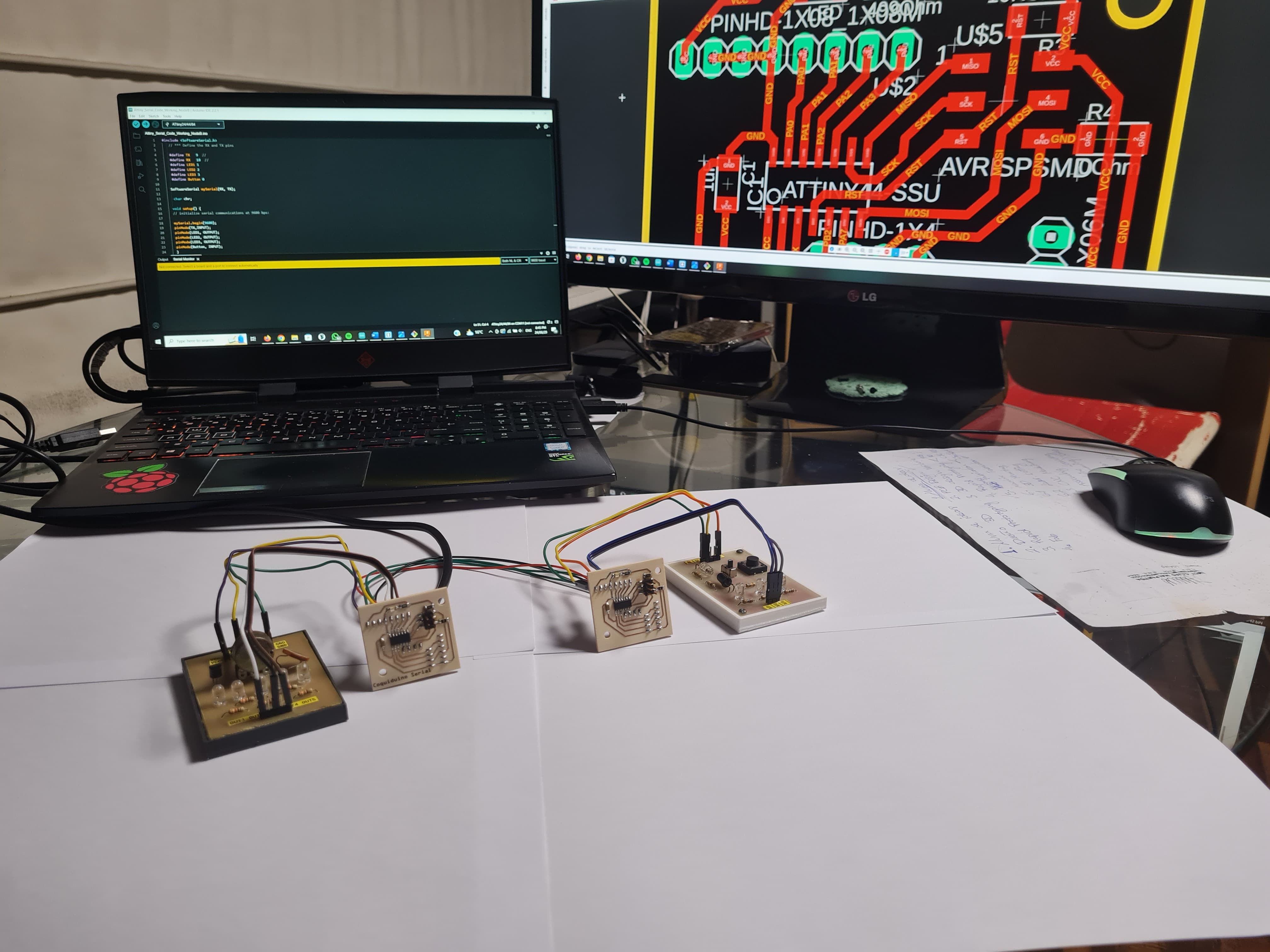
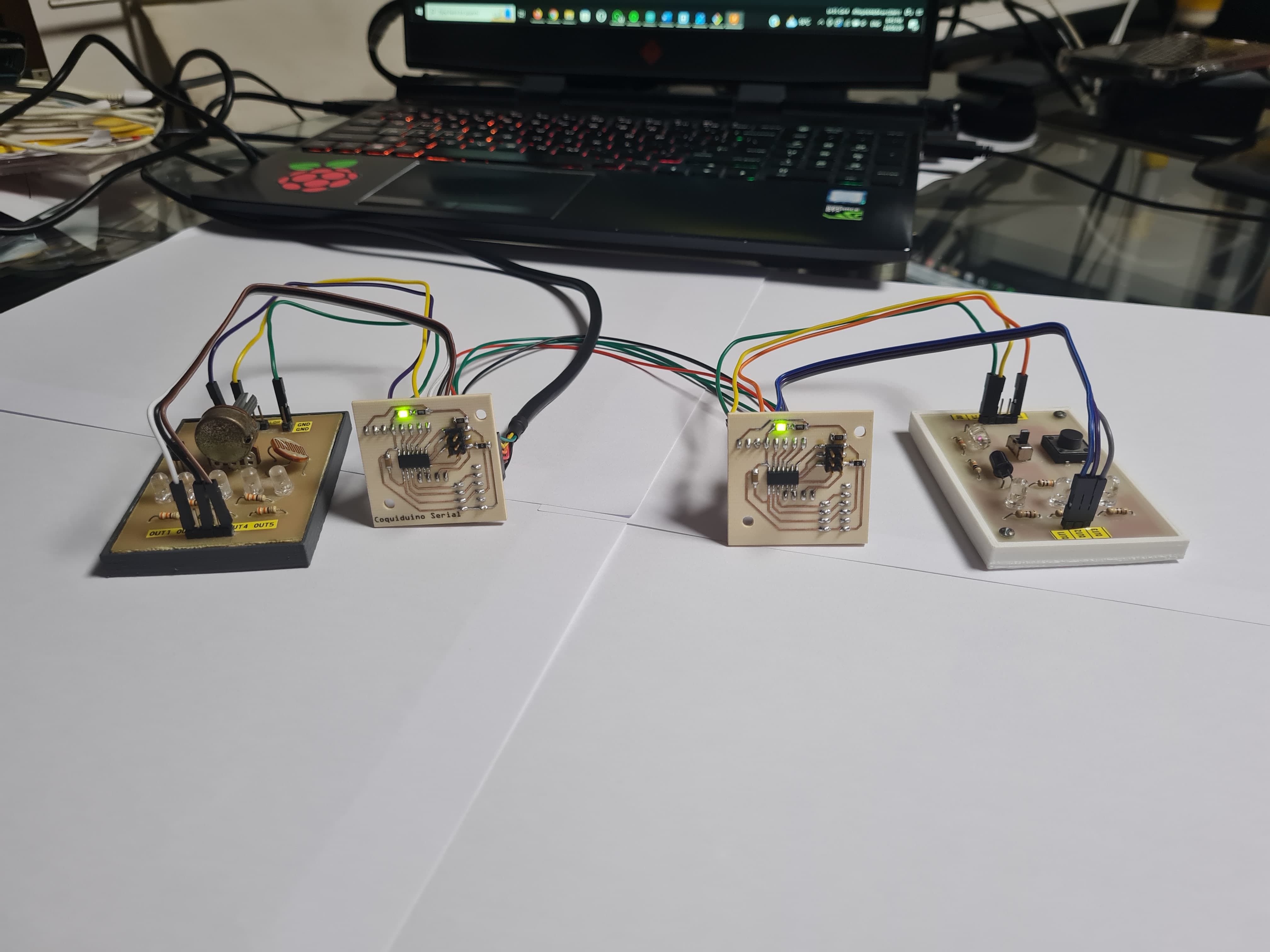
This week's assignment focuses on designing, building, and connecting wired nodes with network or bus addresses and a local interface. To achieve this, I designed the Coquiduino Serial Board, the setup features one TTL cable and two custom PCBs, each equipped with an ATtiny44 microcontroller operating as slaves in parallel. The project faced interference issues, necessitating a unique solution where the transmitter pin for each slave is set as an input by default and only set to output when returning confirmation of readings. This setup allows all slave boards to follow commands from the master computer using the Arduino IDE.

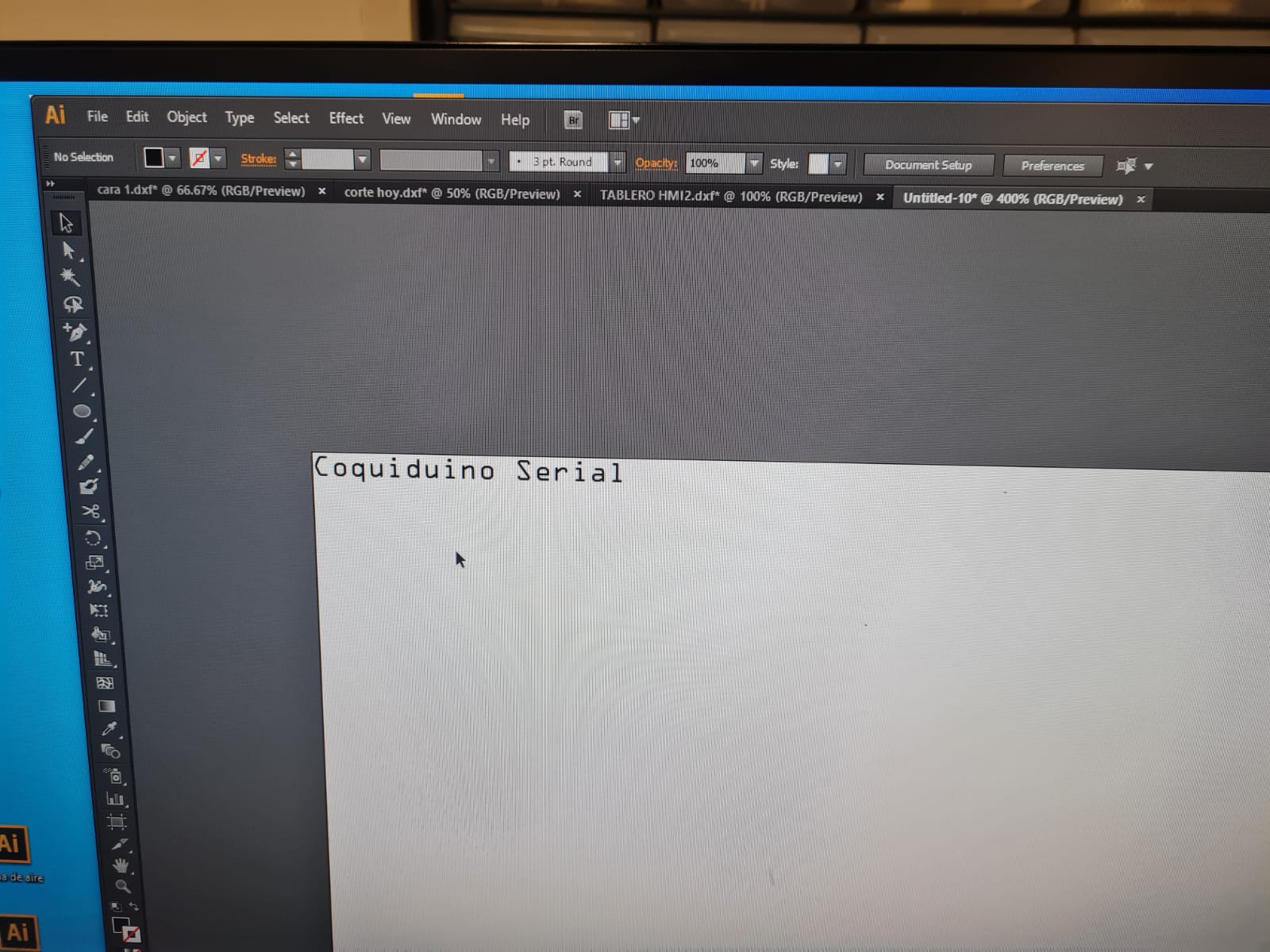
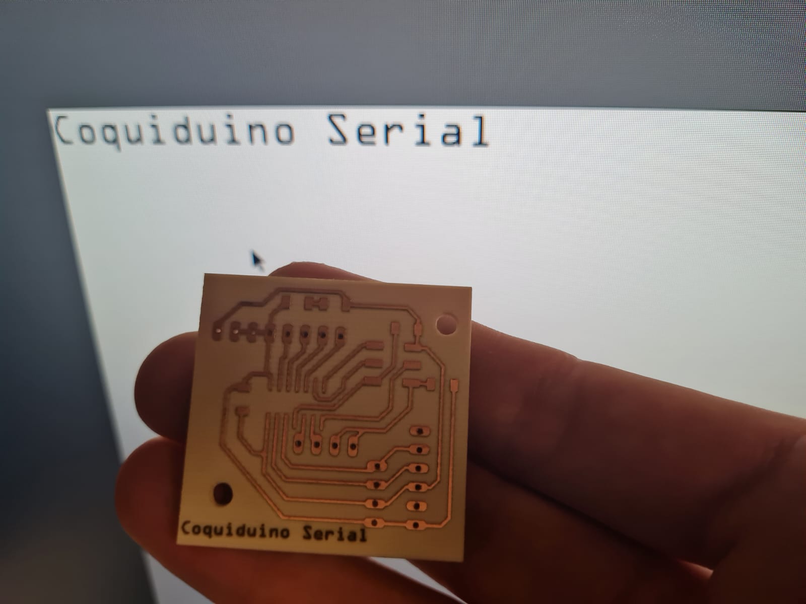
I was excited to try engraving the ceramic PCB with the CNC laser. The results were very good.
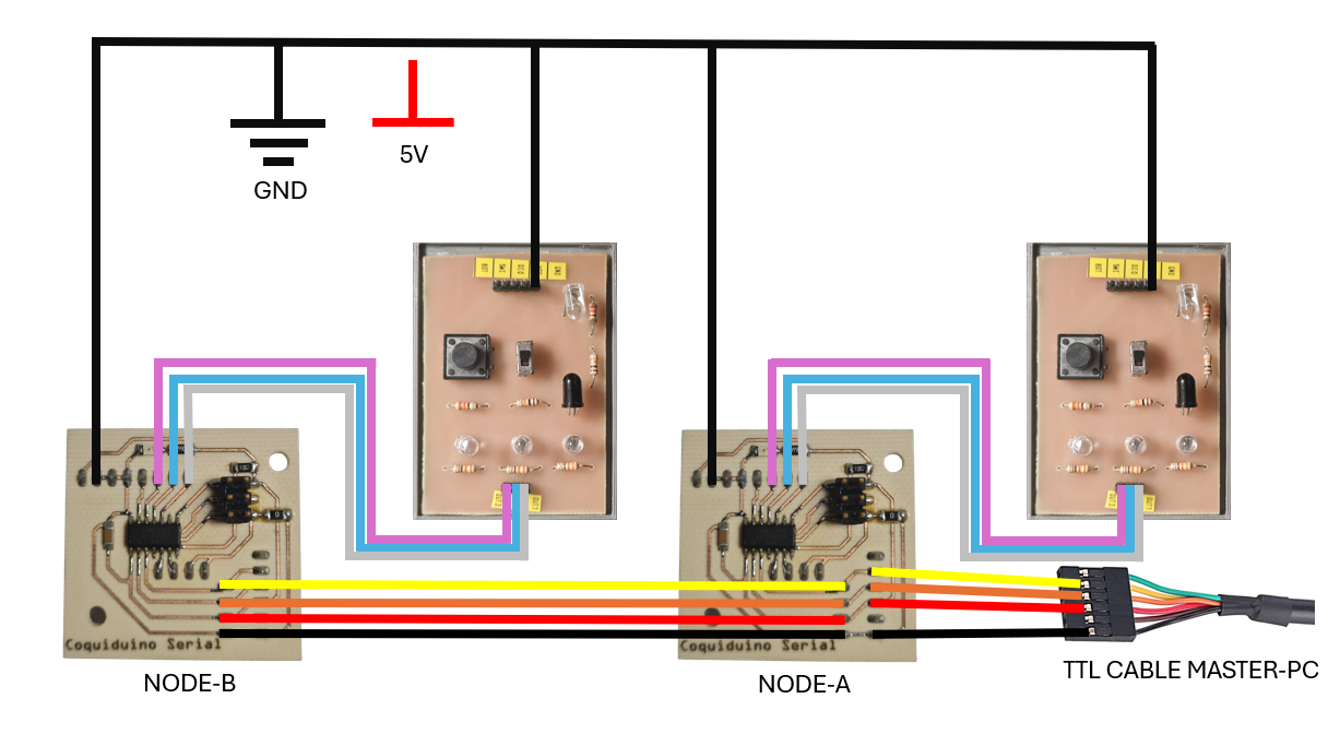
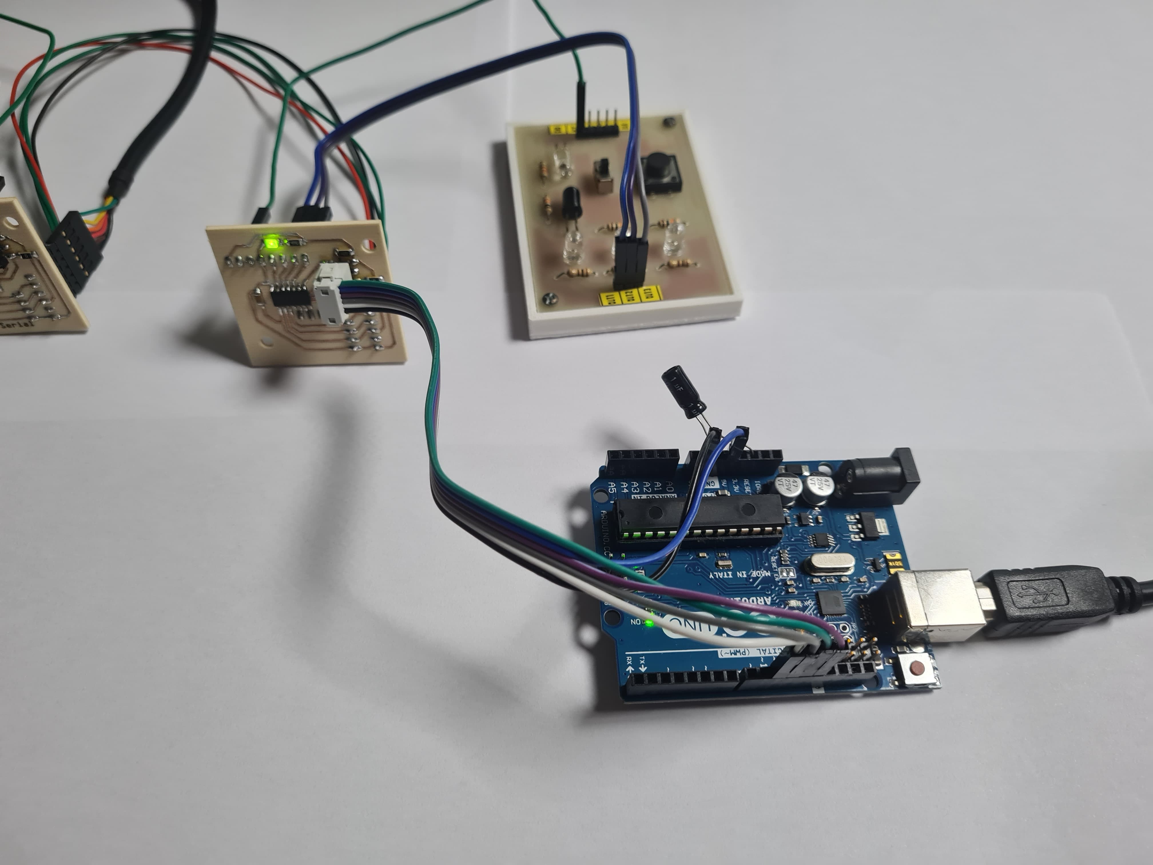
In this setup, we have two ATtiny44 microcontrollers acting as slave nodes. Each node performs specific actions based on commands received from the master PC via serial communication.
For the programming, I followed guidance from Samuel Zegarra's assignment. He managed to block the transmitter pin by setting it to input (tri-state) when not sending a command, ensuring that the RX pins of the slaves are always set to input and ready to receive data. The Tx pin is initially set as an input and only switched to output when data needs to be transmitted. After each transmission, the Tx pin is set back to input.
Node A controls three LEDs and a temperature sensor (LM35). When it receives the command 'a' from the master, it sequentially powers on the three LEDs. When it receives the command 'T', it reads the current temperature from the LM35 sensor and sends this reading back to the master.
We use the SoftwareSerial library to handle serial communication since the ATtiny44 has limited hardware serial support. In the setup() function, we initialize serial communication and set the LED pins as outputs. In the loop() function, we check if there is any data available from the serial input. If the command 'a' is received, the LEDs are powered on sequentially with a delay between each. If the command 'T' is received, the code reads the analog value from the temperature sensor (LM35), converts it to a temperature reading, and sends this value back to the master via serial communication.
    // Program Code: Attiny44_Serial_Node_A //

    // Written by: Jorge Suarez de Freitas + Samuel Zegarra//

    #include <SoftwareSerial.h>
   // *** Define the RX and TX pins

   // Define the RX and TX pins
    #define TX 9   // Transmit pin
    #define RX 10  // Receive pin

    // Define the LED pins
    #define LED1 1
    #define LED2 2
    #define LED3 3

    // Define the LM35 sensor pin
    #define LM35 0

    // Initialize SoftwareSerial with RX and TX pins
    SoftwareSerial mySerial(RX, TX);

    void setup() {
      // Initialize serial communications at 9600 bps
      mySerial.begin(9600);

      // Set initial pin modes
      pinMode(TX, INPUT); // Set TX as input to ensure it's tri-stated (high impedance)
      pinMode(LED1, OUTPUT);
      pinMode(LED2, OUTPUT);
      pinMode(LED3, OUTPUT);
      pinMode(LM35, INPUT);
    }

    void loop() {
      // Read a character from the serial port
      char chr = mySerial.read();

      // Check if the character is 'a'
      if (chr == 'a') {
        // Blink LEDs sequentially
        digitalWrite(LED1, HIGH);
        delay(500);
        digitalWrite(LED1, LOW);
        delay(500);
        digitalWrite(LED2, HIGH);
        delay(500);
        digitalWrite(LED2, LOW);
        delay(500);
        digitalWrite(LED3, HIGH);
        delay(500);
        digitalWrite(LED3, LOW);

        // Transmit the character back
        pinMode(TX, OUTPUT); // Set TX as output to transmit data
        mySerial.println(chr);
        delay(1000); // Ensure transmission is complete
        pinMode(TX, INPUT); // Set TX back to input (tri-state)
      }
      // Check if the character is 'T'
      else if (chr == 'T') {
        // Read and transmit temperature
        lm35();
      }
    }

    void lm35() {
      // Read temperature from LM35
      int tempReading = analogRead(LM35);
      float voltage = tempReading * (5.0 / 1023.0);  // Convert analog reading to voltage
      float temperature = voltage * 100;  // Convert voltage to temperature (10mV per degree Celsius)

      // Transmit the temperature reading
      pinMode(TX, OUTPUT); // Set TX as output to transmit data
      mySerial.print("Temperature: ");
      mySerial.print(temperature);
      mySerial.println(" C");
      delay(1000); // Ensure transmission is complete
      pinMode(TX, INPUT); // Set TX back to input (tri-state)
    }
Node B controls three LEDs and a button. When it receives the command 'b' from the master, it sequentially powers on the three LEDs. When it receives the command 'm', it reads the state of the button (pressed or not) and sends this state back to the master.
Similar to Node A, we use the SoftwareSerial library for serial communication. In the setup() function, we initialize serial communication, set the LED pins as outputs, and set the button pin as input. In the loop() function, we check for incoming data from the serial input. If the command 'b' is received, the LEDs are powered on sequentially with a delay between each. If the command 'm' is received, the code reads the state of the button and sends this state back to the master via serial communication.
    // Program Code: Attiny44_Serial_Node_B //

    // Written by: Jorge Suarez de Freitas + Samuel Zegarra//

    #include <SoftwareSerial.h>
   // *** Define the RX and TX pins
    #define TX 9   // Transmit pin
    #define RX 10  // Receive pin

    // Define the LED pins
    #define LED1 1
    #define LED2 2
    #define LED3 3

    // Define the Button pin
    #define Button 0

    // Initialize SoftwareSerial with RX and TX pins
    SoftwareSerial mySerial(RX, TX);

    void setup() {
      // Initialize serial communications at 9600 bps
      mySerial.begin(9600);

      // Set initial pin modes
      pinMode(TX, INPUT); // Set TX as input to ensure it's tri-stated (high impedance)
      pinMode(LED1, OUTPUT);
      pinMode(LED2, OUTPUT);
      pinMode(LED3, OUTPUT);
      pinMode(Button, INPUT);
    }

    void loop() {
      // Read a character from the serial port
      char chr = mySerial.read();

      // Check if the character is 'b'
      if (chr == 'b') {
        // Blink LEDs sequentially
        digitalWrite(LED1, HIGH);
        delay(500);
        digitalWrite(LED1, LOW);
        delay(500);
        digitalWrite(LED2, HIGH);
        delay(500);
        digitalWrite(LED2, LOW);
        delay(500);
        digitalWrite(LED3, HIGH);
        delay(500);
        digitalWrite(LED3, LOW);

        // Transmit the character back
        pinMode(TX, OUTPUT); // Set TX as output to transmit data
        mySerial.println(chr);
        delay(1000); // Ensure transmission is complete
        pinMode(TX, INPUT); // Set TX back to input (tri-state)
      }
      // Check if the character is 'm'
      else if (chr == 'm') {
        // Check the button state and transmit it
        button(chr);
      }
    }

    void button(char chr) {
      // Ensure the received character is 'm'
      if (chr == 'm') {
        // Read the button state
        int state = digitalRead(Button);

        // Transmit the button state
        pinMode(TX, OUTPUT); // Set TX as output to transmit data
        mySerial.print("Button State: ");
        mySerial.println(state);
        delay(1000); // Ensure transmission is complete
        pinMode(TX, INPUT); // Set TX back to input (tri-state)
      }
    }
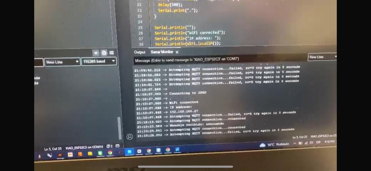
This week's assignment involved establishing communication between two Seeeduino Xiao ESP32 boards using Wi-Fi and the MQTT protocol to send messages.
To begin, our primary objective was to set up Wi-Fi communication between the two ESP32 boards and use the MQTT protocol to send and receive messages. For hardware, we used two Seeeduino Xiao ESP32C3 boards. In terms of software, we relied on the Arduino IDE, installing two libraries: WiFi.h for handling Wi-Fi connections and PubSubClient.h for managing MQTT communication.
For the MQTT broker, we used the server broker.hivemq.com and connected to a Mobile-Hotspot Wi-Fi network, using SSID and password to ensure a secure connection.
We successfully sent the word "avanzando" from one board to the other. One board acted as the publisher, sending the message to the MQTT topic, while the other board acted as the subscriber, receiving the message. This exercise helped us understand the flow of data in an MQTT system and the significance of topics in organizing message communication.
Successfully sending the message "avanzando" demonstrated our understanding of Wi-Fi and MQTT protocols, reinforcing the importance of reliable network connections and proper configuration in IoT projects. This assignment provided valuable experience for future wireless communication endeavors.