Week 14: Networking and Communication
Week 14: Networking and Communication
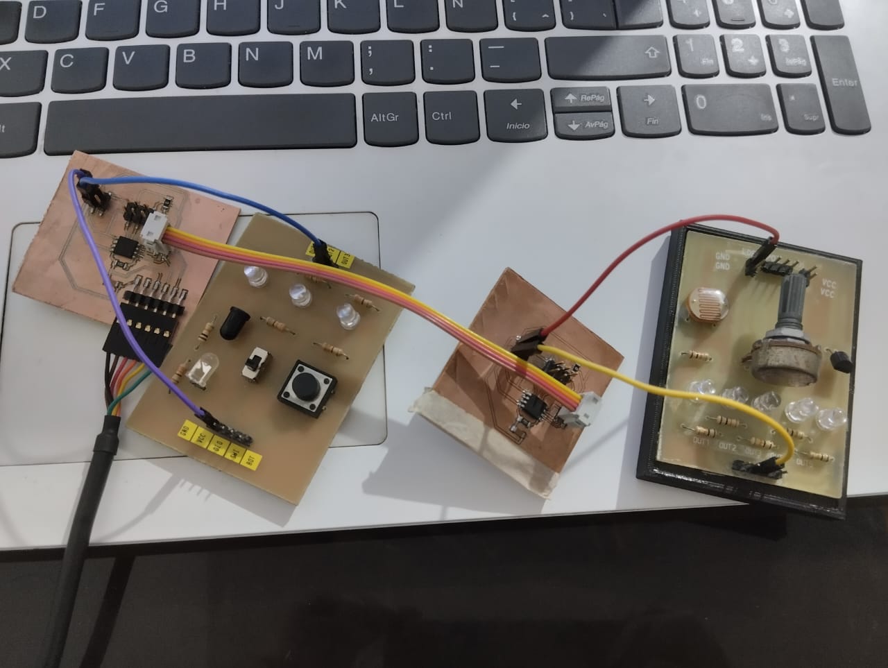
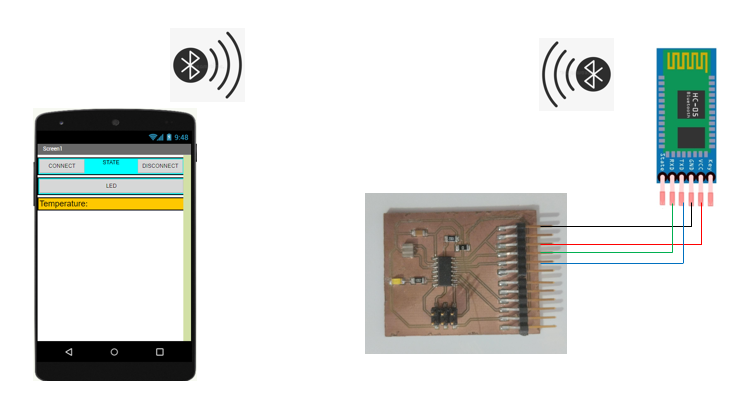
For the group project, I decided to perform wireless communication by connecting my cell phone with a board developed during the input devices week. For this, I required the use of an HC-05 module. The diagram of the connections is shown below.
Bluetooth communication is a wireless technology that allows devices to connect and exchange data over short distances. It uses radio waves to establish a low-power, secure communication link between two or more devices. Bluetooth is commonly used for connecting devices such as smartphones, headphones, speakers, smartwatches, and other peripherals. It operates in the 2.4 GHz frequency range and employs a technique called frequency hopping to reduce interference. Bluetooth supports various communication profiles that define specific use cases and functionalities, including hands-free, audio streaming, file transfer, and input device connections. Overall, Bluetooth communication provides a convenient and reliable method for wirelessly exchanging data between nearby devices, making it widely used in various applications and consumer electronics.
              #include <SoftwareSerial.h>

              SoftwareSerial monserial(1, 0); // rx and tx
              float tempC; // Variable to store the value obtained from the sensor (0 to 1023)
              int pinLM35 = 3;
              int led = A2;
              int msg;
              void setup() {
              // We configure the serial port to 9600 bps.
                  monserial.begin(9600);
                  pinMode(led,OUTPUT); }

              void loop() {
                  if (monserial.available()){
                    msg=monserial.read();
                    if(msg== 2){
                      analogWrite(led,1023);
                      delay(500);
                      msg=monserial.read();
                    }}
                else{
                  analogWrite(led,0);
                }
                  tempC = analogRead(pinLM35); // Read the signal from LM35 PIN
                  tempC = (5.0 * tempC * 100.0)/1024.0;  // Transform into Celcius
                   monserial.println(tempC);
                  delay(1000);}
Within this code, we are retrieving the temperature value from the LM35 sensor, converting it to Celsius, and transmitting it to the smartphone app. Make sure to set the rx and tx pins as follows: "SoftwareSerial monserial(1, 0)". Also we are receiving commands from the smartphone app to turn on a LED.
We use mit app inventor for the creation of the app called “temperature”. like this we are practicing for my final project.
We propose to create the design of the application, with the following visual:
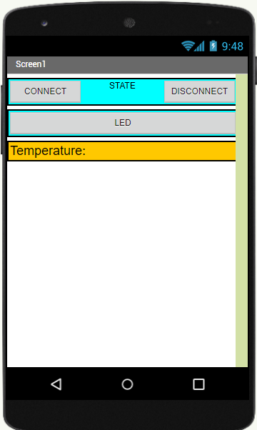
To develop the application, App Inventor provides the Blocks editor, which enables us to create a program using a block-based visual interface. It is user-friendly but requires some understanding of programming concepts.
Here is the program for the application developed using the Blocks editor in App Inventor:
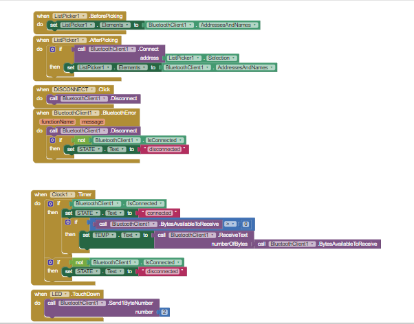
The first four blocks are used to establish a Bluetooth connection. The "clock1" block sets the refresh rate. You can make modifications to the app by downloading it from the download section.
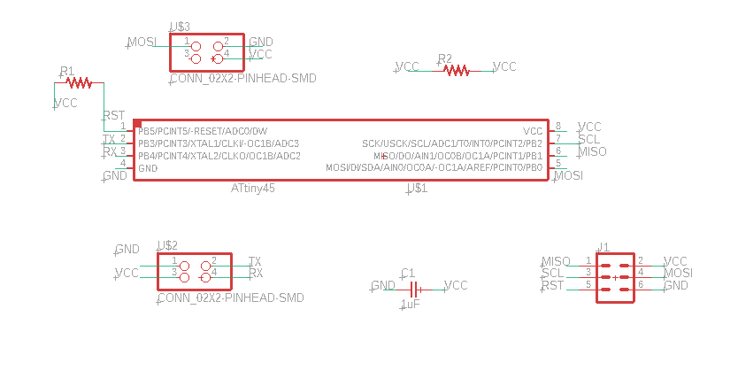
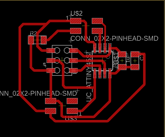
For this week, I decided to communicate with two microcontroller boards with Attiny45 using serial communication.The fundamental operation of this form of serial connection is to enable the devices to utilize the same Tx and Rx input for communication. Here is a simple diagram of the communication:
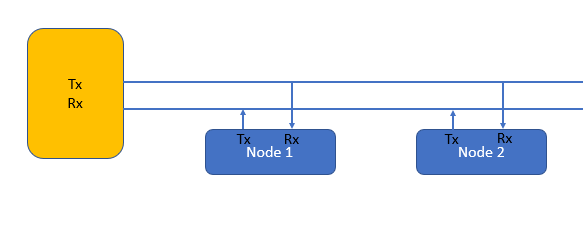
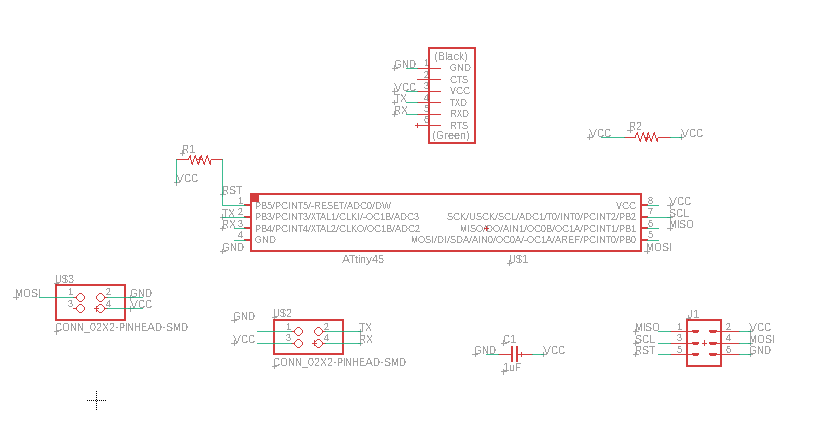
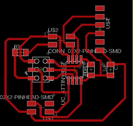
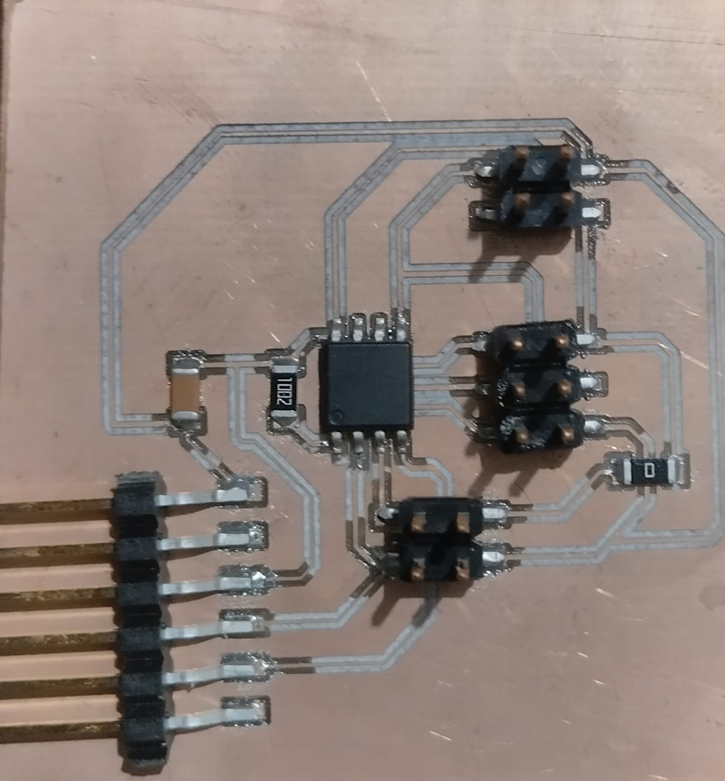
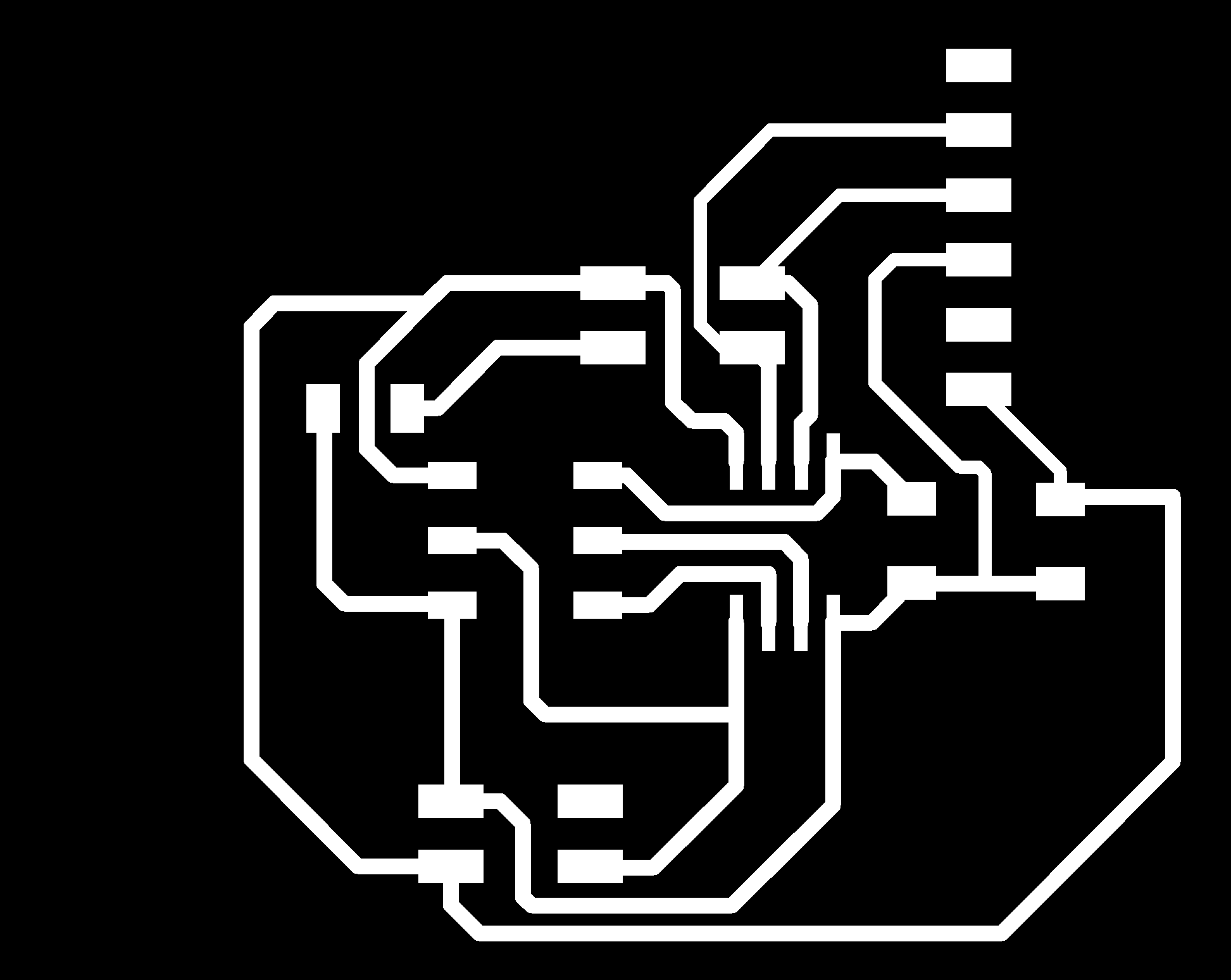
Based on the serial communication example provided by Neil, I designed 1 bridge and 1 node. Instead of using an LED, I decided to leave 3 pins open: Vcc, Gnd, and Signal, with the intention of being able to connect devices of different types.
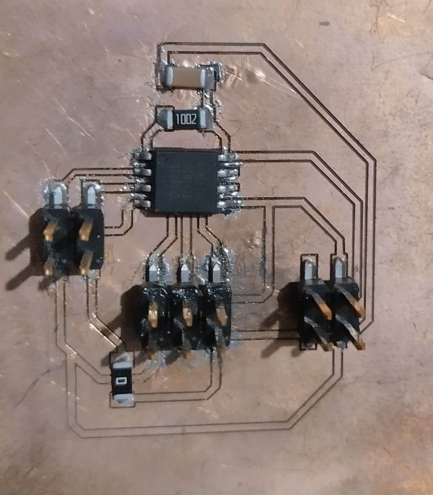
I tried to execute a code to establish serial communication between the 2 boards and the computer, but I failed. After several attempts, I decided to become familiar with serial communication using one board first and then connect the second one.
            #include <SoftwareSerial.h>

                // *** Define the RX and TX pins.a

                #define TX   4  // PB3, Pin 2 on attiny45 leg
                #define RX   3  // PB4, Pin 3 on attiny45 leg

                SoftwareSerial mySerial(RX, TX);

                char chr;

                void setup() {

                  // initialize serial communications at 9600 bps:

                  mySerial.begin(9600);

                  pinMode(0, OUTPUT);

                }

                void loop()

                {
                  char chr = mySerial.read();
                  mySerial.read();

                  if (chr == 'a') {
                    mySerial.print(chr);
                      digitalWrite(0, HIGH);
                      delay(500);
                      digitalWrite(0, LOW);
                      delay(500);
                  }

                  else if(chr == 'b')

                  {
                    mySerial.print(chr);
                      digitalWrite(0, HIGH);
                      delay(2000);
                      digitalWrite(0, LOW);
                      delay(2000);
                  }

                  else
                  {

                  }

                }
The code consists of reading the data entered through the serial monitor and turning on for 500 milliseconds if the data is "a", and turning on the LED for 1000 milliseconds if the data is "b". With this, I was able to verify that the bridge communicates properly with the computer.
It seems to work, now I will try adding one more board, the only difference being that each board will have an identification of "a" for the bridge and "b" for the node.
node code:
                #include <SoftwareSerial.h>

                    // *** Define the RX and TX pins.a

                    #define TX   4  // PB3, Pin 2 on attiny45 leg
                    #define RX   3  // PB4, Pin 3 on attiny45 leg

                    SoftwareSerial mySerial(RX, TX);

                    char chr;

                    void setup() {

                      // initialize serial communications at 9600 bps:

                      mySerial.begin(9600);

                      pinMode(0, OUTPUT);

                    }

                    void loop()

                    {
                      char chr = mySerial.read();
                      mySerial.read();

                      if (chr == 'b') {

                          mySerial.println(chr);
                          digitalWrite(0, HIGH);
                          delay(500);
                          digitalWrite(0, LOW);
                          delay(500);
                      }


                      else
                      {
                          digitalWrite(0, LOW);
                      }

                    }
The code reads the data entered through the serial monitor, "a" or "b", and based on that, verifies if the data matches its identifier. If so, it executes the condition where the LED is turned on.
As Niel explained, the nodes receive data quite easily, but there is something missing in the code for them to be able to send data back. This issue is resolved in Niel's example code, but it is written in C. If I can understand the logic, I hope to be able to receive data from the nodes. Additionally, in the video, it is shown that sometimes the LEDs do not react to the sent command.
Thanks to my global instructor i manage to figure out how to make the nodes send data back.
The Tx pin is initially set as an input (tri-state) and only switched to output when data needs to be transmitted. After each transmission, the Tx pin is set back to input.
                #include <SoftwareSerial.h>
                  // *** Define the RX and TX pins.a

                  #define TX   4  // PB3, Pin 2 on attiny45 leg
                  #define RX   3  // PB4, Pin 3 on attiny45 leg

                  SoftwareSerial mySerial(RX, TX);

                  char chr;

                  void setup() {
                    // initialize serial communications at 9600 bps:

                    mySerial.begin(9600);
                    pinMode(TX,INPUT);
                    pinMode(0, OUTPUT);
                  }

                  void loop()

                  {
                    char chr = mySerial.read();
                    mySerial.read();

                    if (chr == 'a') {
                       digitalWrite(0, HIGH);
                        pinMode(TX,OUTPUT);
                        mySerial.print(chr);
                        delay(1000);
                        pinMode(TX,INPUT);
                        digitalWrite(0, LOW);
                    }

                    else
                    {
                       digitalWrite(0, LOW);
                    }

                  }
TThis code is for the bridge, and for the node, just change the "a" to "b". When we send "a" through the serial, the bridge sends the letter back, and the LED turns ON. The same applies to the node with "b".