Final project
Final project
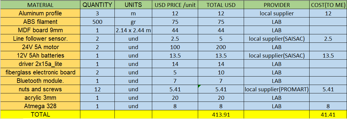
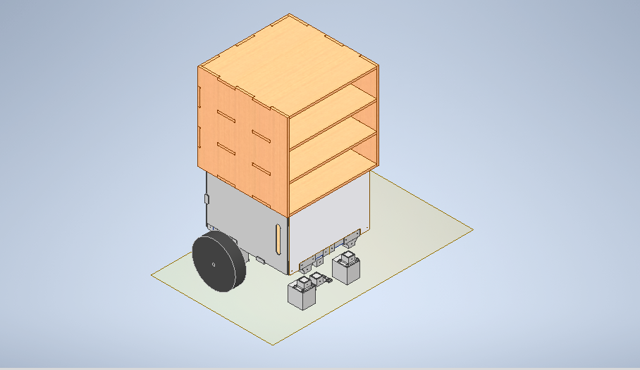
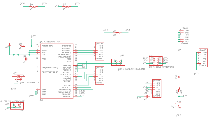
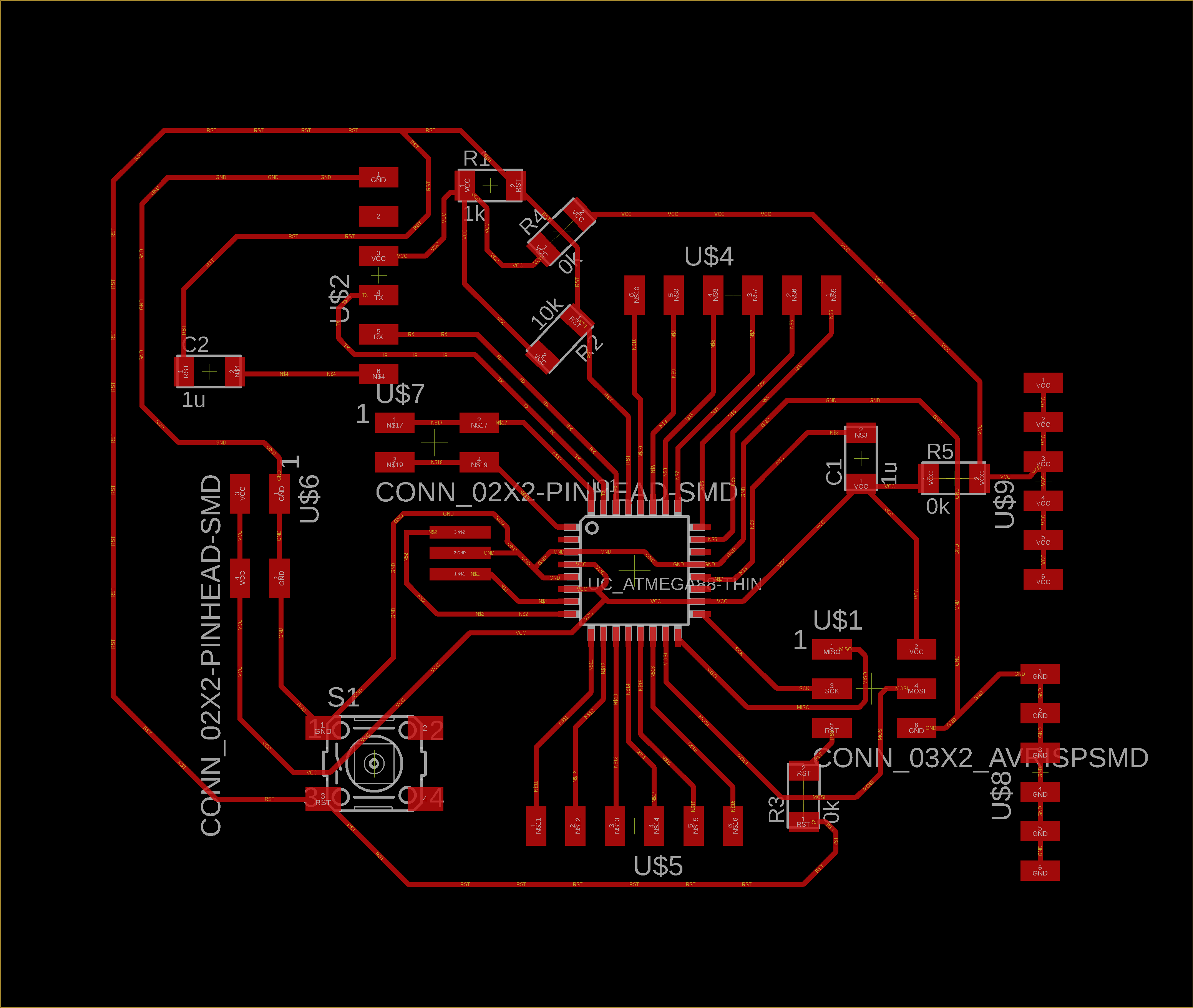
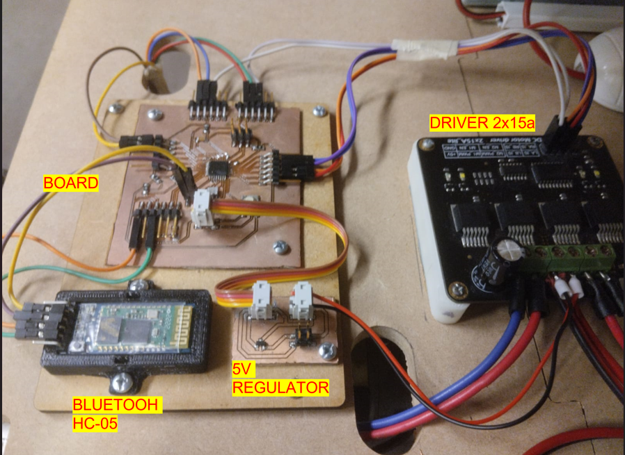
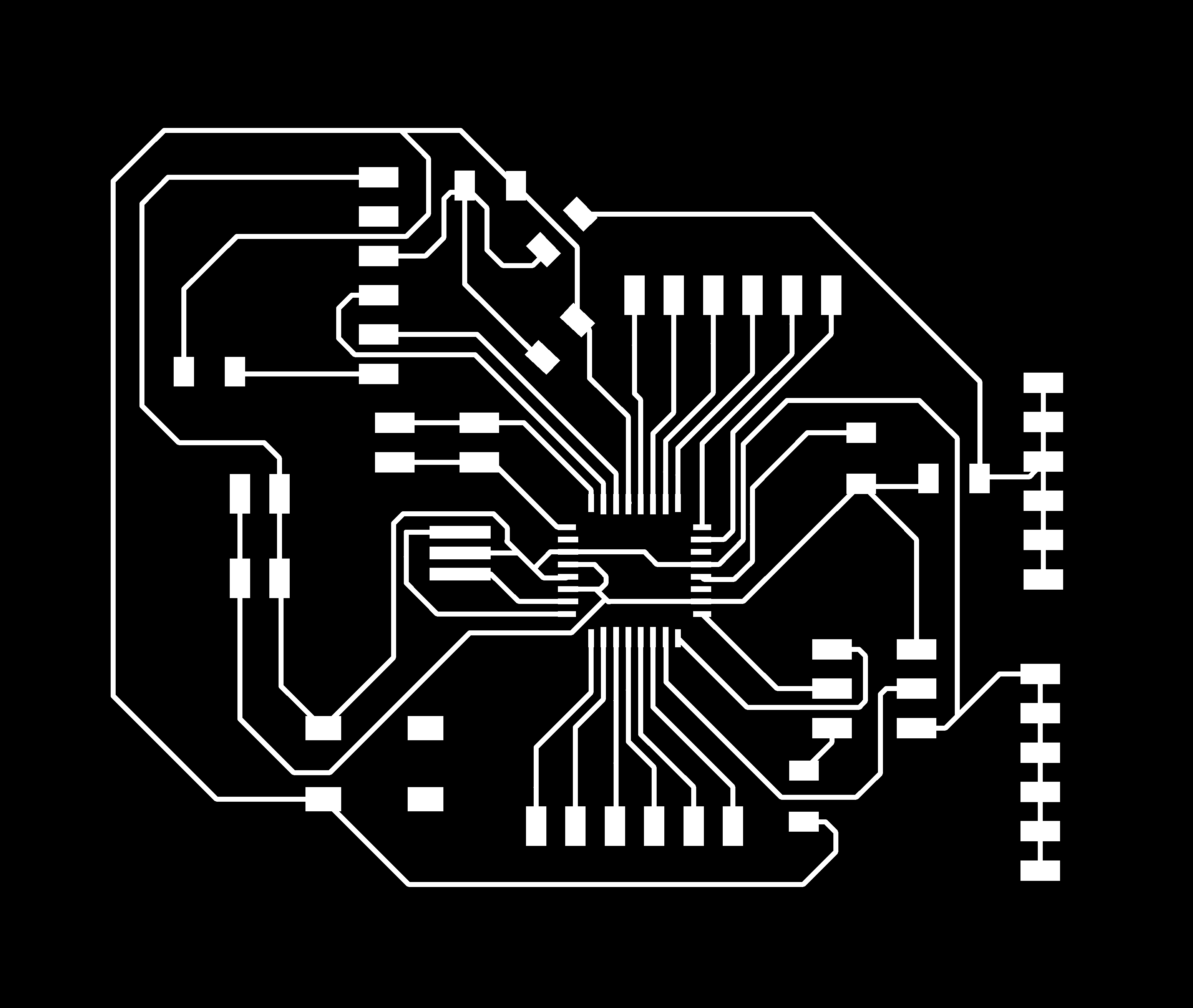
The robot will have the task of autonomously transporting the components and tools required for classes from the laboratory to the classroom. It will be equipped with line follower sensors for navigation, 12 - 24 V and 5A motors for movement, a 12V battery for power, a self-designed and SMD-soldered electronic board, and a Bluetooth module for communication.
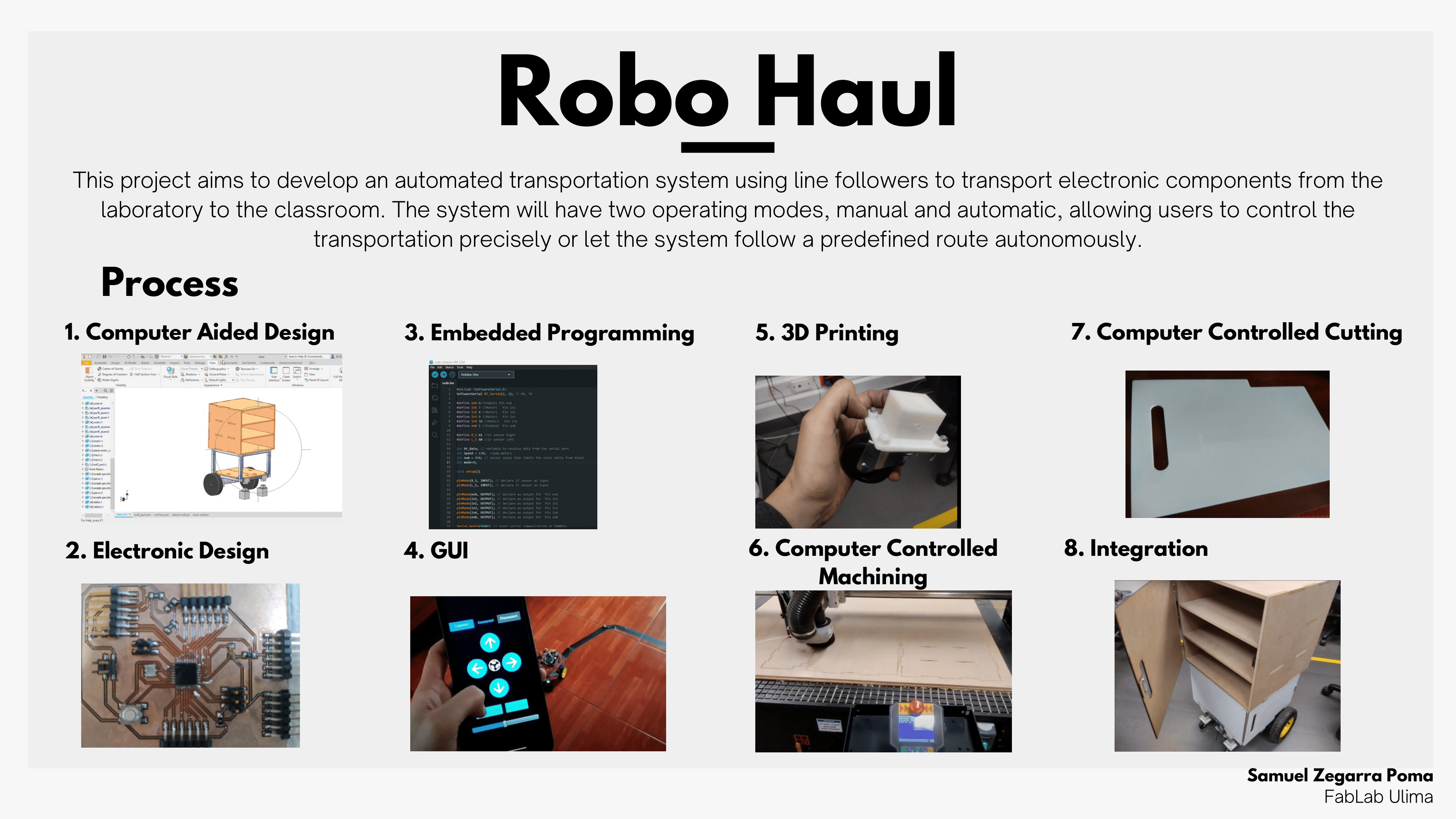
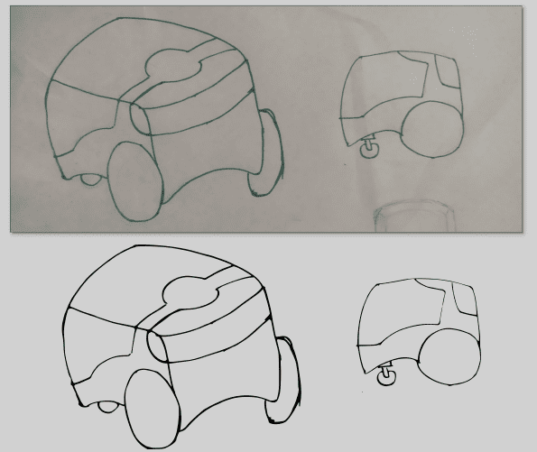

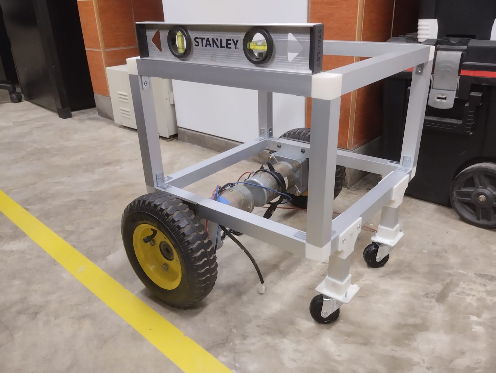
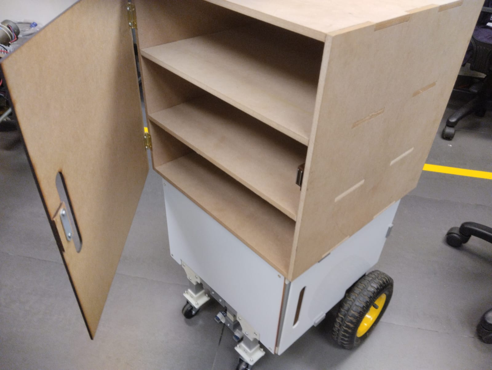
Presented here is the final design of my project, consisting of an aluminum profile chassis where the electronics, batteries, and attached motors will be housed. On top, there are MDF drawers where the components to be transported will be placed.
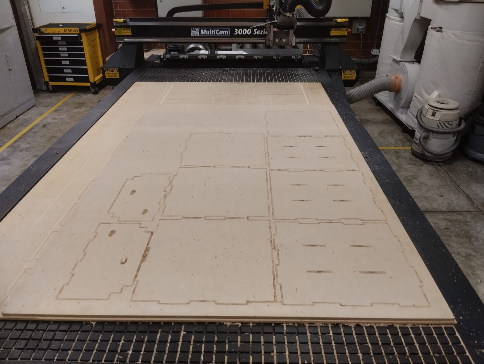
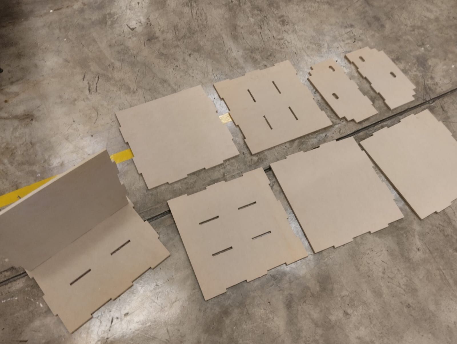
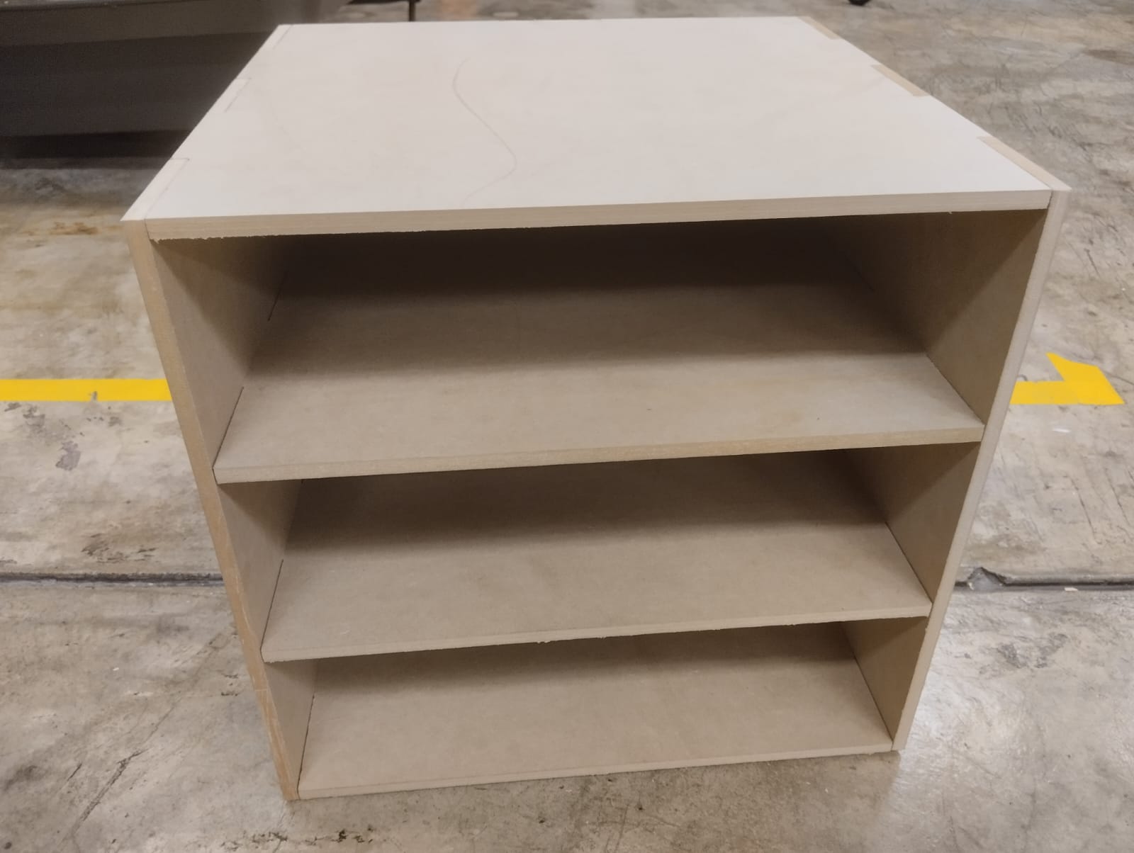
For the drawers i decided to use 9mm MDF. Based on the completed design, the parts were exported to proceed with the cutting process. The steps outlined in Week 6: Computer Controlled Machining were followed accordingly.
The chosen material for laser cutting was 3mm acrylic as a coating for the aluminum. The process we learned in Week 5: Controlled Cutting was followed accordingly.

The FDM printers were used to print the following ABS parts:
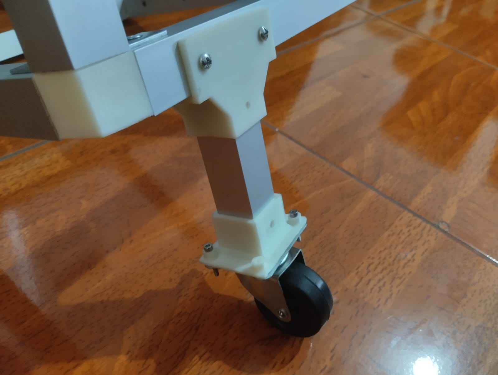
swivel caster wheel support:
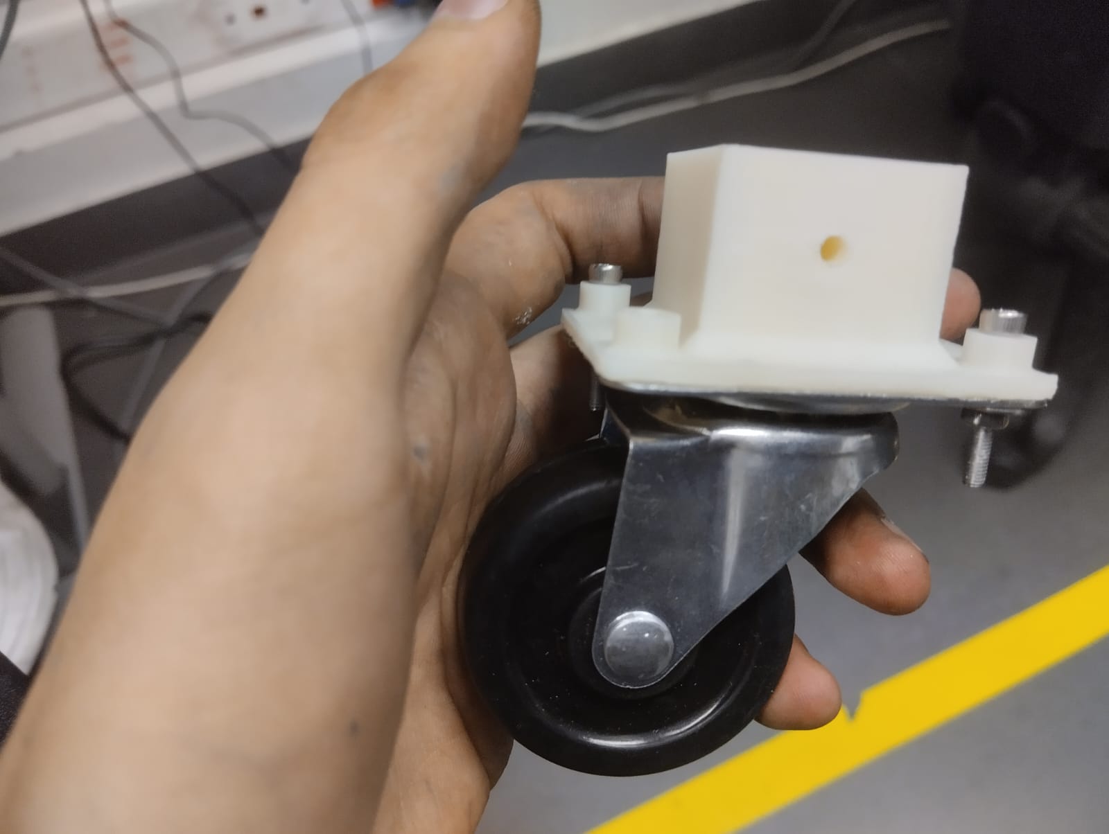
swivel caster wheel support 2:
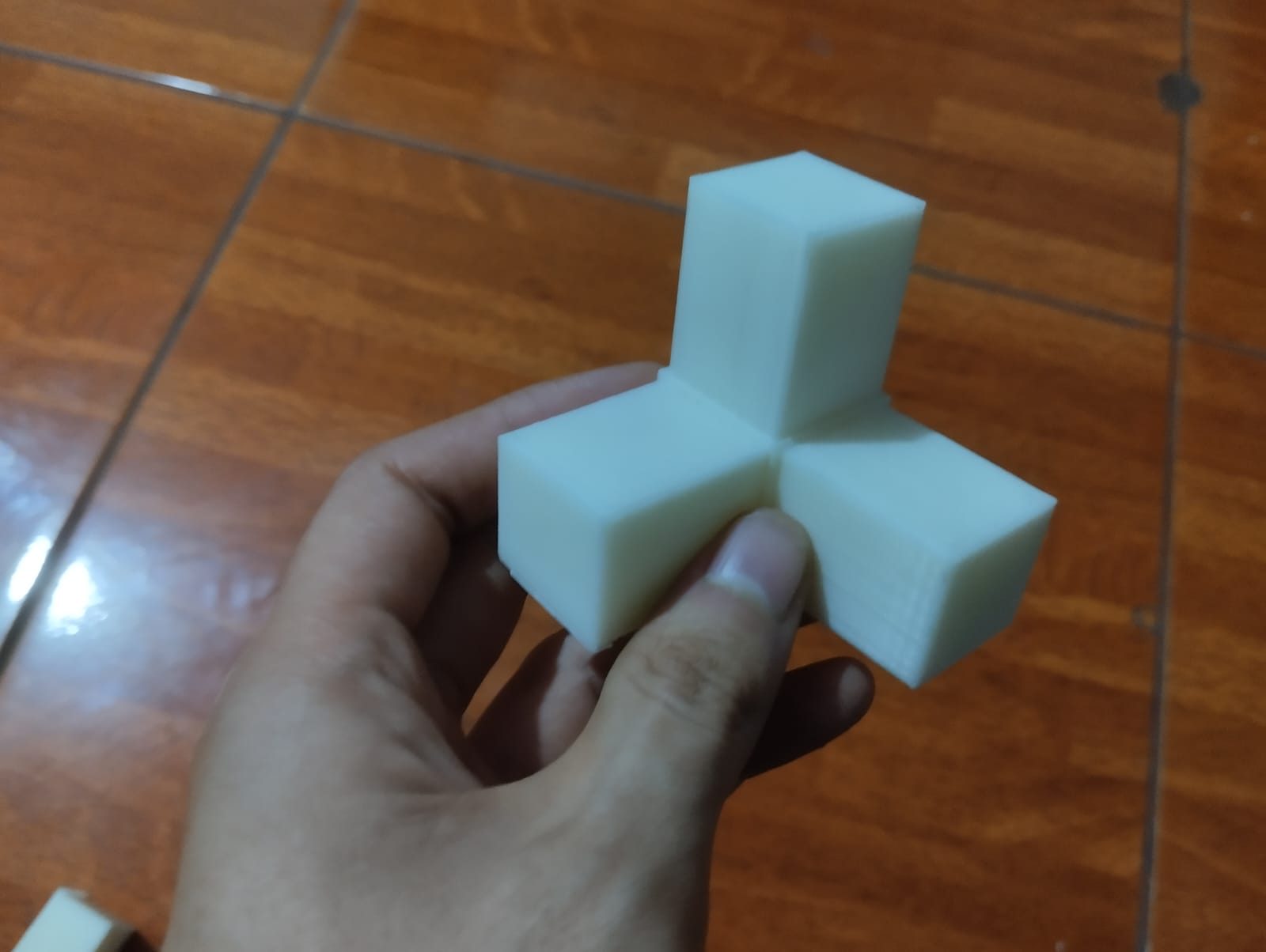
ABS joints:
              #include <SoftwareSerial.h>
                SoftwareSerial BT_Serial(2, 3); // RX, TX

                #define enA 6//Enable1 Pin enA
                #define in1 7 //Motor1   Pin in1

                #define in4 8 //Motor2   Pin in1
                #define enB 9 //Enable2  Pin enB

                #define R_S A1 //ir sensor Right
                #define L_S A0 //ir sensor Left

                int bt_data; // variable to receive data from the serial port
                int Speed = 0;  //pwm motors
                int num = 350; // sensor value that limits the color white from black
                int mode=0;

                void setup(){

                pinMode(R_S, INPUT); // declare if sensor as input
                pinMode(L_S, INPUT); // declare ir sensor as input

                pinMode(enA, OUTPUT); // declare as output for  Pin enA
                pinMode(in1, OUTPUT); // declare as output for  Pin in1

                pinMode(in4, OUTPUT); // declare as output for  Pin in4
                pinMode(enB, OUTPUT); // declare as output for  Pin enB

                Serial.begin(9600); // start serial communication at 9600bps
                BT_Serial.begin(9600);
                delay(500);
                }


                void loop(){

                if(BT_Serial.available() > 0){  //if some date is sent, reads it and saves in state
                bt_data = BT_Serial.read();
                if(bt_data > 20){Speed = bt_data;}
                }

                     if(bt_data == 8){mode=1; Speed=100;} //Auto Line Follower Command
                else if(bt_data == 9){mode=0; Stop(0);}    //Manual Android Application Control Command

                if(mode==0){
                //===============================================================================
                //                          Key Control Command
                //===============================================================================
                     if(bt_data == 1){forword(Speed); }  // if the bt_data is '1' the DC motor will go forward
                else if(bt_data == 2){backword(Speed);}  // if the bt_data is '2' the motor will Reverse
                else if(bt_data == 3){turnLeft(Speed);}  // if the bt_data is '3' the motor will turn left
                else if(bt_data == 4){turnRight(Speed);} // if the bt_data is '4' the motor will turn right
                else if(bt_data == 5){Stop(0); }     // if the bt_data '5' the motor will Stop


                }else{
                //===============================================================================
                //                          Line Follower Control
                //===============================================================================
                if((analogRead(R_S) < num)&&(analogRead(L_S) < num)){forword(Speed);}  //if Right Sensor and Left Sensor are at White color then it will call forword function
                if((analogRead(R_S) >= num)&&(analogRead(L_S) < num)){turnRight(Speed);}//if Right Sensor is Black and Left Sensor is White then it will call turn Right function
                if((analogRead(R_S) < num)&&(analogRead(L_S) >= num)){turnLeft(Speed);} //if Right Sensor is White and Left Sensor is Black then it will call turn Left function
                if((analogRead(R_S) >= num)&&(analogRead(L_S) >= num)){Stop(0);}     //if Right Sensor and Left Sensor are at Black color then it will call Stop function
                }

                delay(10);
                }

                //===========================================================================
                //                          movements functions
                //===========================================================================

                void forword(int s){  //forword
                analogWrite(enA, s); // Write The Duty Cycle 0 to 255 Enable Pin A for Motor1 Speed
                analogWrite(enB, s); // Write The Duty Cycle 0 to 255 Enable Pin B for Motor2 Speed
                digitalWrite(in1, HIGH); //Right Motor forword Pin
                digitalWrite(in4, HIGH); //Left Motor forword Pin
                }

                void backword( int s){ //backword
                analogWrite(enA, s); // Write The Duty Cycle 0 to 255 Enable Pin A for Motor1 Speed
                analogWrite(enB, s); // Write The Duty Cycle 0 to 255 Enable Pin B for Motor2 Speed
                digitalWrite(in1, LOW);  //Right Motor forword Pin
                digitalWrite(in4, LOW);  //Left Motor forword Pin
                }

                void turnRight(int s){ //turnRight
                analogWrite(enA, s); // Write The Duty Cycle 0 to 255 Enable Pin A for Motor1 Speed
                analogWrite(enB, s); // Write The Duty Cycle 0 to 255 Enable Pin B for Motor2 Speed
                digitalWrite(in1, LOW);  //Right Motor forword Pin
                digitalWrite(in4, HIGH); //Left Motor forword Pin
                }

                void turnLeft(int s){ //turnLeftç
                analogWrite(enA,s); // Write The Duty Cycle 0 to 255 Enable Pin A for Motor1 Speed
                analogWrite(enB,s); // Write The Duty Cycle 0 to 255 Enable Pin B for Motor2 Speed
                digitalWrite(in1, HIGH); //Right Motor forword Pin
                digitalWrite(in4, LOW);  //Left Motor forword Pin
                }

                void Stop(int s){ //stop

                analogWrite(enA, s); // Write The Duty Cycle 0 to 255 Enable Pin A for Motor1 Speed
                analogWrite(enB, s); // Write The Duty Cycle 0 to 255 Enable Pin B for Motor2 Speed
                digitalWrite(in1, LOW); //Right Motor forword Pin
                digitalWrite(in4, LOW); //Left Motor forword Pin
                }
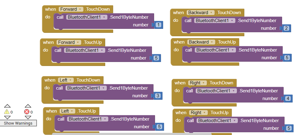
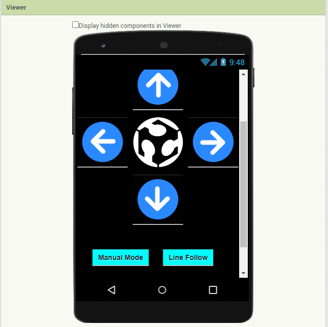
The user interface was designed using App Inventor. We started with a freely accessible base template available in the library and customized the interface to fit the project.
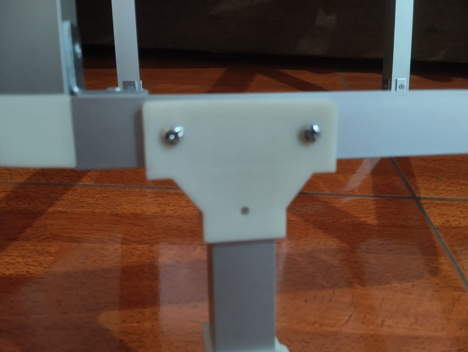
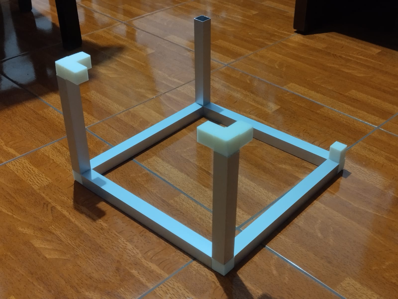
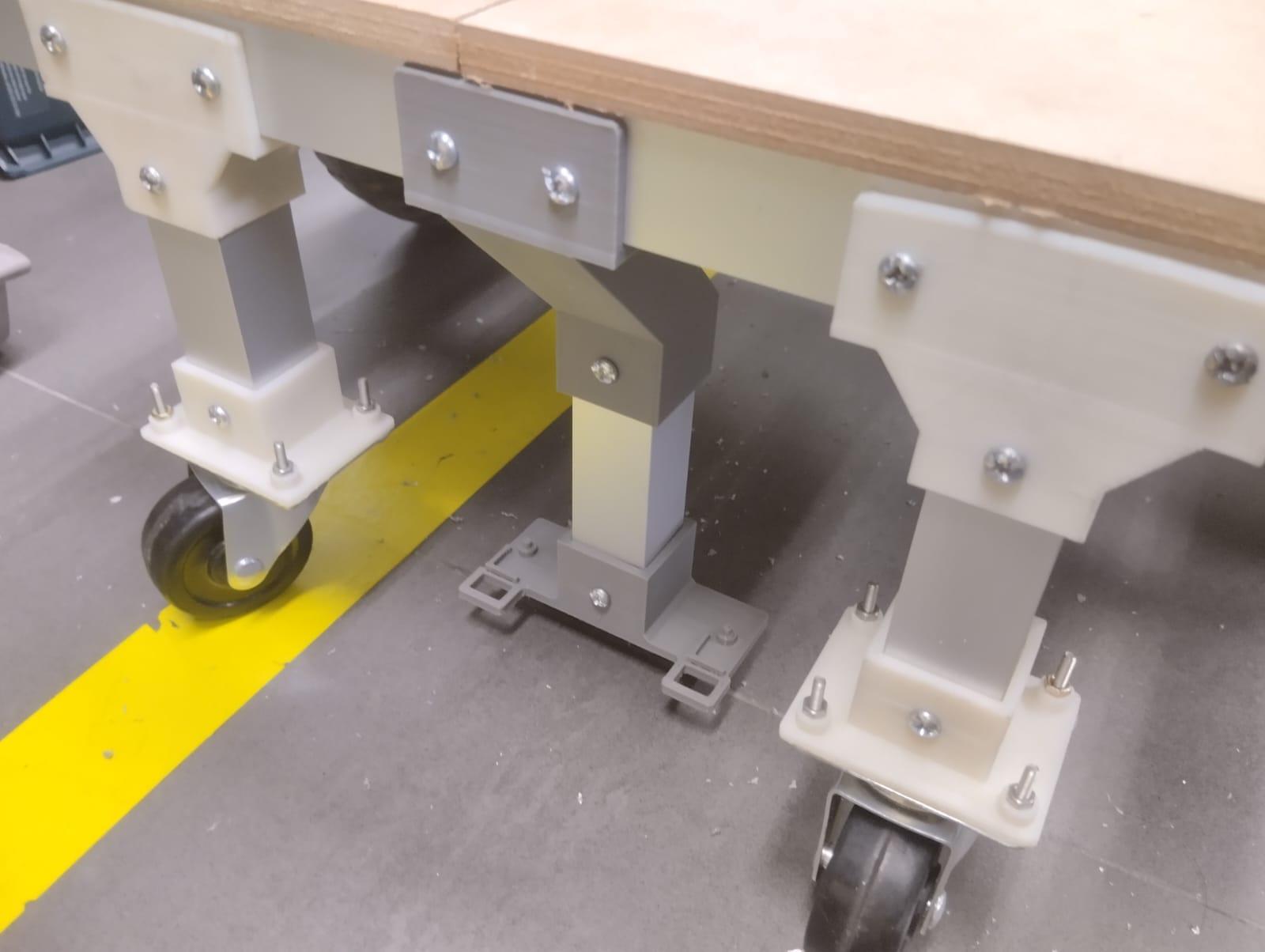
We assembled the aluminum profiles using the 3D printed joints.
We drilled holes in the aluminum to be able to attach the pieces with bolts.
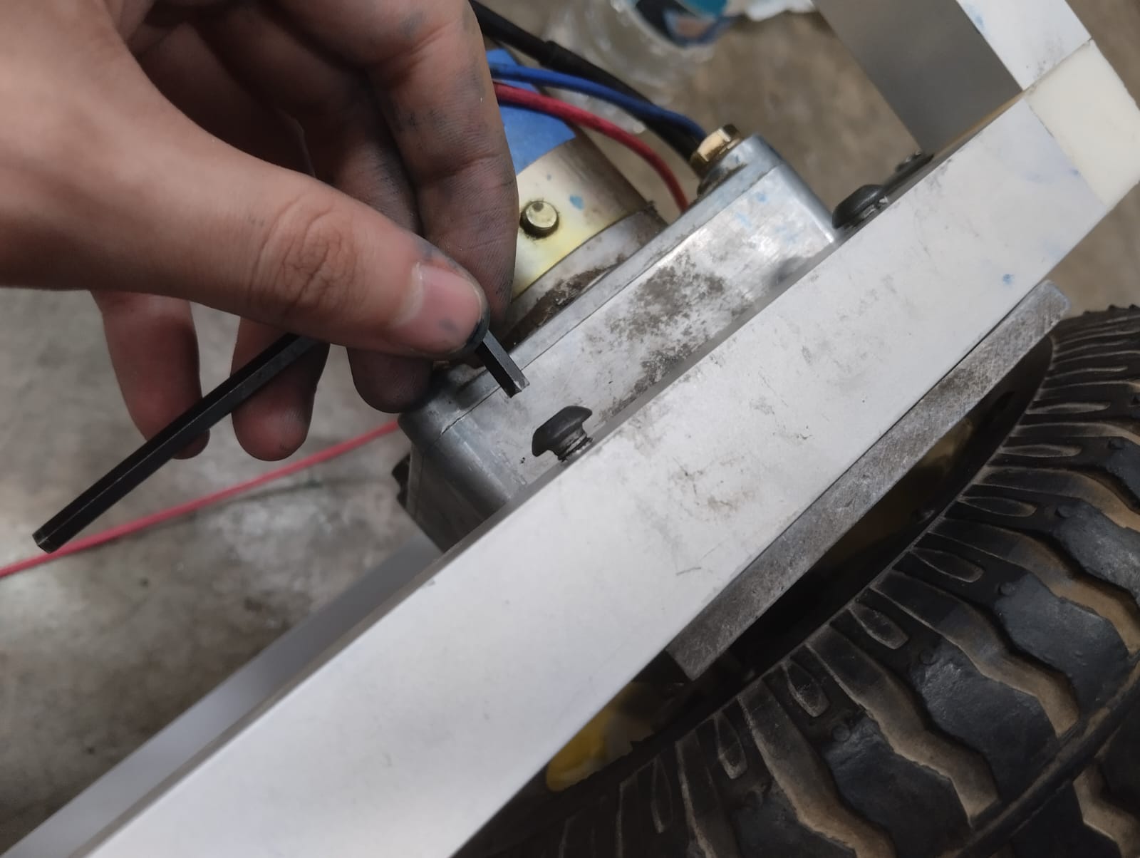
We assembled the pulleys to the profile as shown in the image.
Testing functionality
We assembled the MDF drawers that will be mounted on the aluminum chassis.
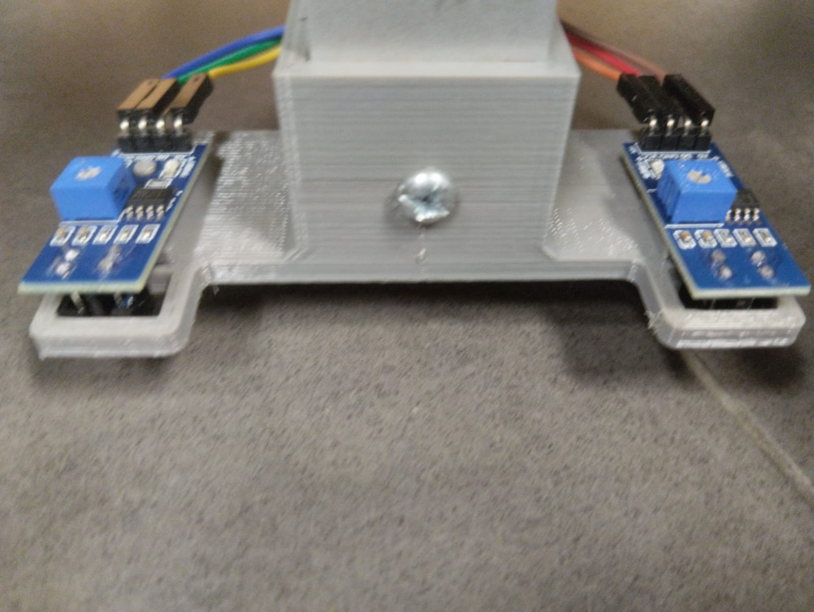
We added the 3D printed piece where the line follower sensors will be mounted.
We added the acrylic cover.
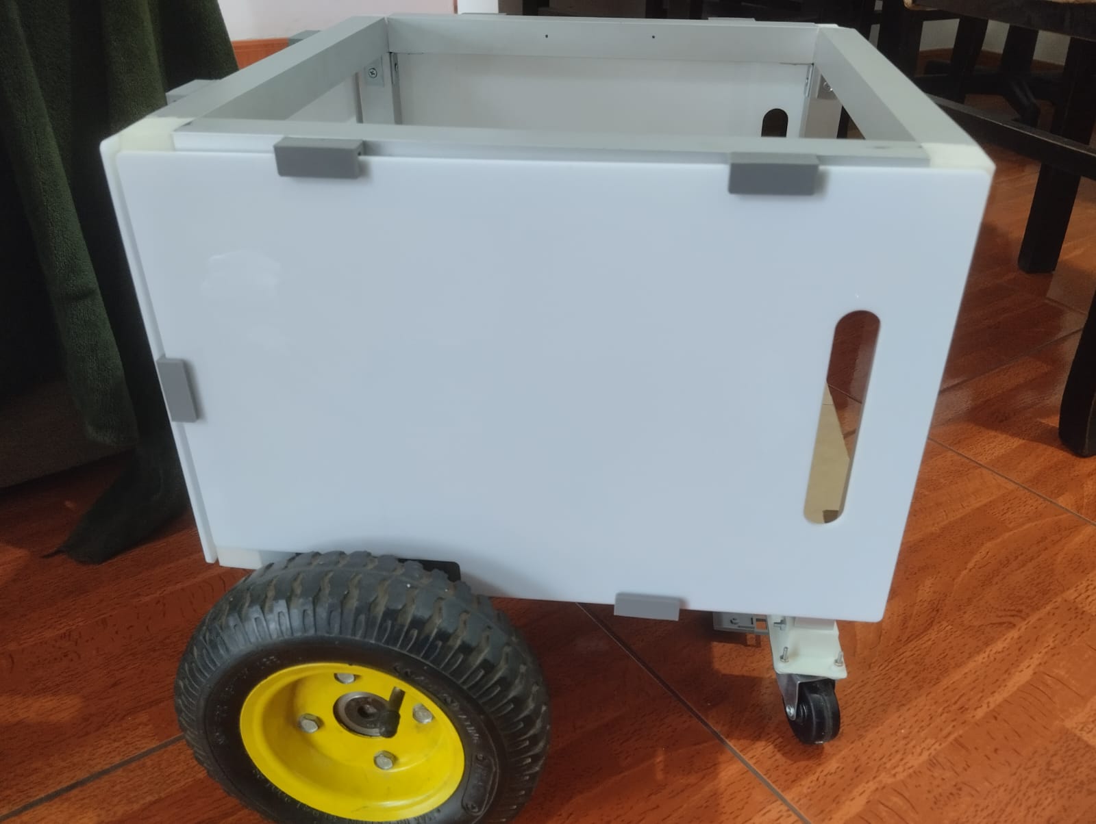
We assemble the mdf structure on the aluminum chassis:
First configuration
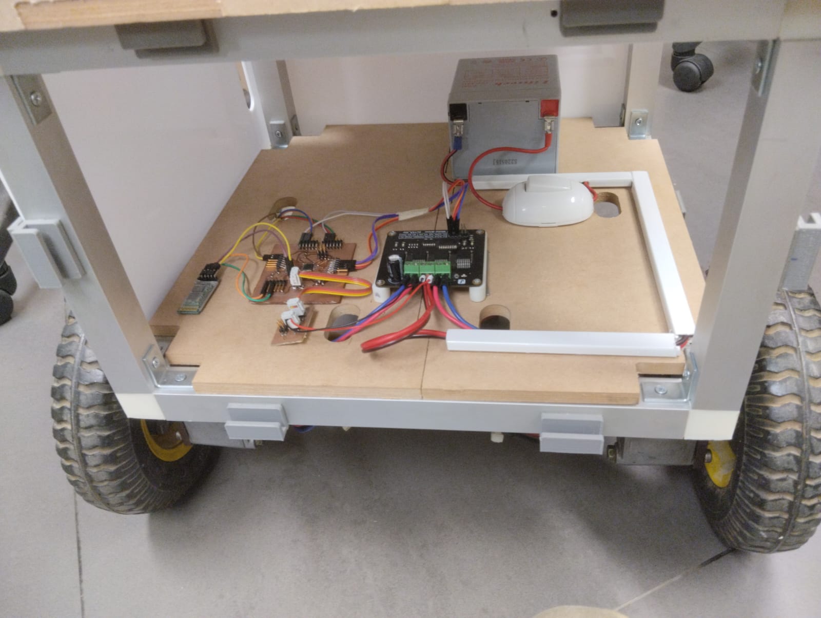
Then I decided to attach the electronics to the base using screws, with a 3 mm MDF square cut by laser and a 3D-printed base for the Bluetooth and driver. The CAD files can be found in the download section.
This is how the final configuration looks.
sensor position
The sensors are placed in the 3D-printed sensor holder. The design allows the sensor to be attached without the need for extra screws.
The robot you are designing will be responsible for transporting the components and tools needed for classes from the laboratory to the classroom autonomously
Andrés Moreno's project, "Fab2D2," is a differential robot designed to assist in moving small objects within a laboratory. The robot incorporates a line follower sensing system for autonomous movement and can carry a maximum of 10 lbs. Whenever the robot moves, it emits a warning sound.The robot operates in two modes: firstly, the "AUTONOMOUS MODE" where it follows a black line. When the robot encounters a cross, it stops for five seconds, allowing people to place or remove objects. You can find more information about this well-documented project, which serves as a guide, at the following link, this was the most similar project i could found, what its different is that the design of my robot allows to transport more things.
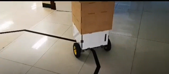
The robot manages to go from point A to B following the line carrying the components. Then we can include the performance of autonomous navigation and the ability to safely transport components and tools.