Computer_Cutting
🖥🖥🖥✂✂✂✂
Group assignment
Group assignement: characterize your lasercutter’s focus, power, speed, rate, kerf, joint clearance and types can be found on our fablab website.
Ok…As I always say, the first thing is the design.
During this week, our goal is to materialize the logo that we created last week with the Inkscape program, using the adhesive vinyl technique. The logo consists of an original and attractive design that represents the identity of our project.
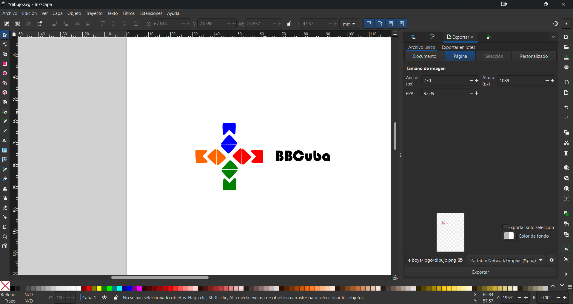
Once the logo file is finished in Inkscape, the next step is to prepare it for vinyl cutting. To do this, we can adjust the size, color and resolution of the logo according to our preferences and the specifications of the material and the cutting machine. For example, we can choose the size of the logo based on the space available on the surface where we want to paste it, the color of the logo based on the contrast we want to create with the background, and the resolution of the logo based on the quality and definition that we want. These adjustments can be easily made from the Inkscape menu, using the scale, fill and stroke, and export options.
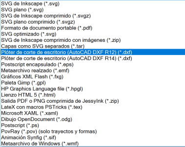
After adjusting the size, color, and resolution of the logo in Inkscape, the next step is to save it as a format compatible with the vinyl cutting program. The most recommended format is DXF (Drawing Exchange Format), which is a vector format that preserves the quality and definition of the logo, and allows it to be easily imported into vinyl cutting software. To save the logo as DXF format, we just have to go to the Inkscape menu, select the save as option, and choose the DXF format from the available options. It is important that the logo is selected before saving, and that it does not have any effects or filters applied that could alter the result. Once the logo has been saved as a DXF format, we can import it into the vinyl cutting program and continue with the process.
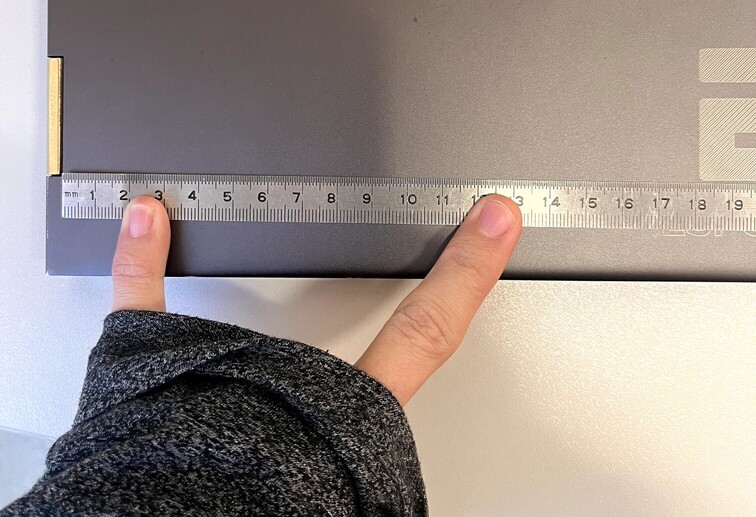
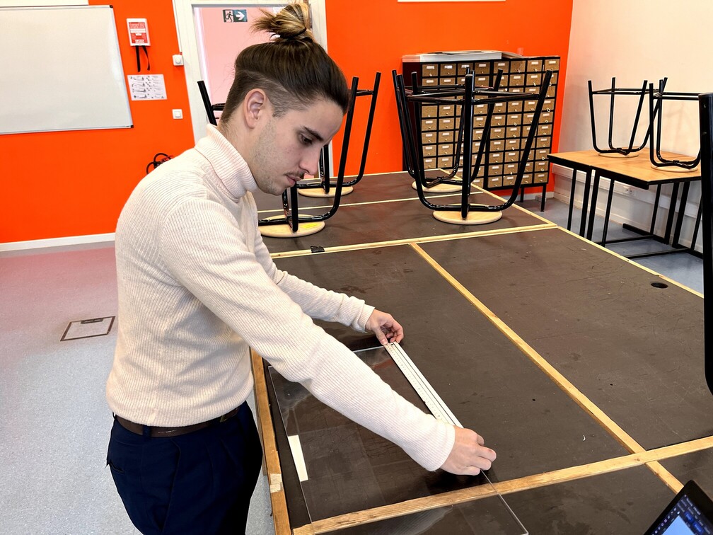
Before adjusting the cutting parameters, it is important that we inspect the surface where we will stick the vinyl and measure it to ensure that the logo is perfect. The surface must be clean, dry and smooth, without dust, grease or irregularities that could affect the adhesion of the vinyl. We must also measure the surface with a ruler or meter, and mark with a pencil or tape the place where we want to place the logo, taking into account symmetry, centering and spacing. These measurements will help us adjust the size of the logo in the cutting program, and to place it correctly on the surface without it being crooked or misaligned.
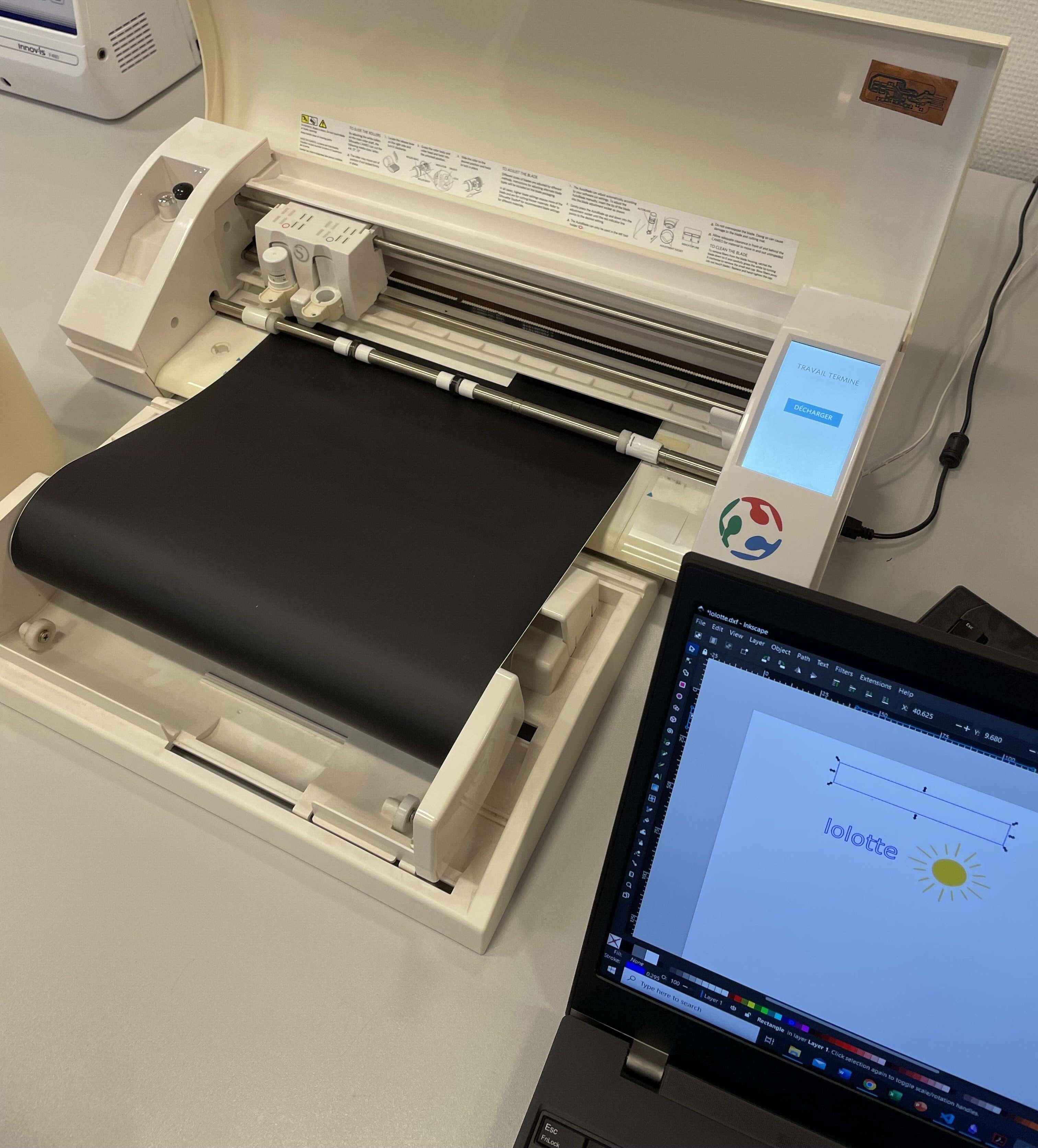
In this photo taken from my colleague Charlotte's websitewe see the vinyl cutter ready to start cutting, once the material has been placed in the cutter, we then load our design in DXF format into the cutter program, the Silhouette Studio and we simply click "send", the machine does the rest.
Now comes the most tense and fun step, which is transferring the logo from the vinyl to the chosen surface. To do this, we need to apply a layer of transfer paper over the cut out logo, which is a special paper that has a soft adhesive that allows you to stick and remove the vinyl without damaging it. We must press the transfer paper well on the logo, using a spatula or a card, so that it adheres to the vinyl and covers it completely. Next, we must peel off the transfer paper carefully, lifting the logo from the vinyl support and leaving only the cut out outline. Thus, we will have the logo ready to stick it on the surface we want, with the transfer paper as a protector. After rubbing a lot, a lot...
OUR MOMENT HAS COME:
How about we cut something harder?
On this occasion, and whenever possible, we are going to take advantage of this week's practices to advance our final project, which consists of designing and manufacturing a smart buoy that can detect pollution. To do this, we are going to use Inkscape and laser cutting to create a light signal that will be integrated into the buoy and that will illuminate with different frecuency. Thus, we will be able to meet the requirements of the practices, which are to create a design with Inkscape and cut it in acrylic, and at the same time give a practical and creative application to our work.
As all of last week's design was done PARAMETRICALLY in Inventor and you can see the step by step of the design and the parameterization in this link, well this week I will try to try something different. I will do it in two ways.
I will focus only on the dome of the buoy, which is the part that will contain the light signal. To make the dome, I'm going to use laser cutting on a sheet of clear acrylic, and then I'm going to heat bend the acrylic to give it the curved shape. I will make the tube that connects it to the rest of the design in 3D printing, using a water- and sun-resistant material. As it will not yet be the final version of the buoy, I will oversize it a little to work more comfortably and to leave room for the electronic components that will go inside. Well, I have never folded acrylic, I will have to be careful not to burn or break it, and follow the instructions given to me in the workshop.
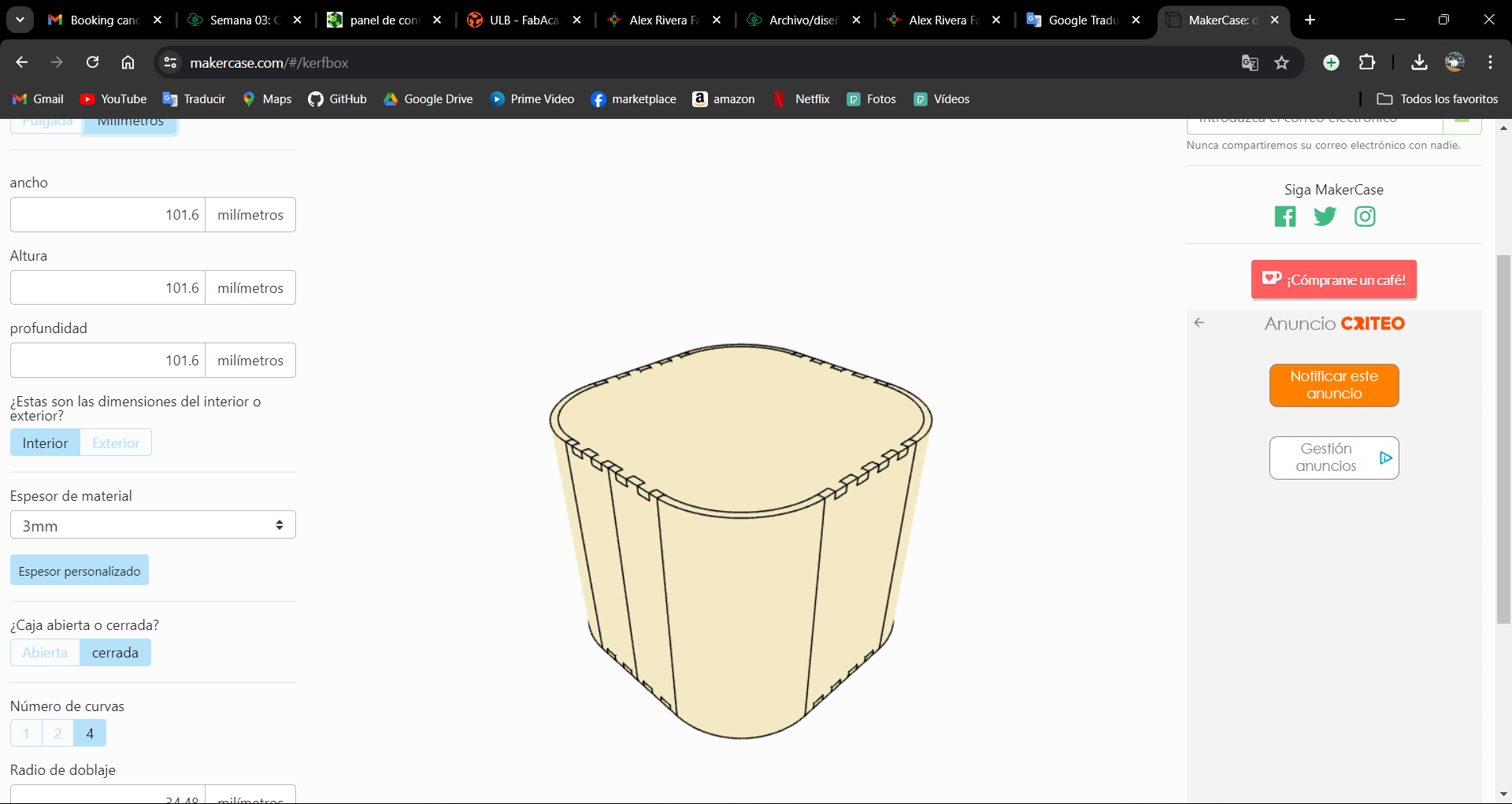
For the design of the box we have many options, we could import the inventor's 2D drawing, we could make a new one in Inkscape, etc. But no, we will use an online tool that will make our work easier. This is the makerCase website, which is a page that allows you to make parametric designs of boxes and other shapes for laser and CNC cutting, in a simple, fast and free way, we can make our design by entering the parameters that our design needs, such as measurements , material, type of joints, etc. The website will generate the plans in SVG or DXF format, ready for cutting.
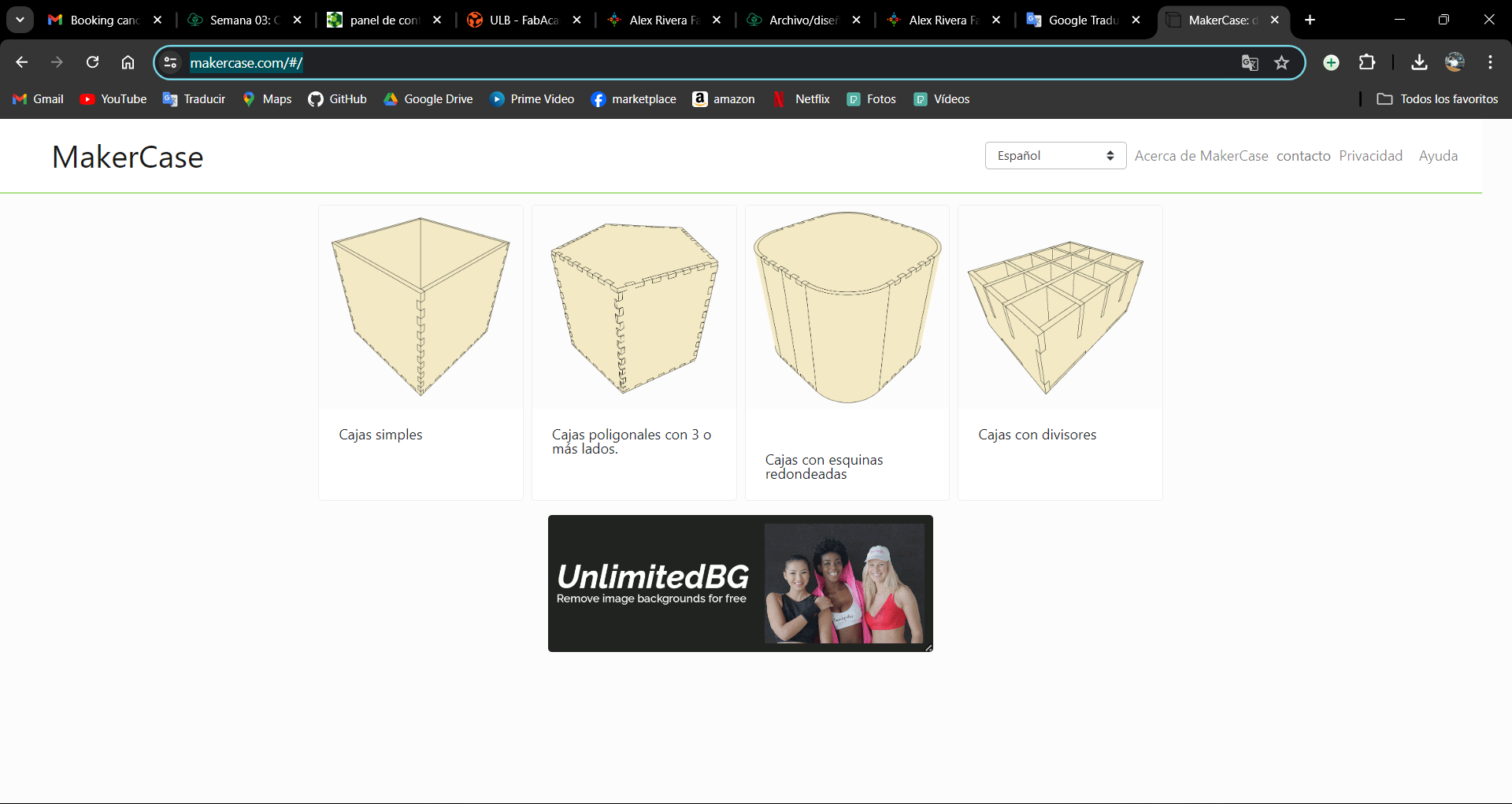
As I said, once the figure is selected, you just have to play with the parameters, dimensions, number of curves, etc... complex designs are not possible, but a practical way to save time when designing boxes.
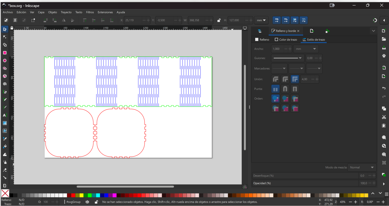
When we finish inserting the data into the makerCase.com website, we can download our file with the parametric design of the acrylic dome. The file will be in SVG or DXF format. We can open the file in Inkscape and make the changes we need, such as adjusting the size, color, resolution or outline of the design, but the most important thing is that the pieces fit perfectly as it will be guaranteed.
The other way
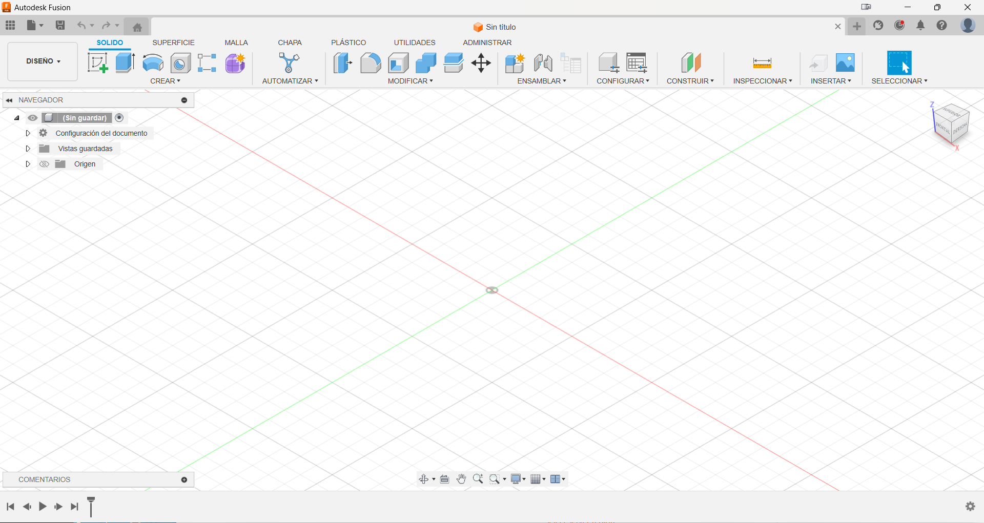
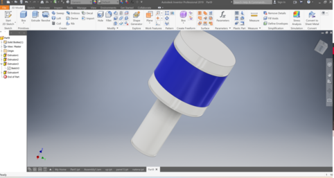
We have already seen the easy way, now I am going to make the figure but in a design program (Fusion 360). This will allow us to have more control over the piece, and I will also make it parametrically.
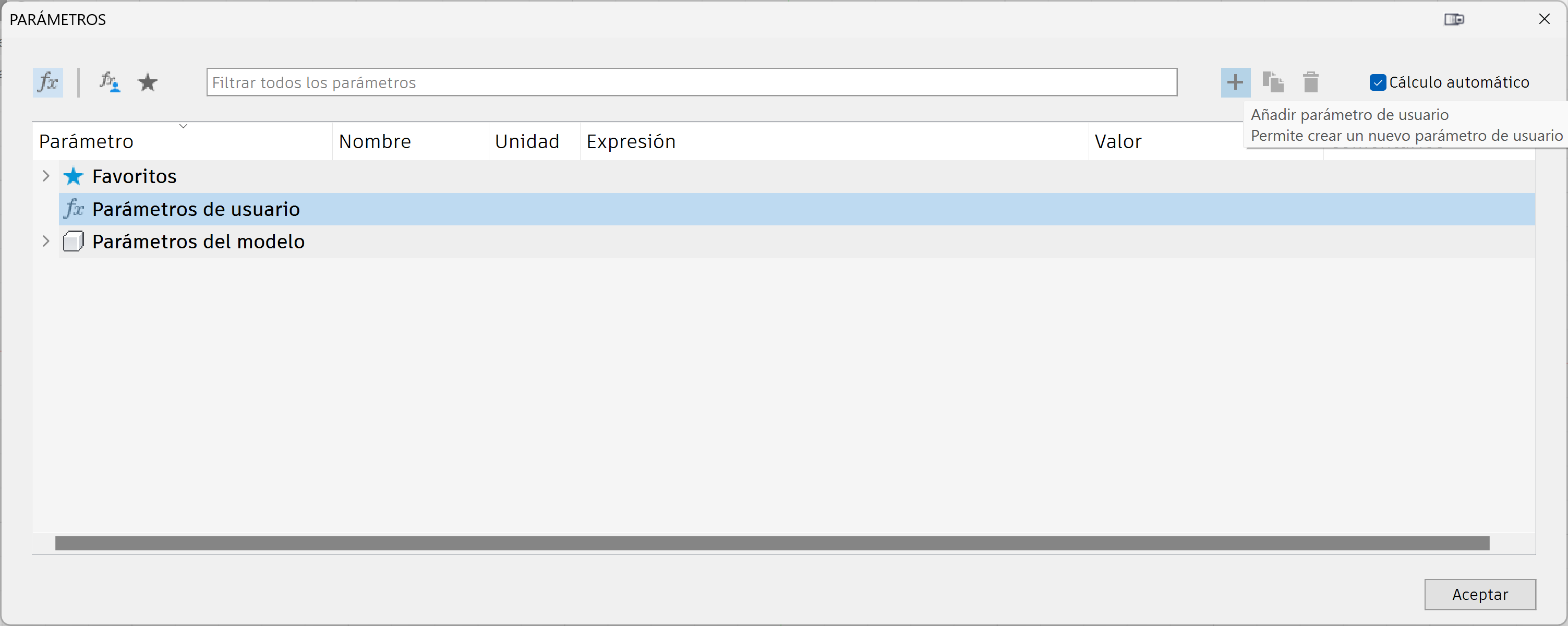
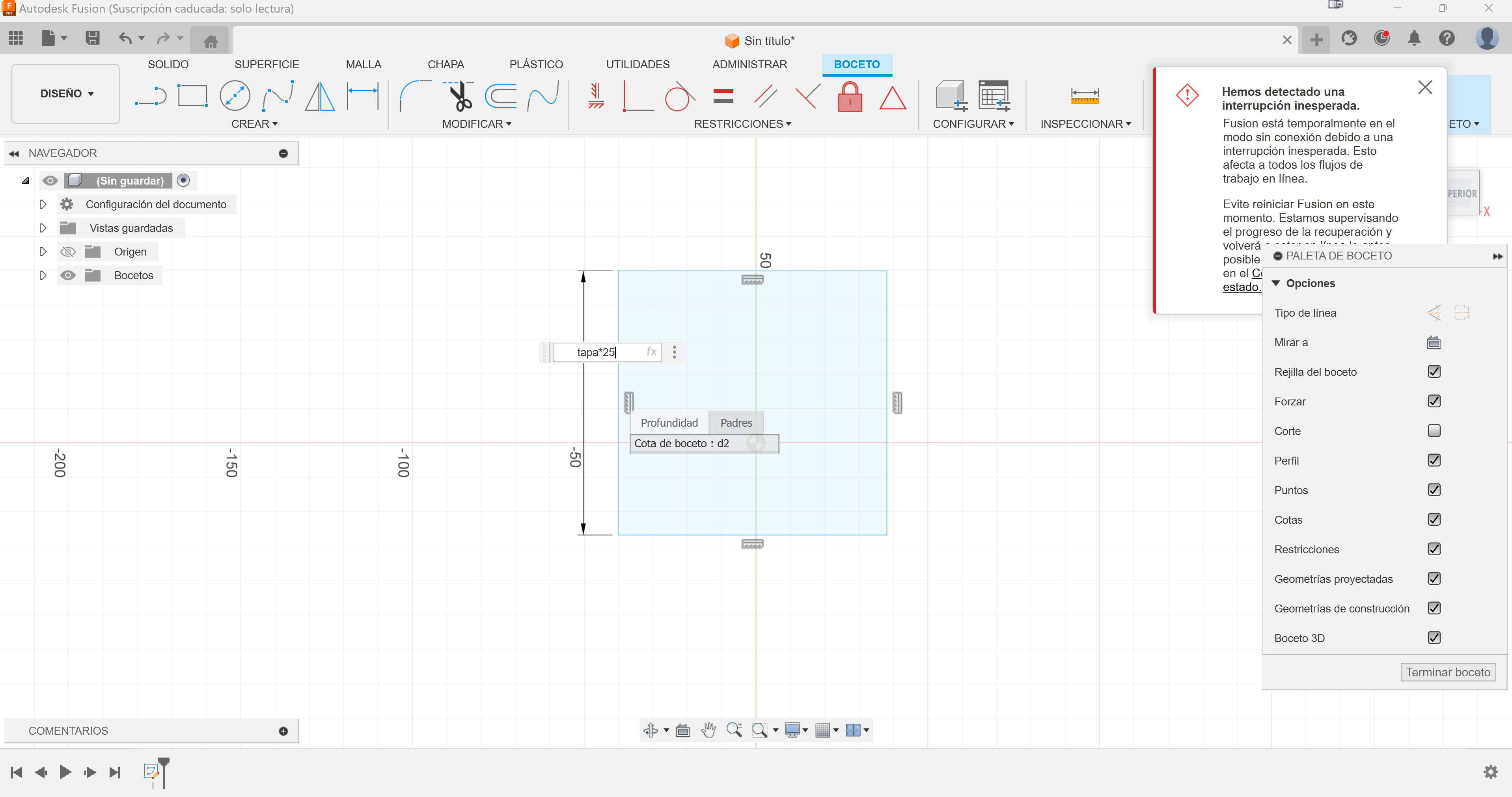
The first thing I will do is create 2 parameters, "tapa" which will be a coefficient without magnitude from which I will make the entire design, and another called "grosor" which is nothing more than the thickness of the material that will be cut, in this case acrylic.
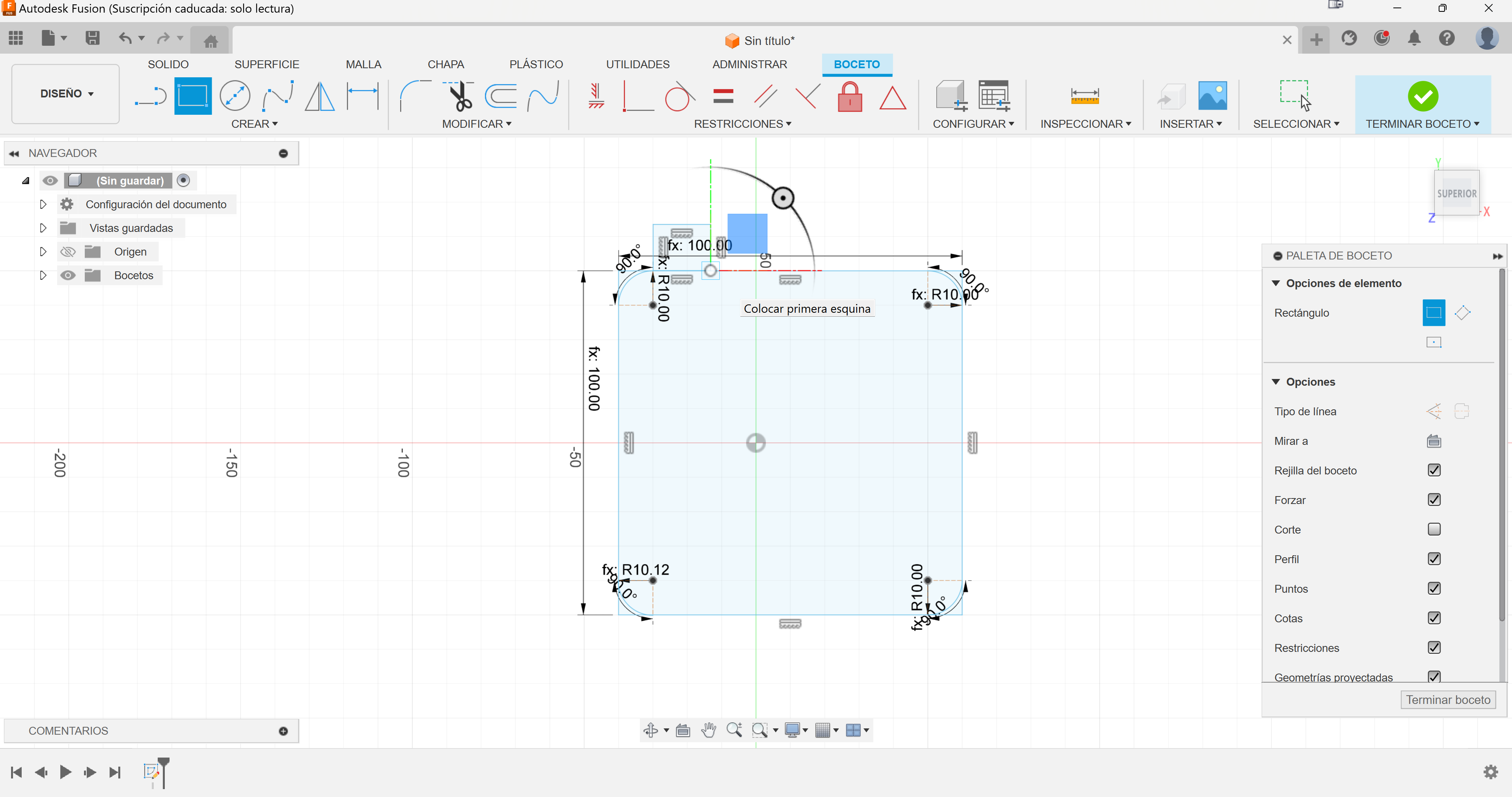
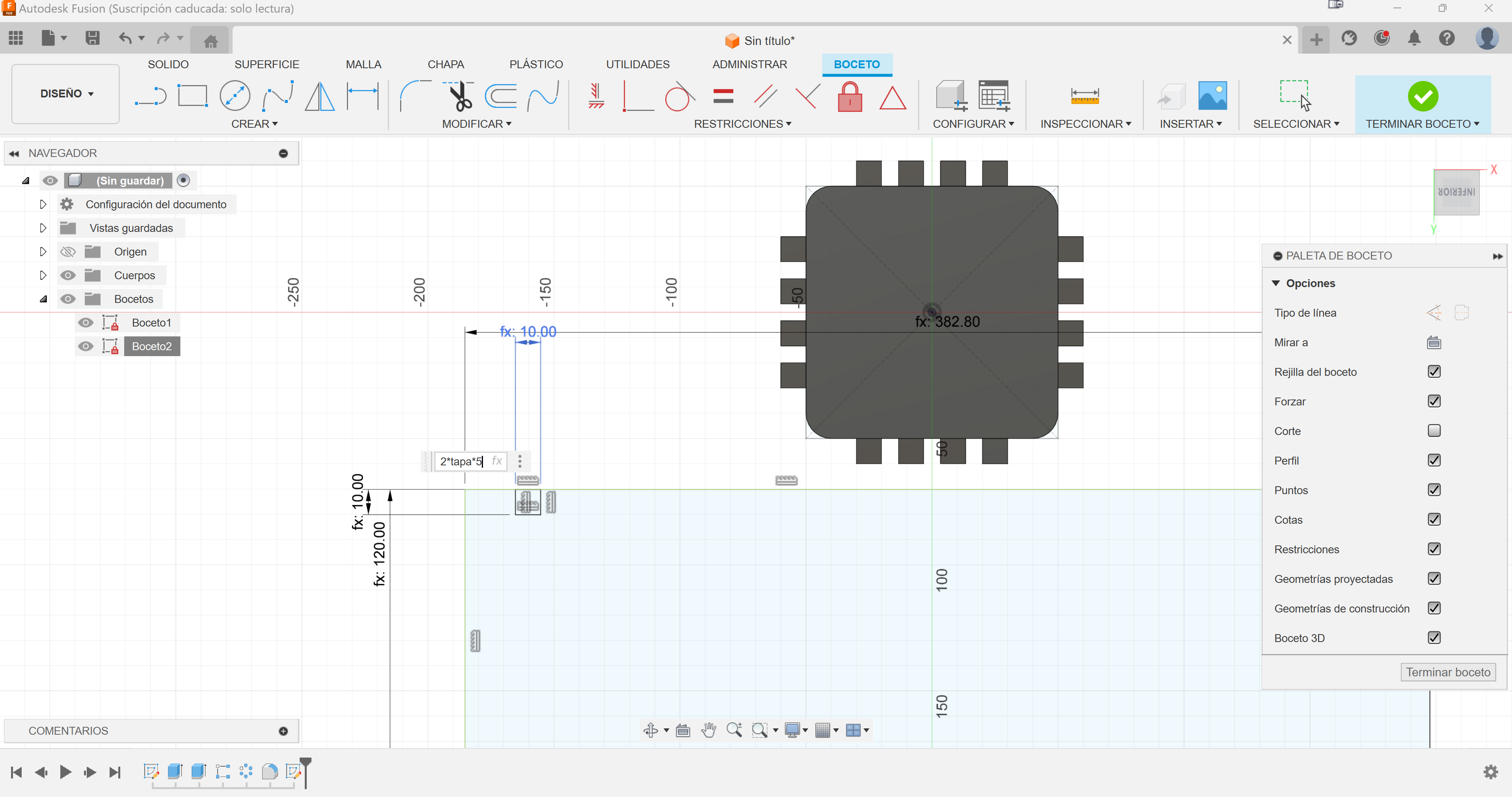
Then, we create a sketch as always, but with the particularity that all the dimensions will be dependent on the parameters of the "tapa".
With the base created, I will now make the "teeth", that is, the adjustment part. Just like in the previous case, I create a smaller rectangle but also dependent on the "tapa". In the photo you can see the arches, but they didn't turn out well, I erased them and will do them later.
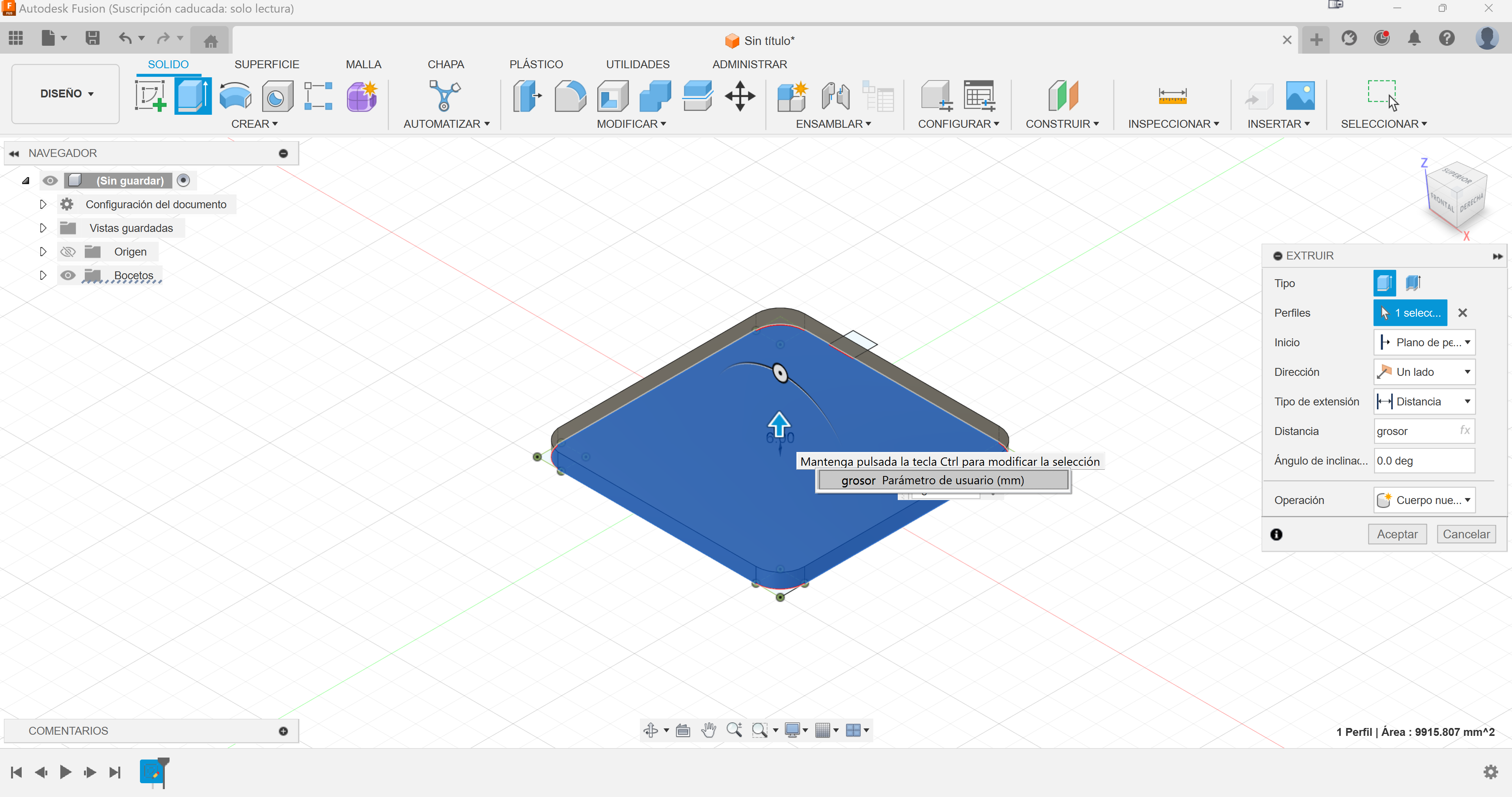
With the sketch created, I will make an extrusion to create the solid, the height of this extrusion will be the "grosor" parameter.
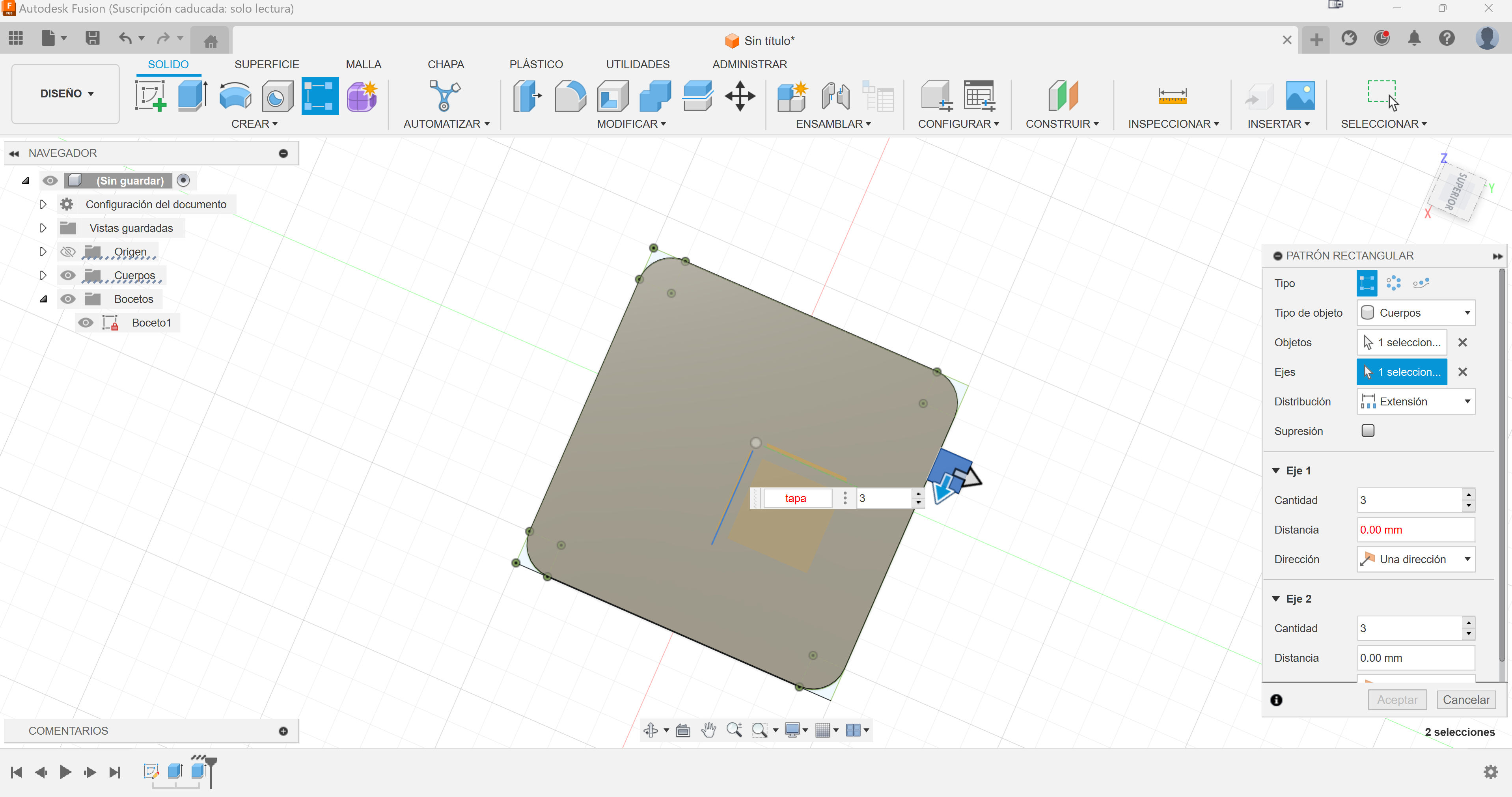
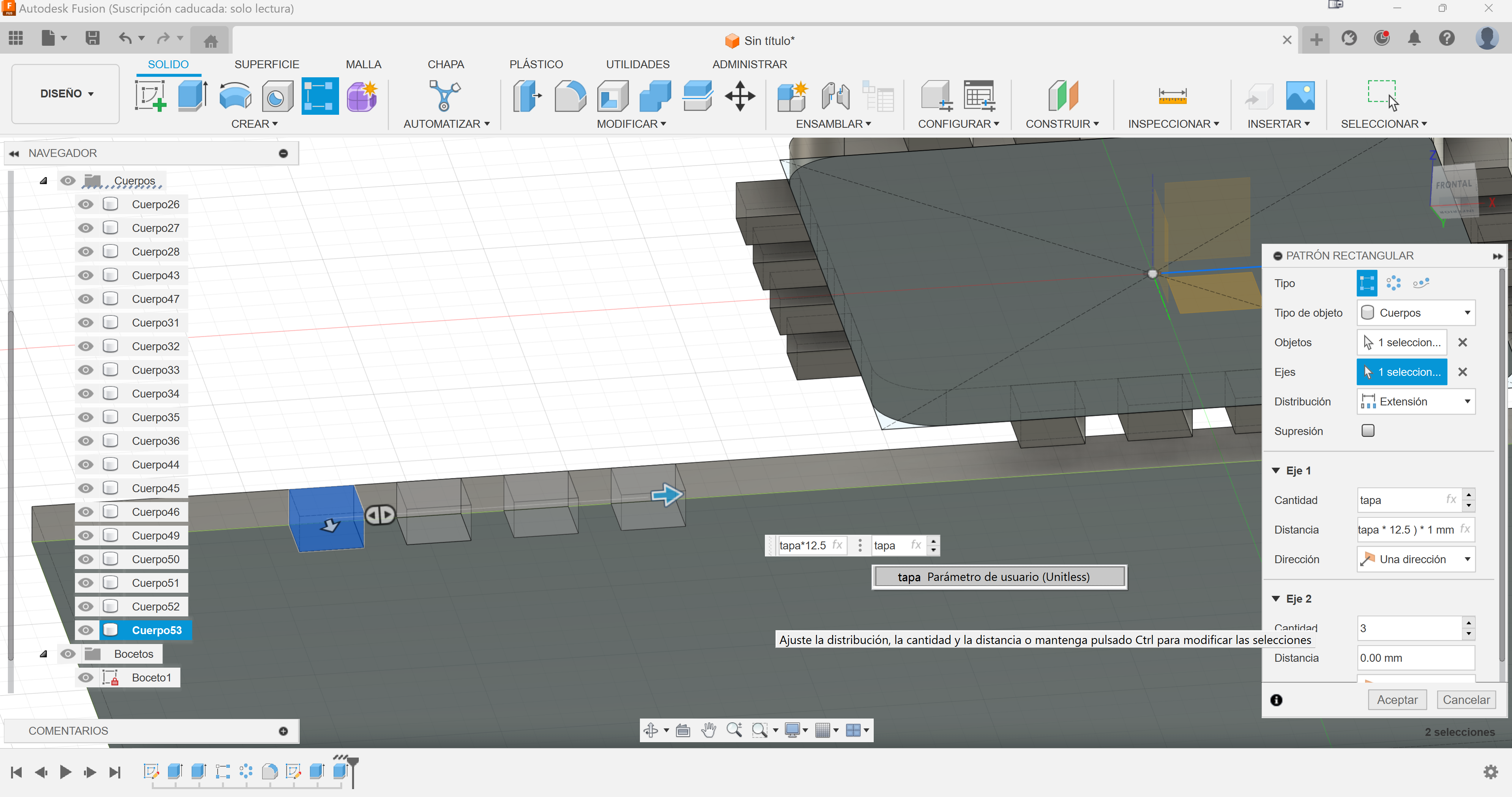
With the pattern tool, we go from having 1 tooth to several, the number of teeth will also be linked to this "cap" dimension.
Once we have the 4 "teeth" ready, we will also go to the pattern tool, but this time it will not be a linear pattern, but a circular one, in this way we can make the 4 stripes of "teeth".
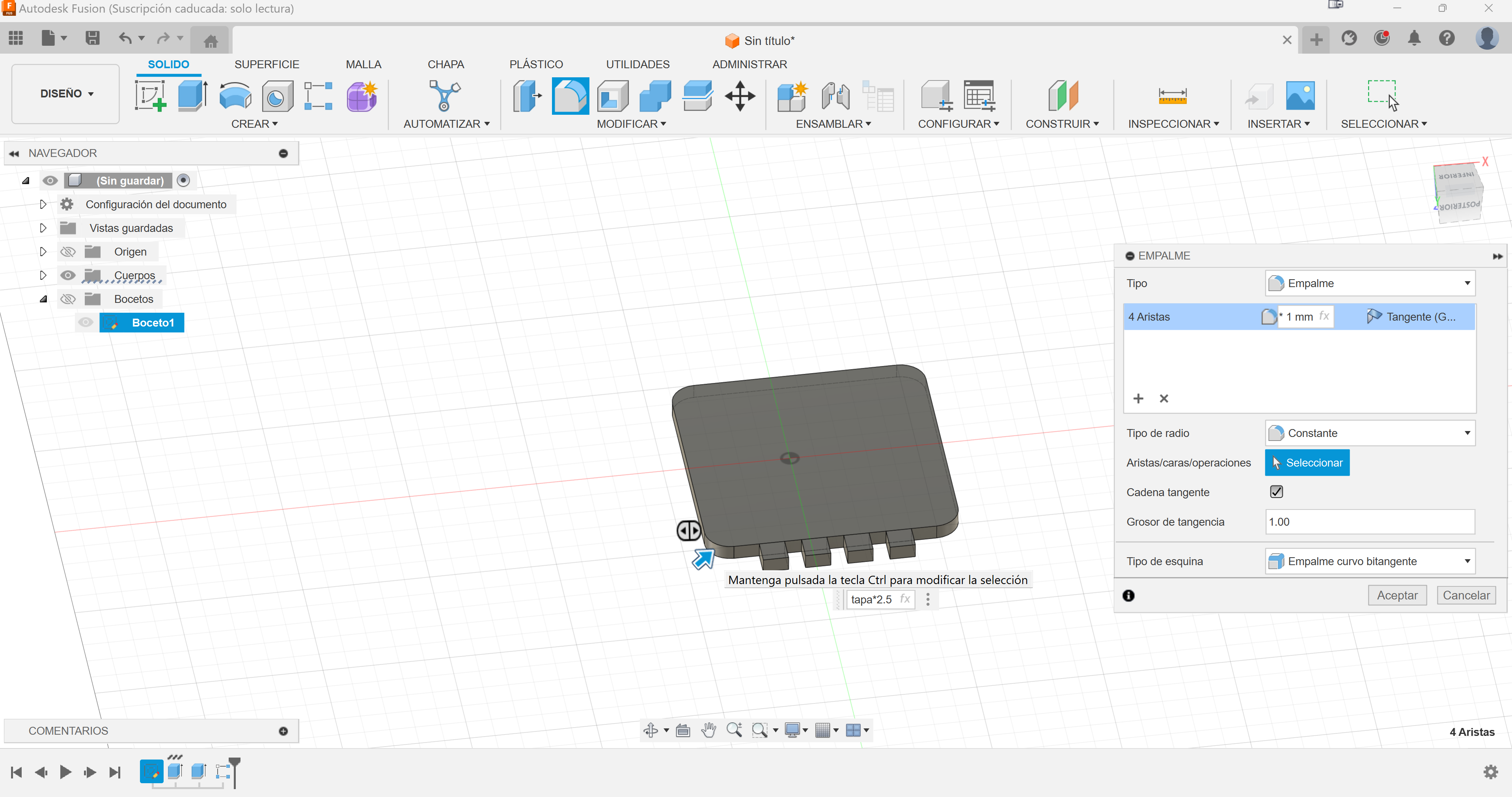
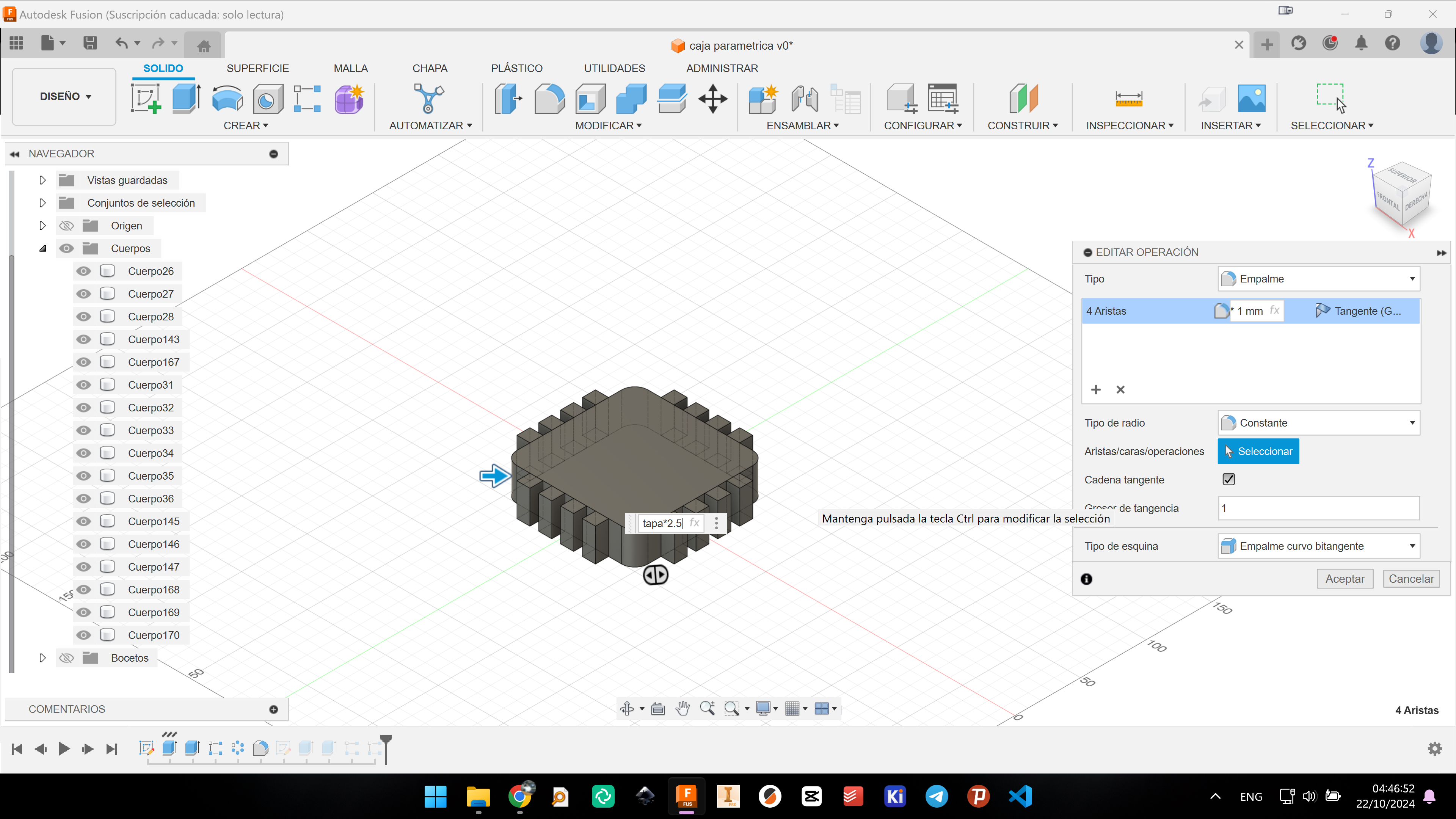
Finally, we will give a small detail to the edge, also parametrically, to relieve the corners. This way it is easier and we do not need the arches.
Now just by changing the "tapa" parameter, the figure changes completely but maintaining the entire structure.
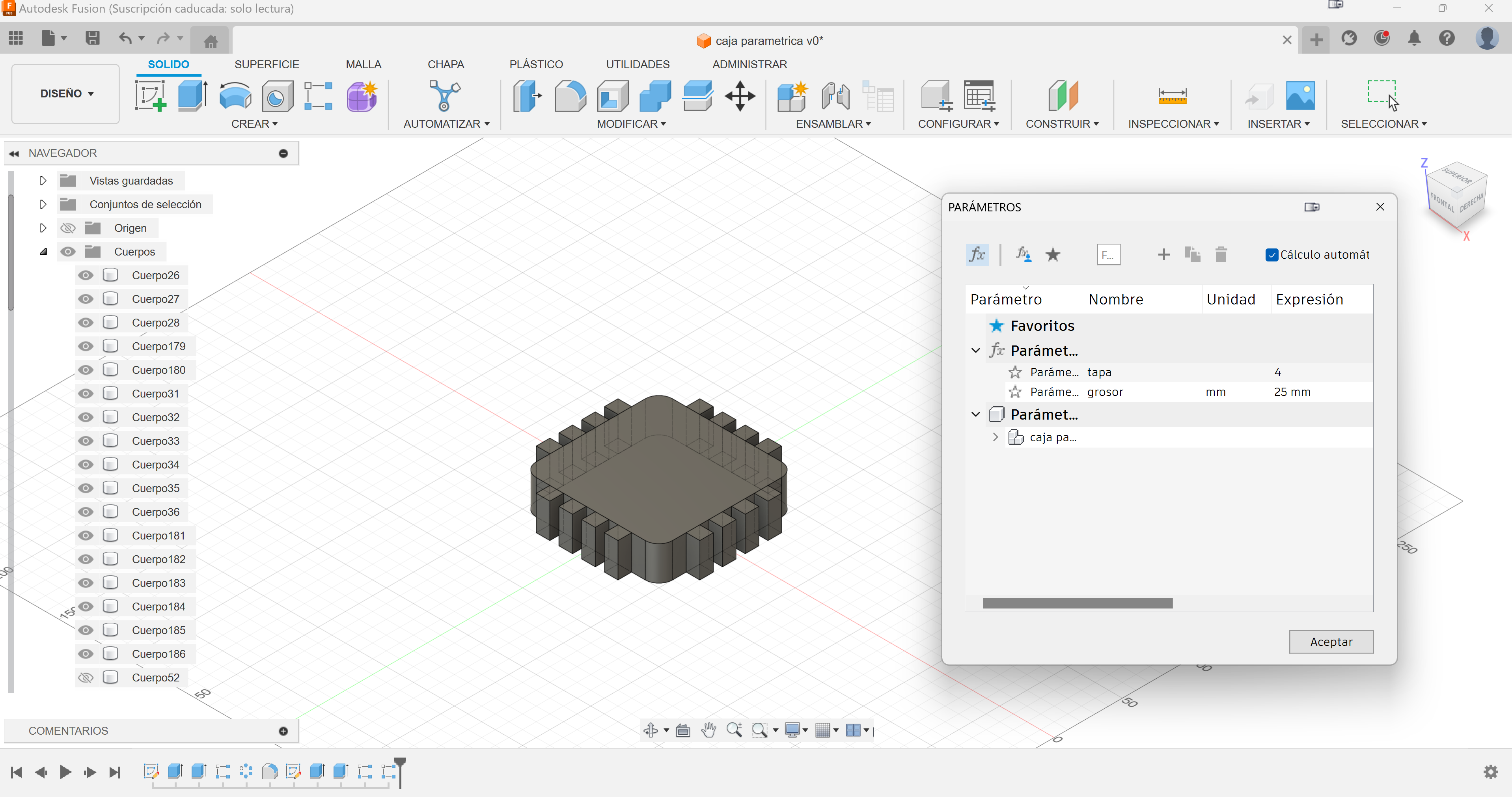
Unfortunately I could only show the changes in the video, since the parameter table does not appear as I could only film one window, even so, this is its view.
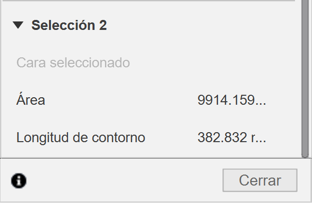
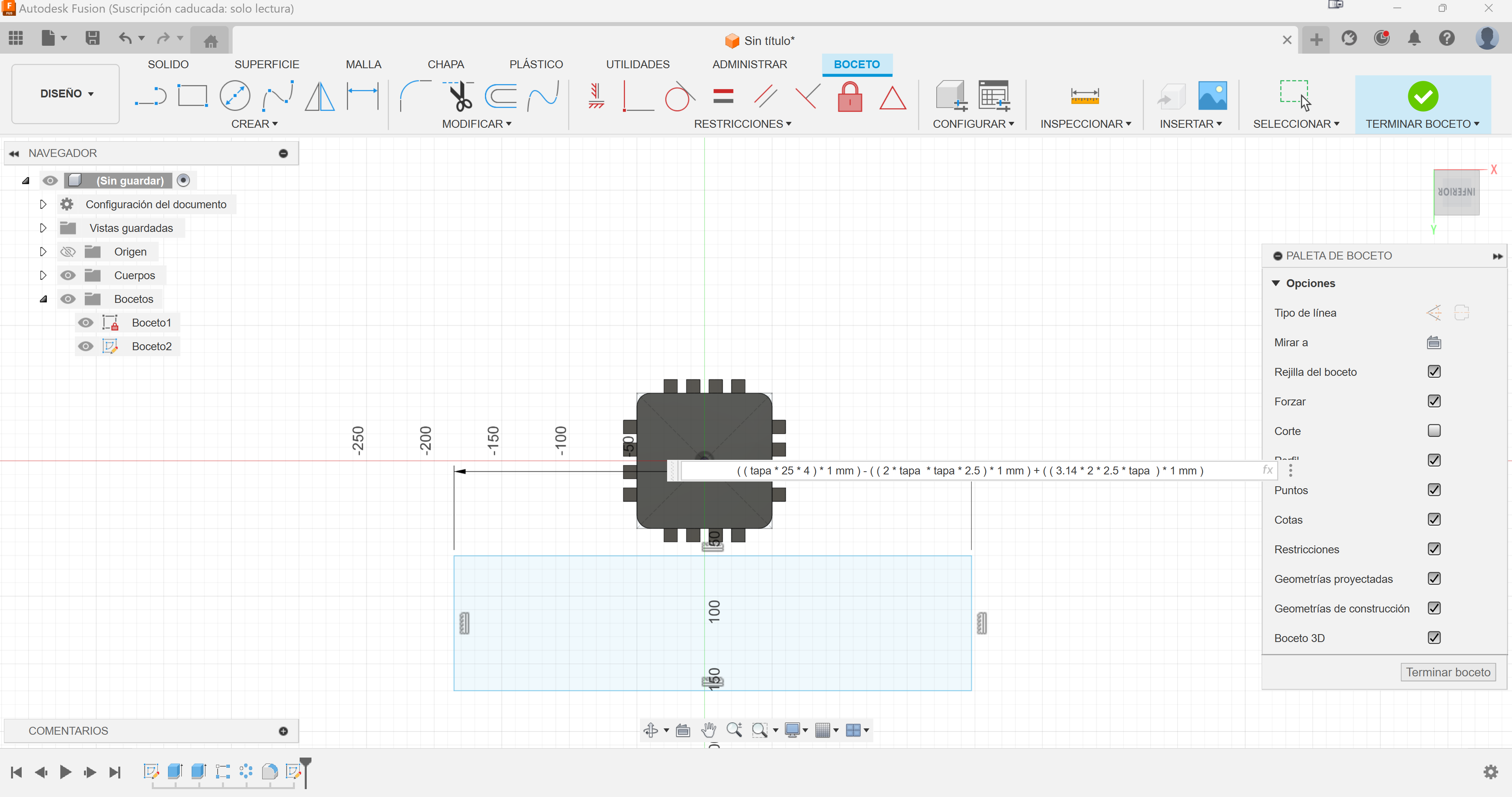
This is the most important part, now that this is ready, we can design the body of the piece, for that, we have to take into account what the length of the body is. The length of the body must match the perimeter of the lid, with the measuring tool, we can see that the perimeter of the lid is a little less than 383.
To do this, you have to take into account that the perimeter of the lid would be four times the length of an edge subtracted from the four corner squares and added to the four arcs, or what would be the same, a circumference of the same radius.
To make the spaces where the teeth will fit, we will do the same but inside the piece.
As in the previous one, we give it an extension for the thickness value and we will use the pattern tool to replicate the slots where the teeth will go.
As seen in the video, the design is ready, by varying the parameters everything changes successfully.
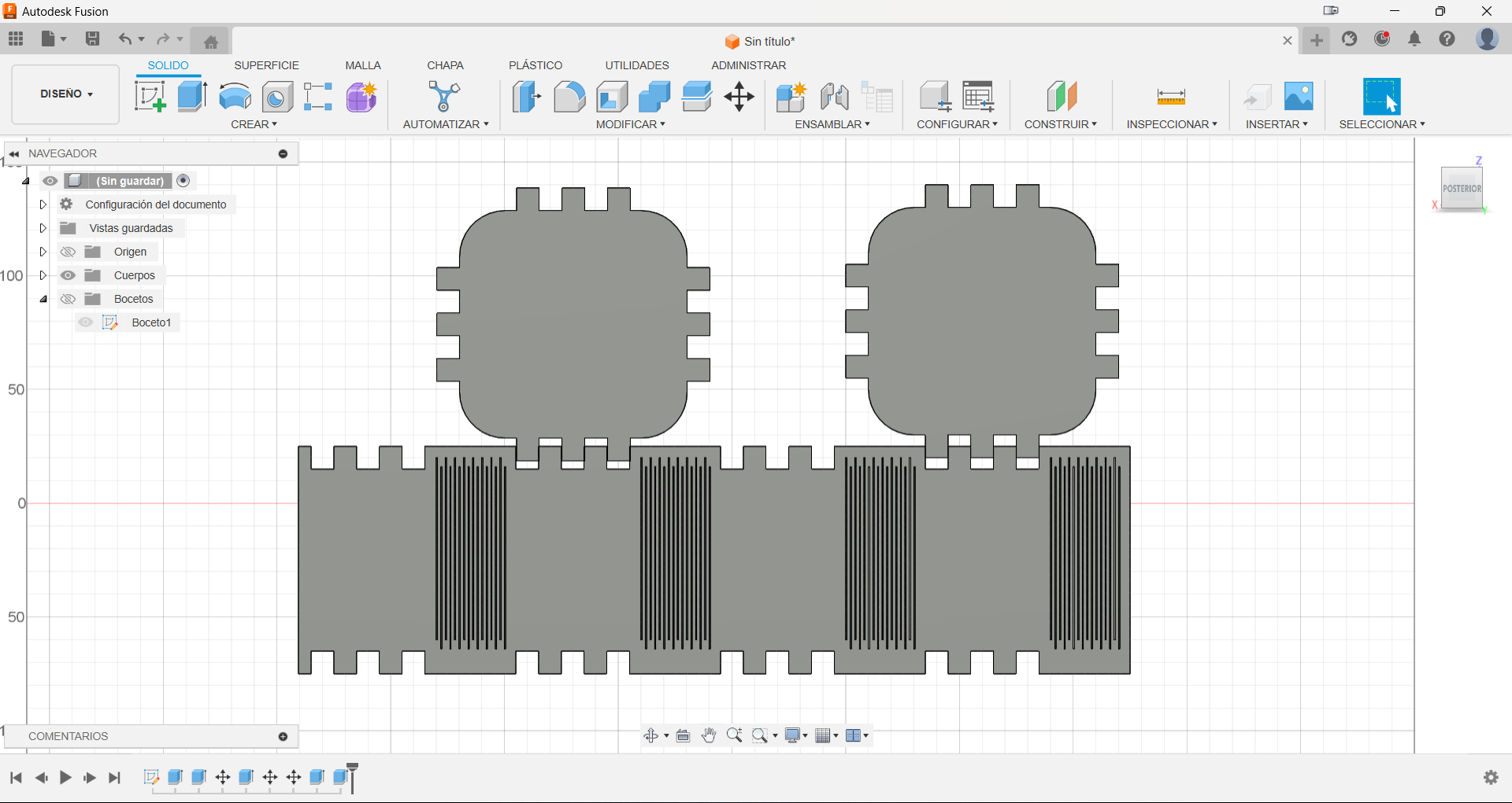
Finally we add color, the details of the lines and copy the lid piece to have 2 units, with that we are ready to cut.
Ready for action
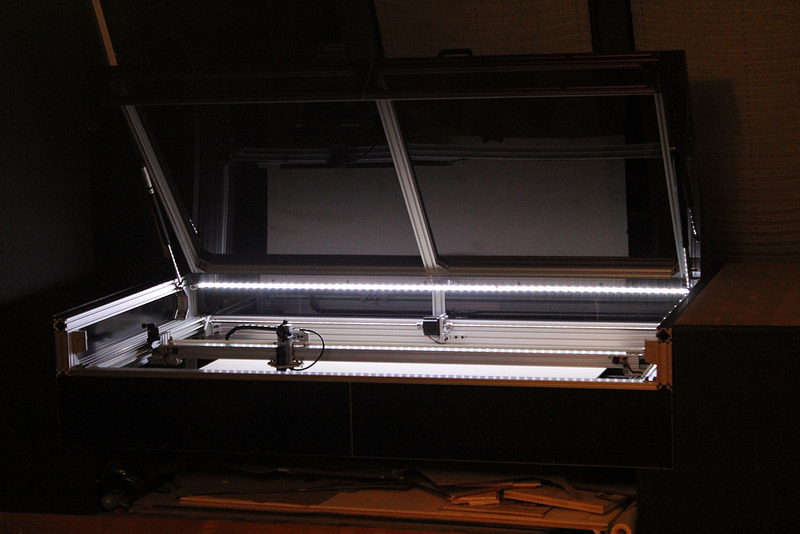
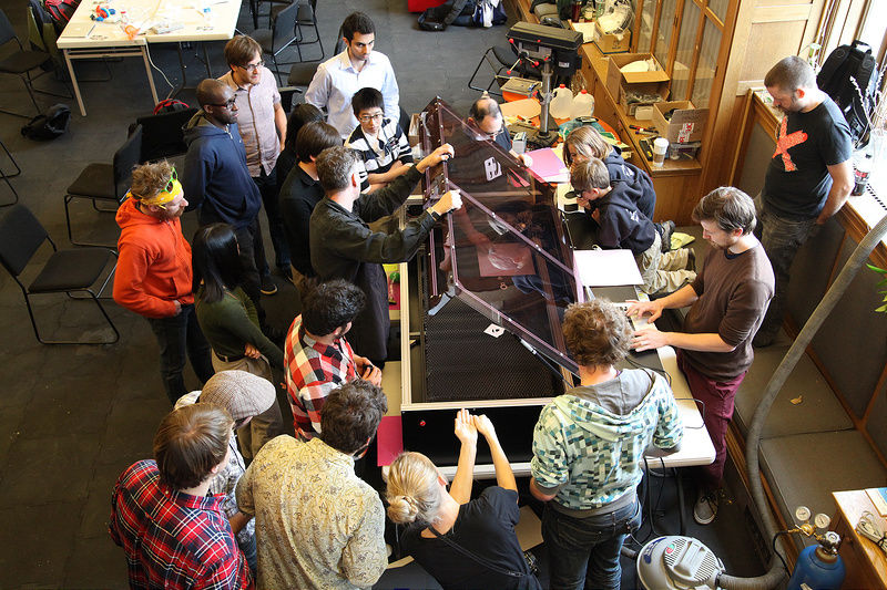
In the ULB Fablab there are 2 laser cutting machines, one professional and another built there, and the latter will be the one we will use to make the cut. It is a Lasersaur type laser, this is a laser cutter with an outstanding price-performance ratio. We designed it to fill the need of makers, designers, architects and researchers who want a safe and highly-capable machine. Unlike others it's open source and comes fully loaded with knowledge to run, maintain, and modify.
The laser I will use for the task will be none other than the one built there: the Lasersaur, which has a working area of 1220x610 mm (48x24”), which is nothing to sneeze at. With a power of 120W @ 10.6um (100W in long duration) that allows us to make deeper cuts in a smaller number of passes with a resolution of 0.1-0.03 mm (240-840 dpi).
To operate the Lasersaur, a very simple web interface is used, although it is certainly a bit limited. In it, you can vary the speed of the laser, the power, the position of the piece to be cut and the number of passes, but it lacks tools such as pattern creation, design rectification or iteration in the passes, elements present in software such as LightBurn.
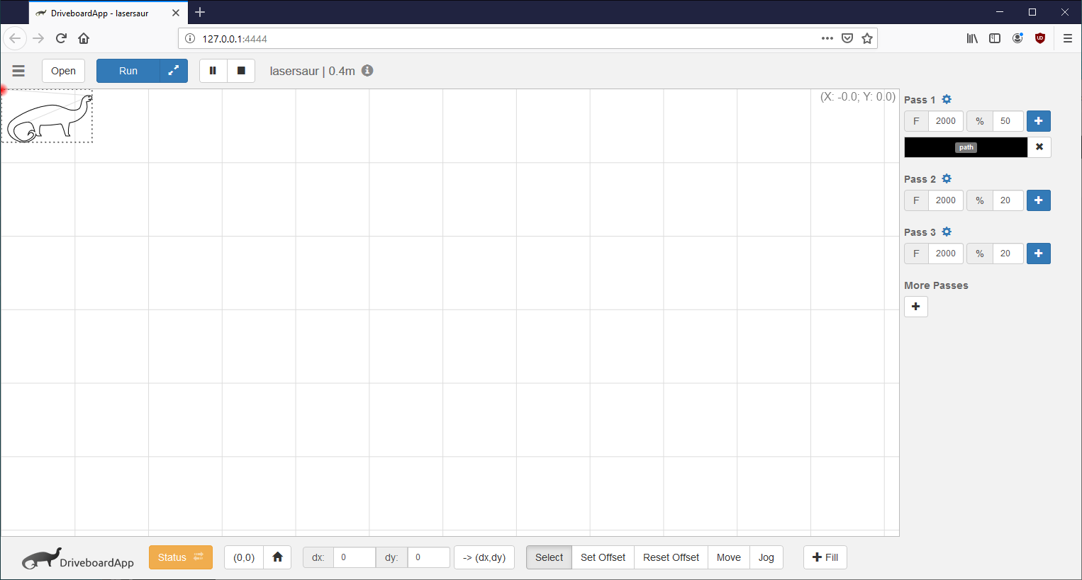
As I said, the interface is quite simple. At the bottom, there are the controls related to the position, the starting point of the cut and the buttons to move the laser head. At the top, there are the buttons to load the pieces and start the cut. Finally, on the side panel, we can see how to adjust the cutting parameters.
.png)
In the side section we adjust the parameters related to cutting: speed and power. Additionally, we can configure different cutting properties for several or the same piece using colors. For example, in the piece I am going to cut, I define two different colors: one for the edges and another for the internal lines; with the objective of increasing the power at the edges for cutting and decreasing it at the center lines, since they are only for bending the acrylic later.
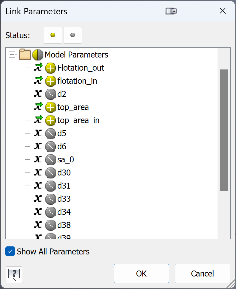
How can we use the parameters of one part in another?.
We adjust the parameters in the laser cutting machine program, which allows us to control the power and speed of the laser depending on the type of material and the thickness. For the cuts that will define the outline, we will use a power of 100W, which is enough to cut through the acrylic without burning or melting it. To crack the sides, which are slots that will help us bend the acrylic with heat, we will use a power of 40W, which is lower than the cutting power so that the laser only marks the acrylic without cutting it completely. In both cases, we will use a speed of 600 mm/min, which is a moderate speed that guarantees a precise and uniform cut. For the focal adjustment, which is the distance between the laser and the acrylic, we will use a piece that the workers of this fablab have provided us, which has a height of 13 mm, which is the optimal measurement for the laser to have the greatest power and definition. Thus, we only have to place the piece on the acrylic and adjust the height of the machine until the laser touches the tip of the piece. In this way, we can simply and quickly calibrate the focal adjustment, without having to use any other tool or measurement.
This is the moment
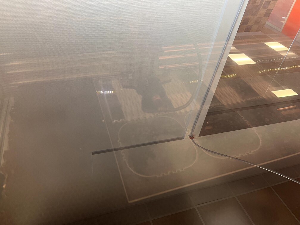
With the pieces cut, the next step is to bend the acrylic to shape the dome of our project. The logic is simple: we apply hot air over the slots we have made with the laser, and carefully bend the acrylic until we achieve the desired angle. But the execution is more complicated than it seems, since acrylic is a delicate material that can burn, break or deform if not handled correctly. I had to fold and unfold many times, trying to make sure the edges matched and the dome was symmetrical and wrinkle-free. Even so, the result is questionable, and it is clear that I am not an expert in this technique.
Result
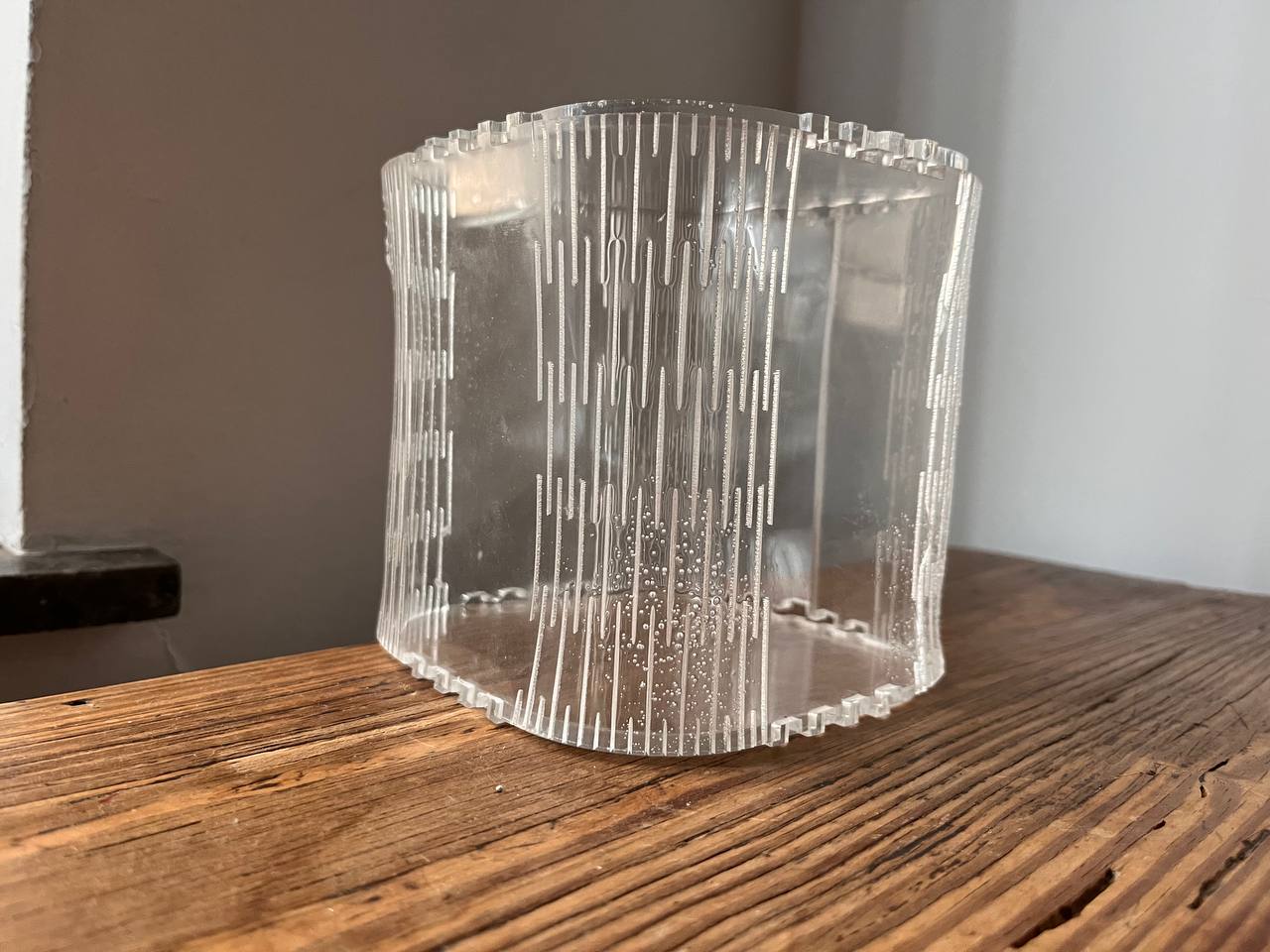
The result is far from being satisfactory, in many places the acrylic made bubbles and in others small cracks were created, anyway...I have to keep trying.In the following link are the design files.
Last piece
Finally, we are going to cut some small pieces from which several larger pieces can be assembled. I was searching on the web and found that there are these kinds of acrylic balls and rubber bands, so I will do that.
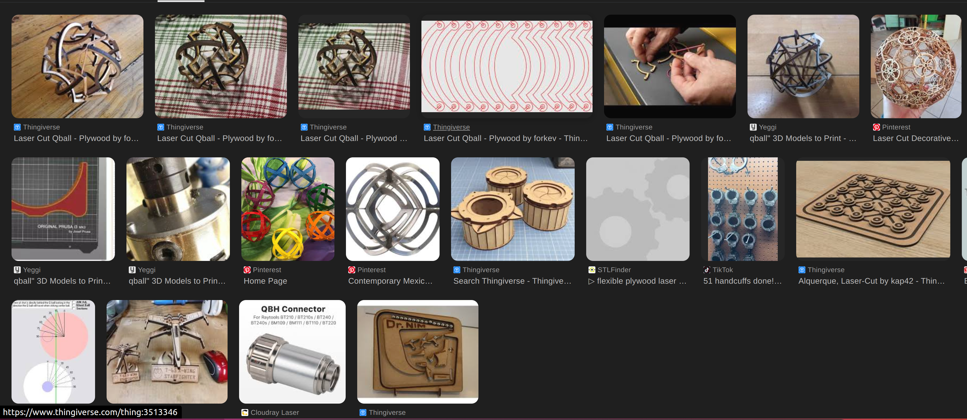
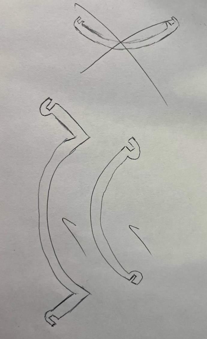
There are many versions on the internet, larger or smaller, I will design a medium one, with 2 types of pieces, 12 in total, with which you can put together several decorative pieces and of course, a ball, which is the objective.It's ugly but it transmits. Hehe
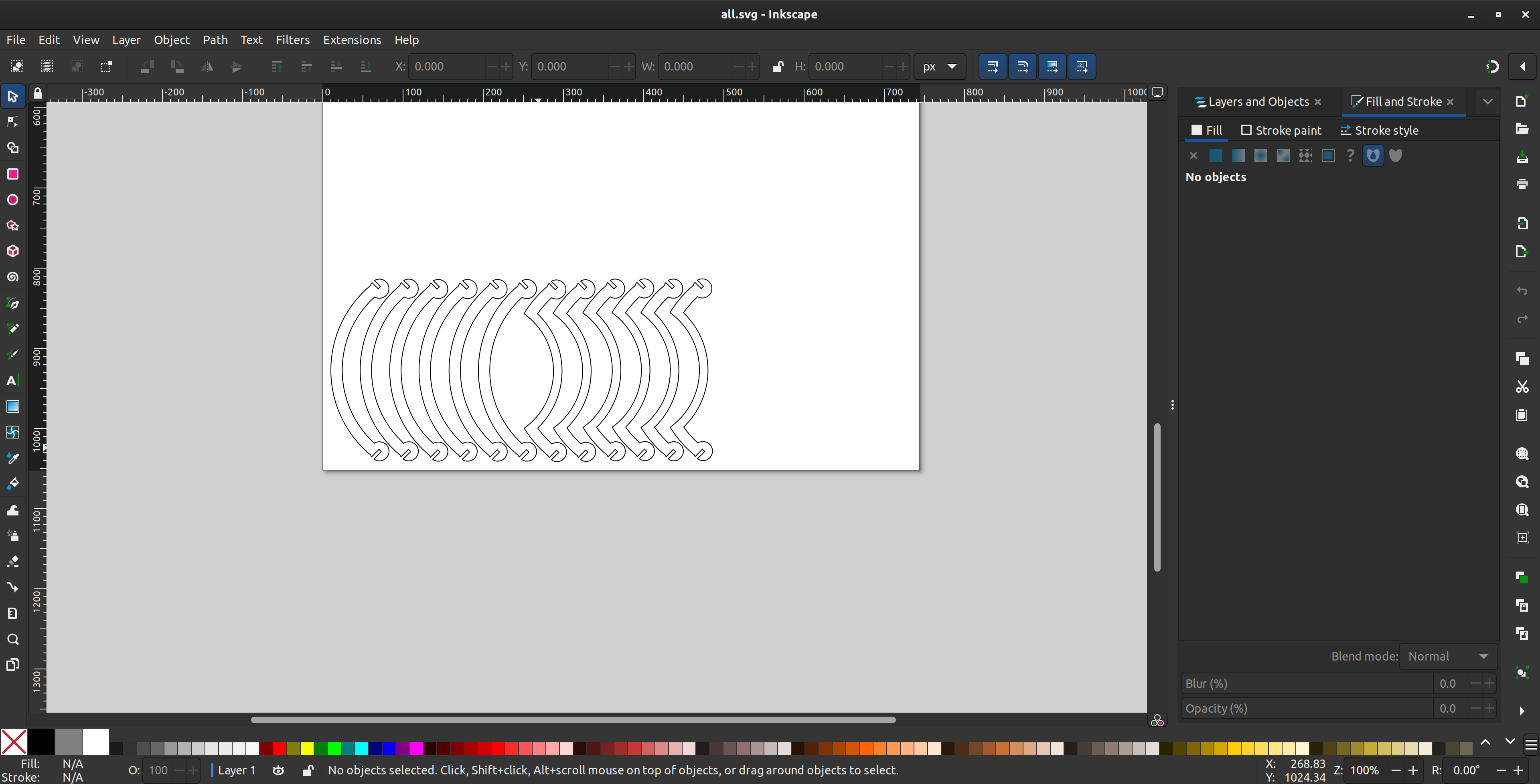
There are many versions on the internet, larger or smaller, I will design a medium one, with 2 types of pieces, 12 in total, with which you can put together several decorative pieces and of course, a ball, which is the objective. The design is in this this link
.jpg)
Once cut, it should look something like this, we are ready to put together whatever we want.
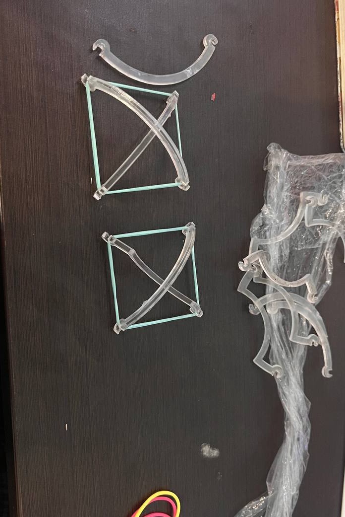
To put together anything with this design you need rubber bands, in this case we are going to go directly to put together the ball, for that it is necessary to first put together 6 squares, with 2 pieces, one of each.
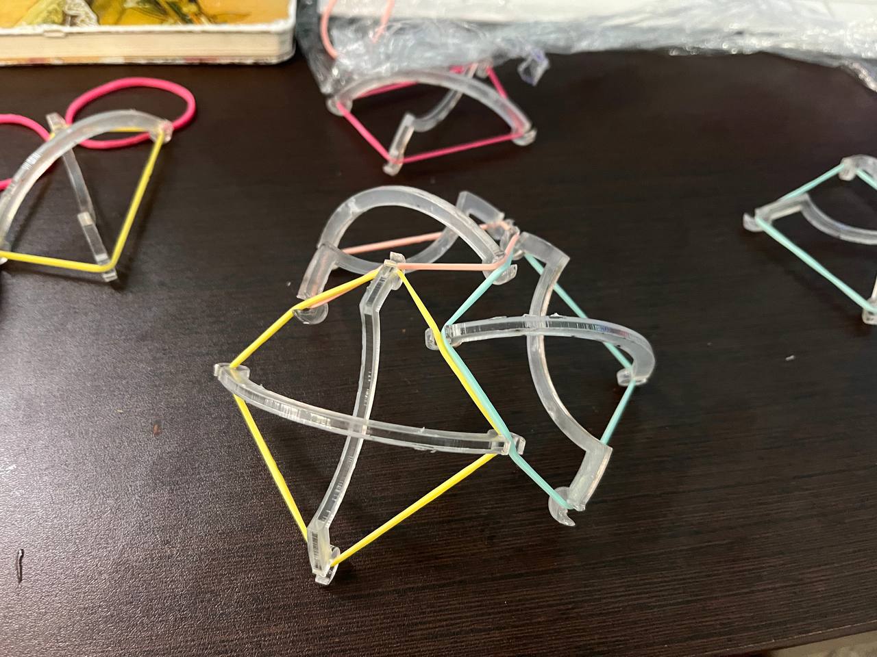
With the squares made, we must now join 3 of them to form this kind of "tent", once we have formed the two halves then we are ready to make the ball.
Result
Finally, the 2 halves, or the 6 squares, are put together to form this ball. It will bounce, but if you throw it too hard it will fall apart, hehe. The ideal is to leave it as decoration.