4. Embedded Programming
For week number 4, Embedded Programming we will program a board that can interact with input and output elements, with a demonstration example.
Group Assignment:
- Demonstrate and compare the toolchains and development workflows for available embedded architectures
- Document your work to the group work page and reflect on your individual page what you learned
Individual assignment:
- Browse through the datasheet for your microcontroller.
- Write a program for a microcontroller, and simulate its operation, to interact (with local input &/or output devices) and communicate (with remote wired or wireless connection)
Assignment Checklist.
| item | Activity | Status |
|---|---|---|
| task 1 | Linked to the group assignment page | DONE |
| task 2 | Browsed and documented some information from your microcontroller’s datasheet | DONE |
| task 3 | Programmed your simulated board to interact and communicate | DONE |
| task 4 | Described the programming process(es) you used. | DONE |
| task 5 | Included your source code | DONE |
| task 6 | Included a ‘hero shot’ | DONE |
Group Assignment.
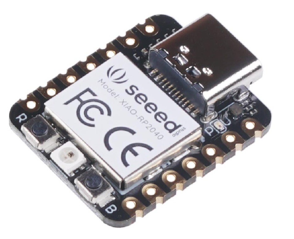
Seeed XIAO RP2040.
For this occasion within the FabAcademy international training program, the SEEED XIAO RP2040 development board will be used, so we will see the main features of the board; as well as the technical part of it, then let’s go…
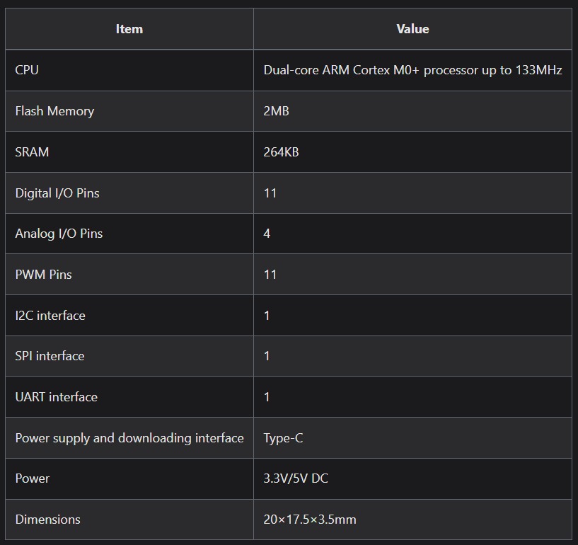
Technical Details SEEED XIOA RP2040
The documentation obtained for the development of this assignment was taken from freely accessible repositories:
MICROCONTROLLER INFORMATION LINK
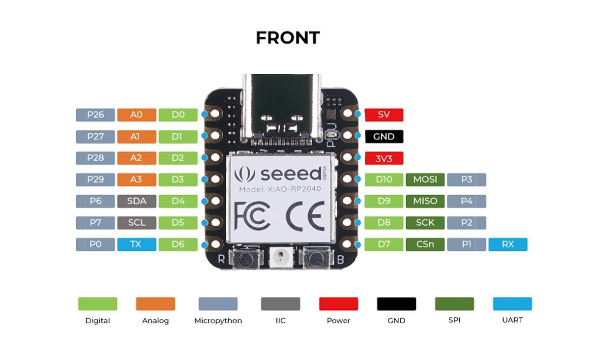
SEEED XIAO RP2040 connection pin outputs.
Main Technical Differences between SEEED XIAO RP2040 and SEEED XIAO ESP32 C3
- SEEED XIAO RP2040 Microcontroller: RP2040 (Raspberry Pi) CPU: Dual-core ARM Cortex-M0+ Clock speed: Up to 133 MHz Memory: 264 KB SRAM, no onboard flash memory Storage: 2 MB external flash memory Connectivity: No wireless connectivity Interface: USB 1.1, GPIO, SPI, I2C, UART Advantages: Higher processing power in applications that do not require wireless connectivity. Dual-core architecture for more efficient tasks. Disadvantages: No native wireless connectivity, which limits IoT applications. Requires external storage for large programs.
- SEEED XIAO ESP32 C3 Microcontroller: ESP32-C3 CPU: RISC-V Single-core Clock speed: Up to 160 MHz Memory: 400 KB SRAM, 4 MB flash memory Connectivity: Wi-Fi 802.11 b/g/n, Bluetooth 5.0 Interface: USB 2.0, GPIO, SPI, I2C, UART, ADC Advantages: Wi-Fi and Bluetooth integration, ideal for IoT projects. Higher clock speed and onboard memory. Support for a robust and widely used development ecosystem. Disadvantages: Higher power consumption compared to microcontrollers without wireless connectivity. Additional complexity in configuring connectivity. Advantages and Disadvantages in Programming SEEED XIAO RP2040:
Advantages: Support for multiple languages (C/C++, MicroPython), ideal for educational and learning projects. Disadvantages: No wireless connectivity, which limits network and IoT applications. SEEED XIAO ESP32 C3:
Advantages: Wide support for IoT, programming in C/C++, MicroPython and Arduino IDE. Integrated connectivity facilitates the development of connected applications. Disadvantages: Requires higher power consumption and more complex management of connectivity.
Individual assignment
Design for a programming board, where we can work with Arduino programming.
Example for programming.
For this case we can carry out several projects, but we are going to develop a project that controls a motor with a joystick.
#include <Servo.h>

Servo myServo;

const int servoPin = 0; // Pin de señal del servomotor
const int joystickXPin = A1; // Pin de señal X del joystick

int joystickXValue; // Valor de lectura del joystick en el eje X
int servoAngle; // Ángulo del servomotor

void setup() {
  myServo.attach(servoPin);
}

void loop() {
  joystickXValue = analogRead(joystickXPin);

  // Mapear el valor del joystick al rango de 0 a 180 (ángulo del servomotor)
  servoAngle = map(joystickXValue, 0, 1023, 0, 180);

  // Controlar el servomotor con el ángulo calculado
  myServo.write(servoAngle);

  delay(15); // Pequeña pausa para evitar vibraciones en el servomotor
}
Connection
We guide ourselves with the programming and also the connection pins part to complete the task
LEARNING, FINDING AND LESSONS
In the case of using development boards other than Arduino, but which can be worked within the programming environment, it is good to configure them correctly within the ARDUINO IDE.
