3. Computer Controlled Cutting
In this week number 3, we work with computer-controlled equipment, we will see the assignment of group and individual work.
INDIVIDUAL ASSIGNMENT. - Model (raster, vector, 2D, 3D, render, animate, simulate, …) a possible final project, compress your images and videos, and post a description with your design files on your class page
| item | Activity | Status |
|---|---|---|
| task 1 | Linked to the group assignment page. | DONE |
| task 2 | Explained how you created your parametric design. | DONE |
| task 3 | Documented how you made your press-fit construction kit. | DONE |
| task 4 | Documented how you made something with the vinyl cutter. | DONE |
| task 5 | Included your original design files. | DONE |
| task 6 | Included hero shots of your results. | DONE |
GROUP ASSIGNMENT:
For this section of computer aided cutting, we will identify our workspace, considerations in the correct use of PPE and parameters defined under our experience within the FABLAB of Universidad Continental - Cusco.
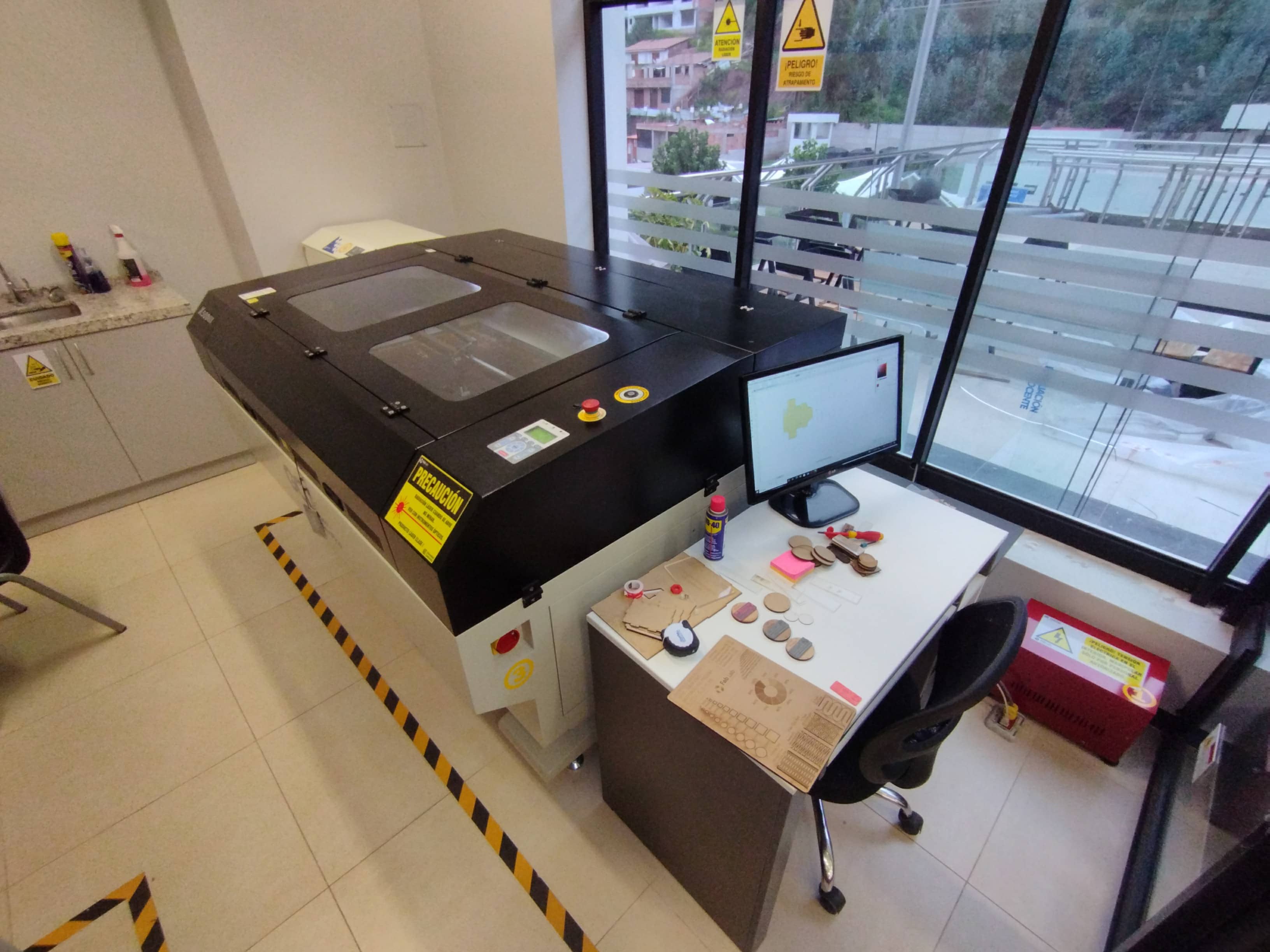
Inspection of our work area
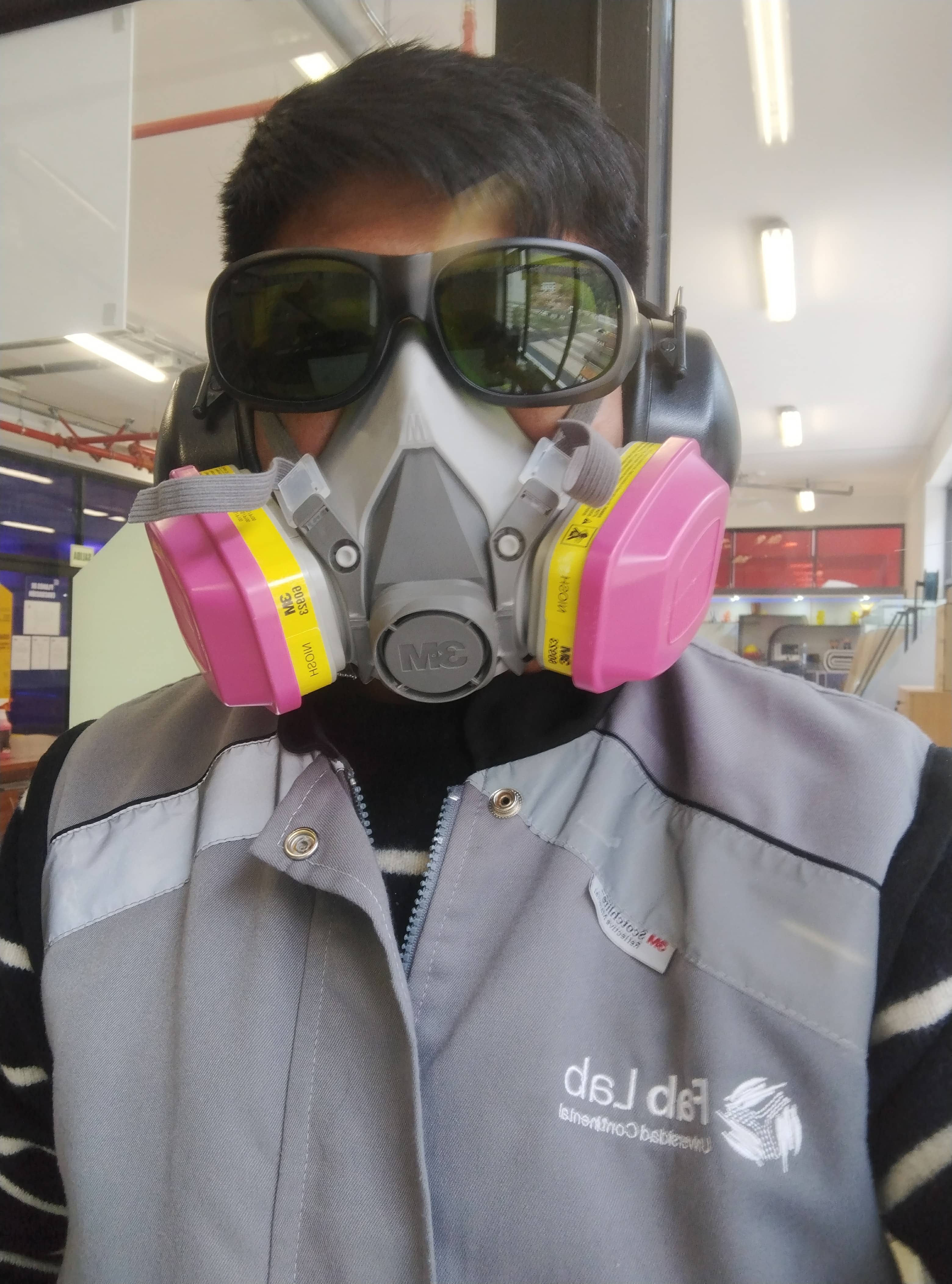
Safety
Before you start with everything do not forget to be with the corresponding PPE, for the case of laser cutting, which are: HALF FACE RESPIRATOR, EAR PLUGS, LASER PROTECTION GLASSES AND SAFETY GLOVES. It may seem uncomfortable, but it is better to be well protected.
Switch-on sequence
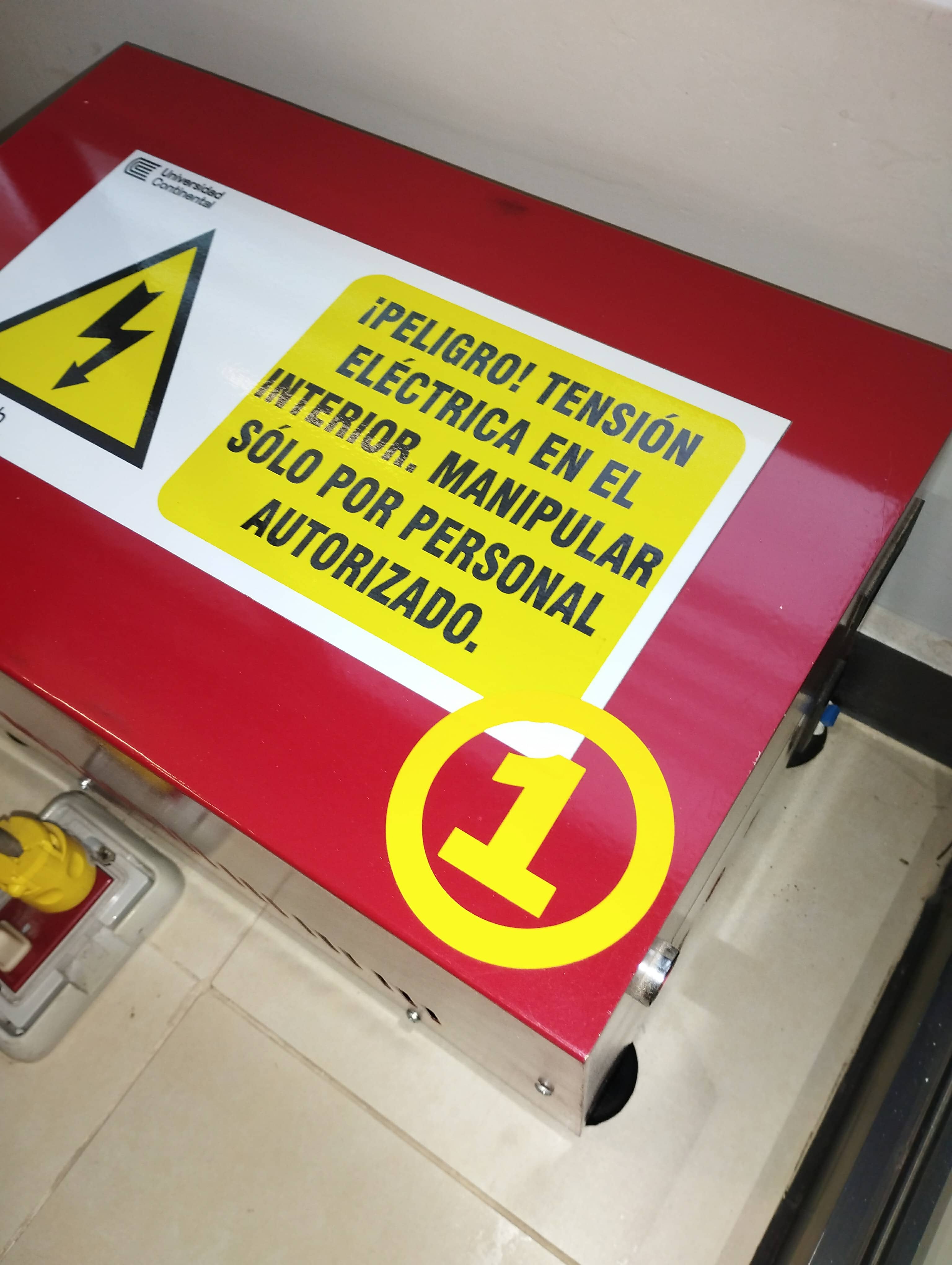
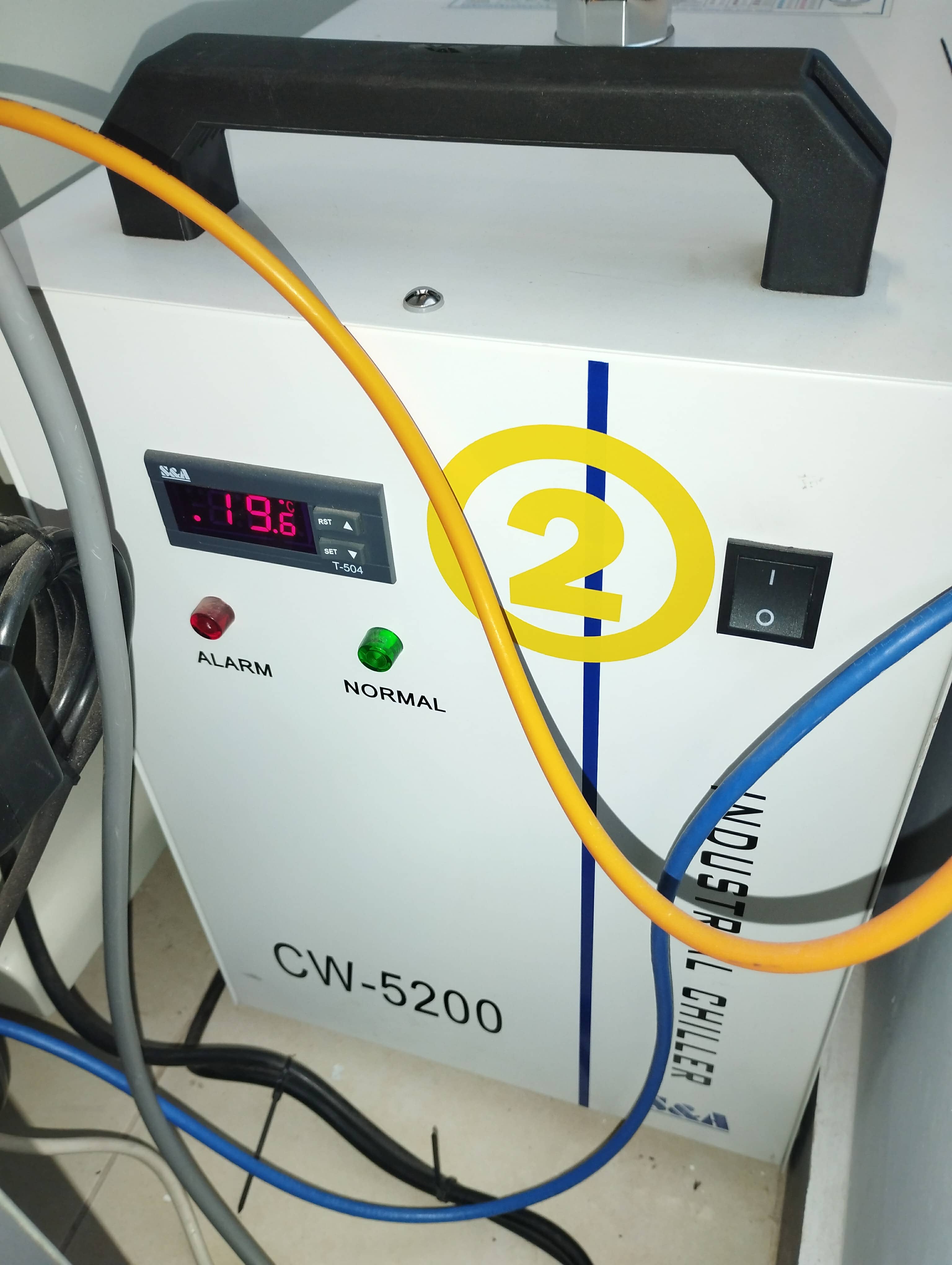
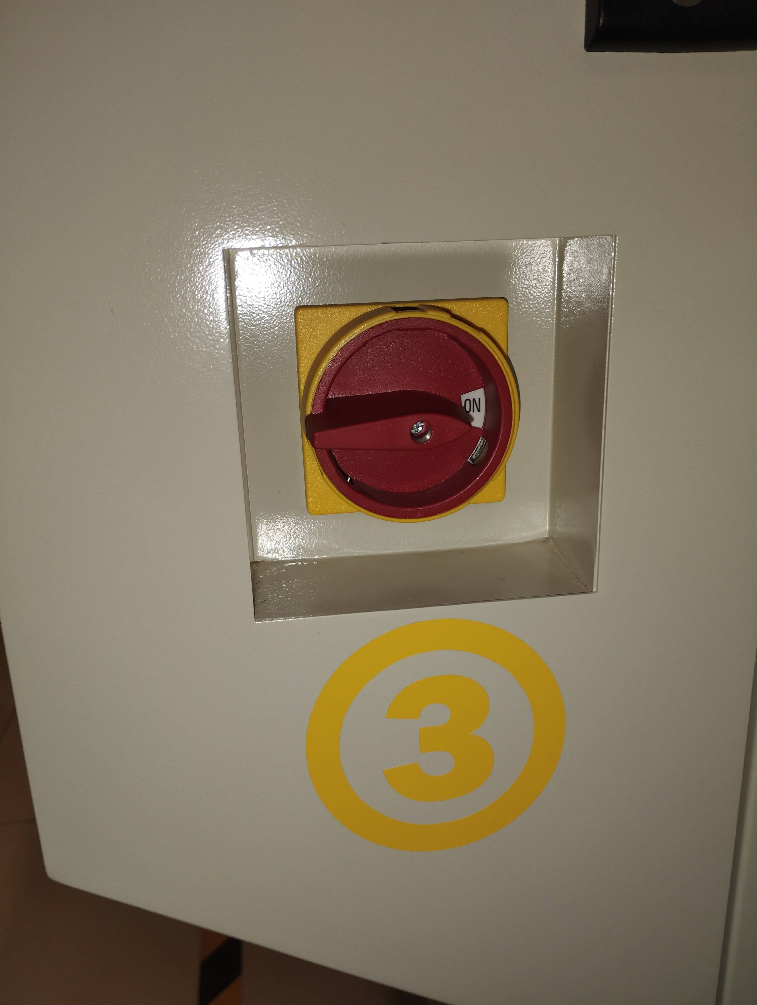
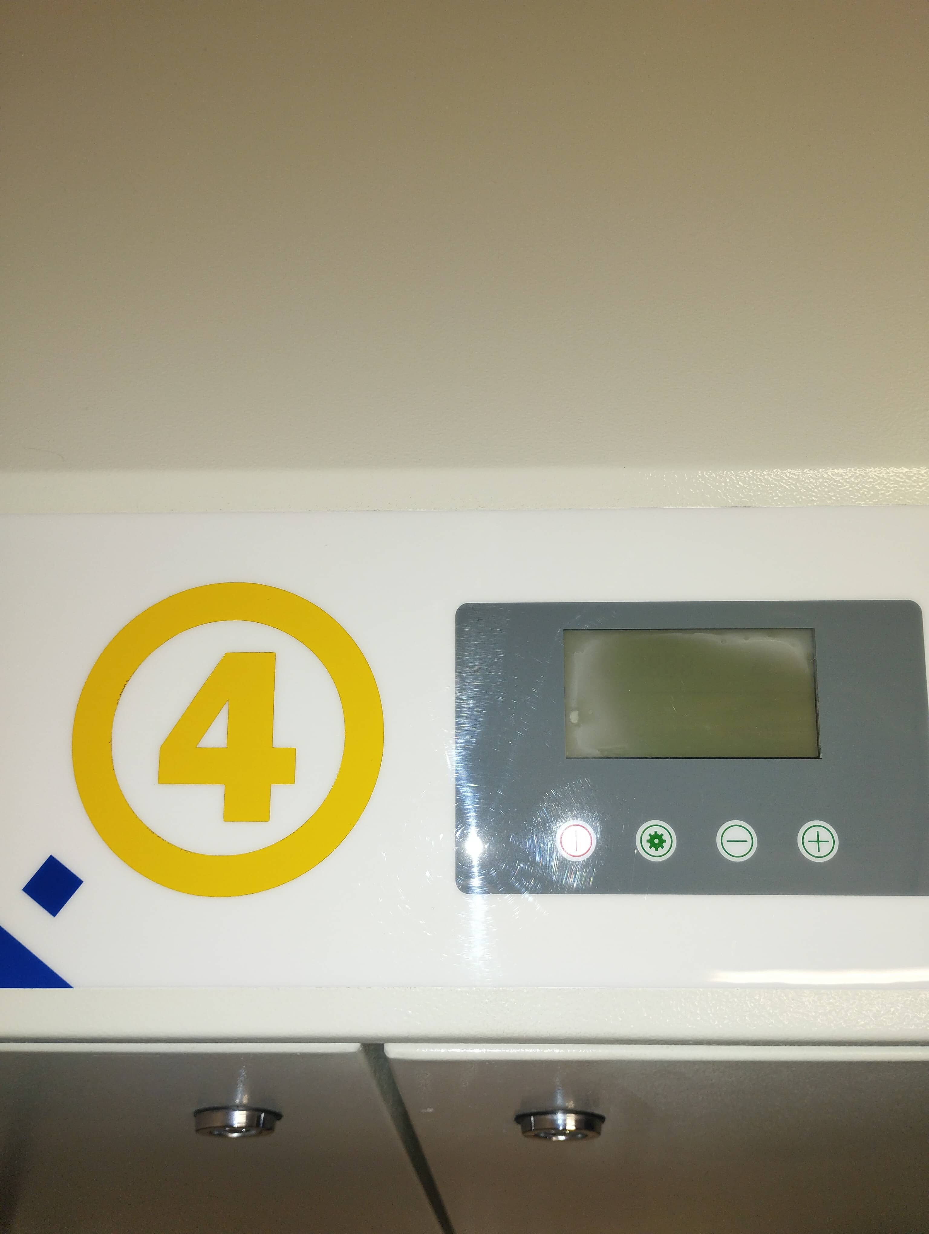
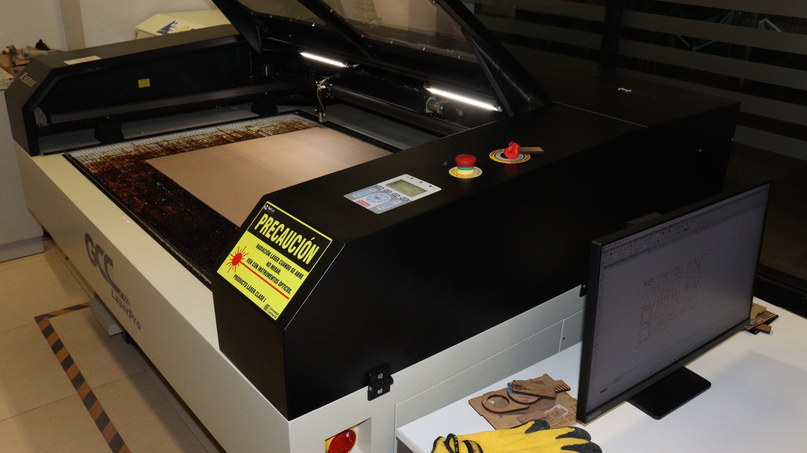
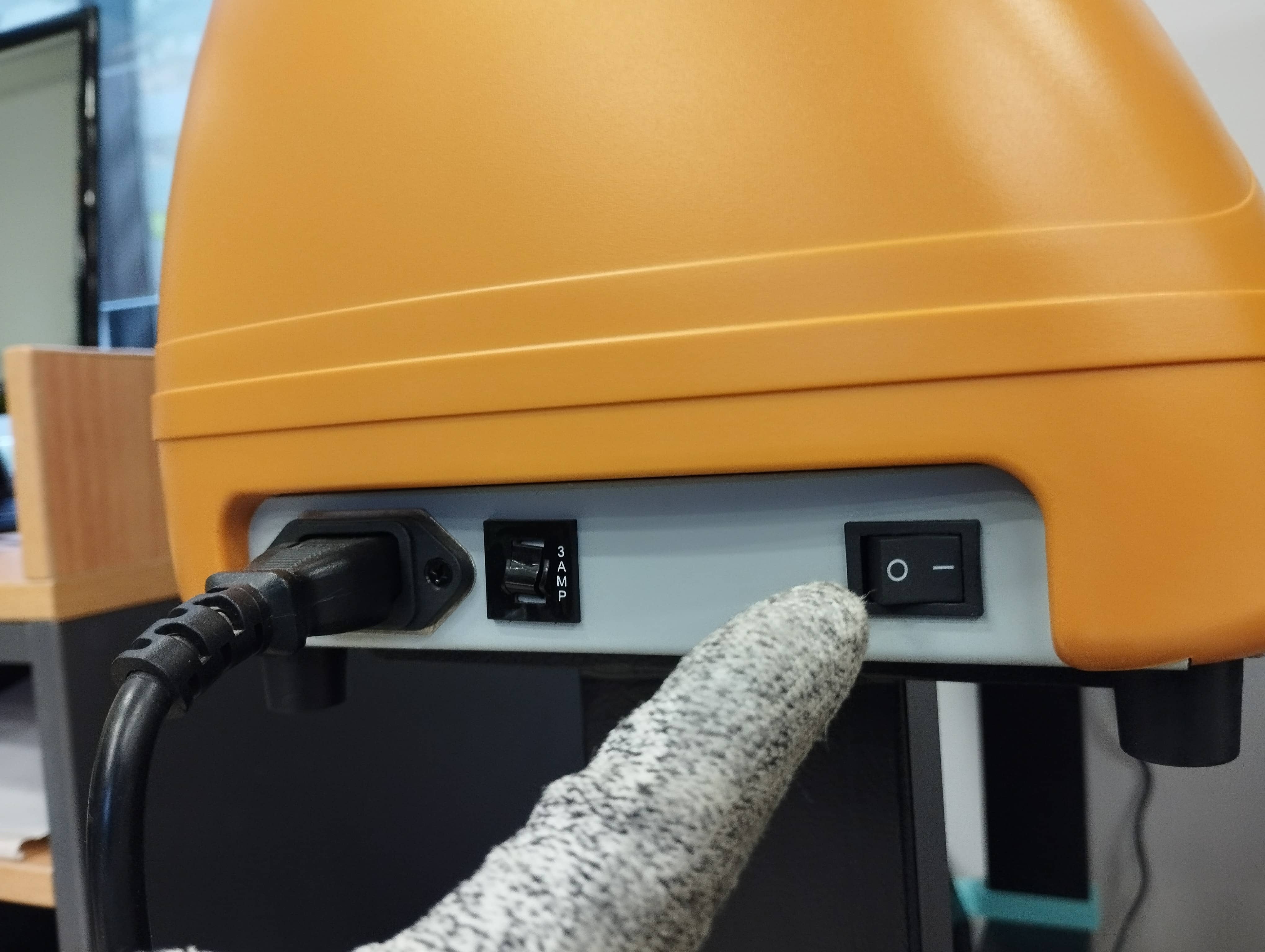
Here we are, in our work area, we have: 1. Voltage regulator. 2. Chiller liquid cooler. 3. Laser Cutting Equipment GCC X500III. 4. PURE AIR air purifying filter.
We proceed to turn on all the equipment according to the list: 1, 2, 3 and 4. In order not to have inconveniences or failures, to turn off all the equipment is in reverse, that is, 4, 3, 2 and 1, respectively.
1. VOLTAGE REGULATOR
2. CHILLER COOLING SYSTEM
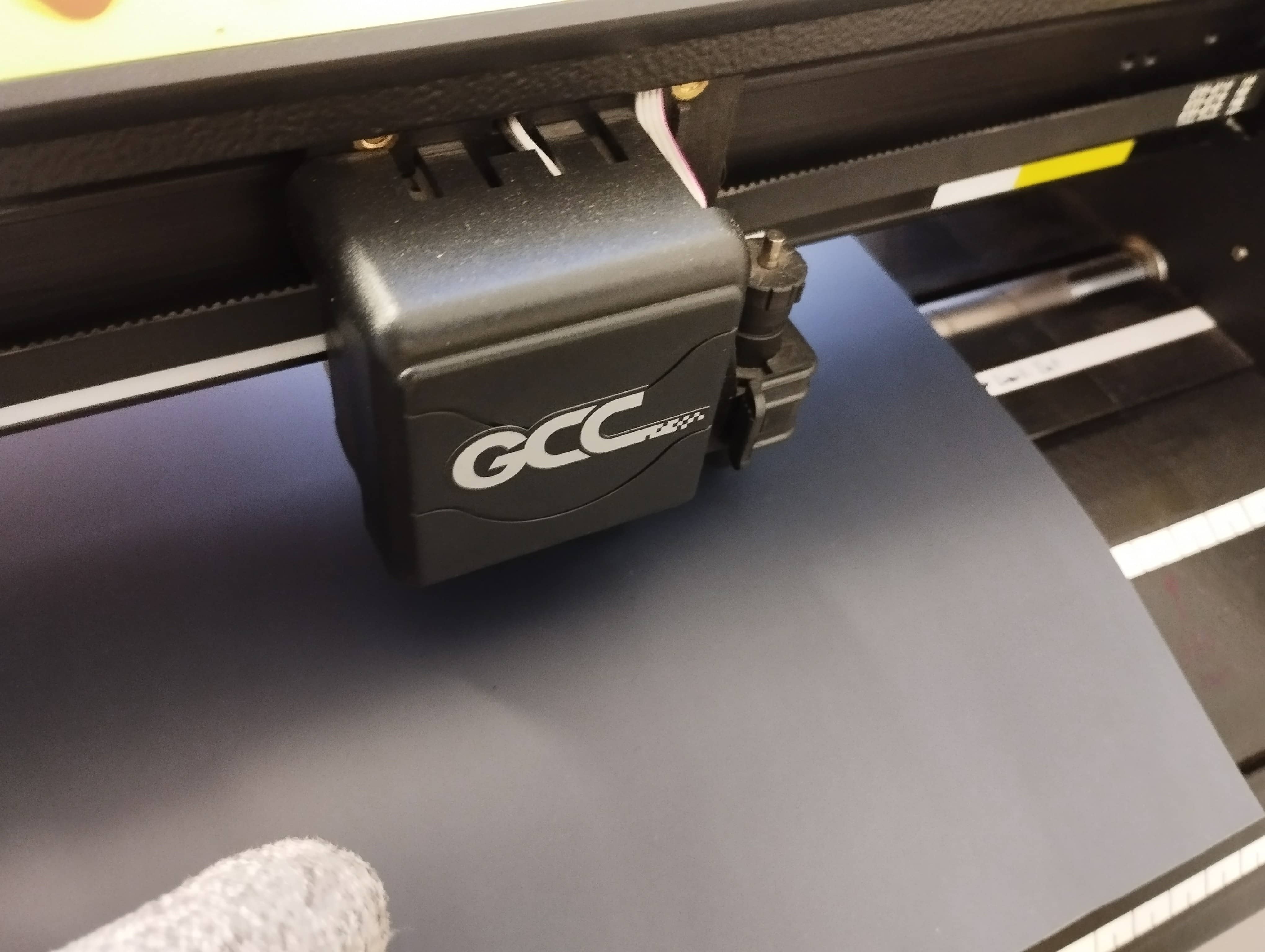
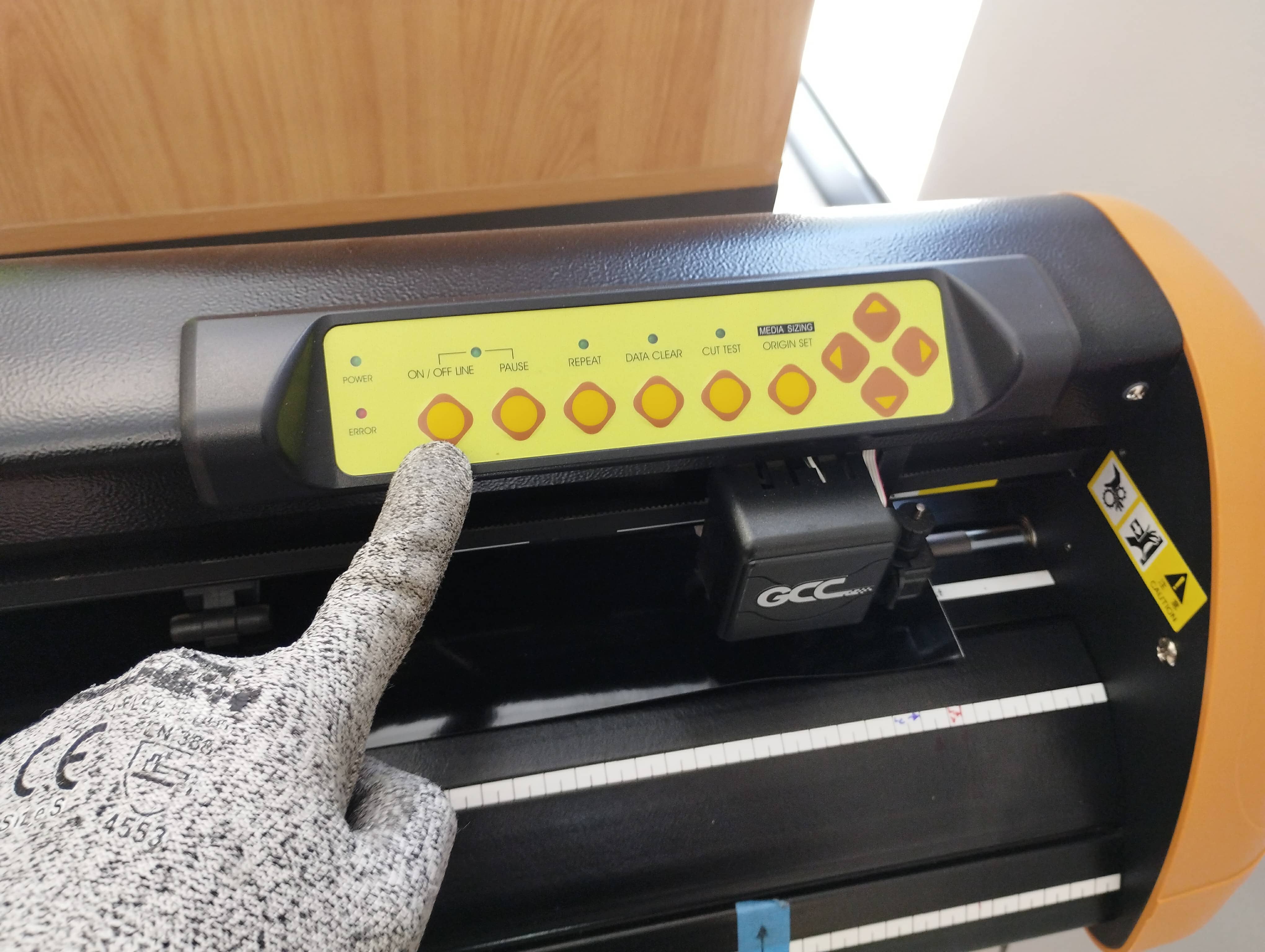
3. GCC LASER POWER SWITCH
4. PURE AIR SYSTEM.
DESIGN & CUT
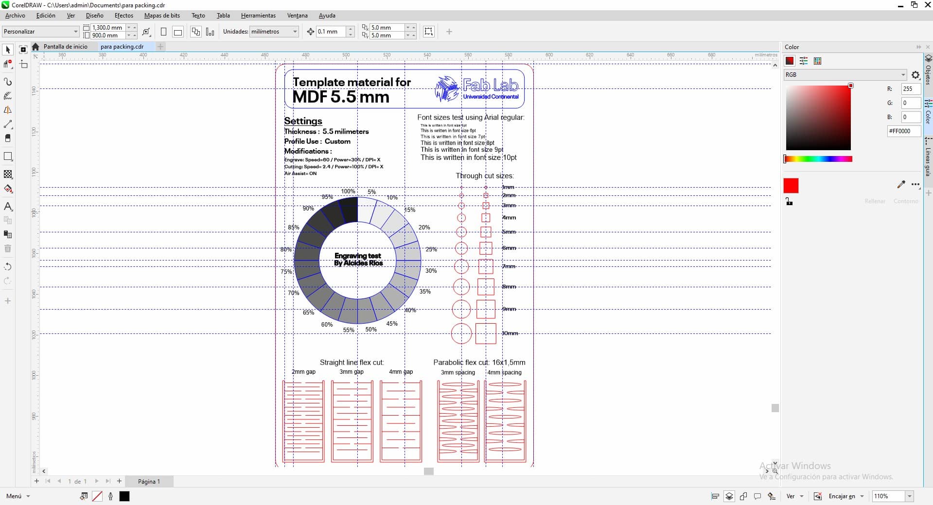
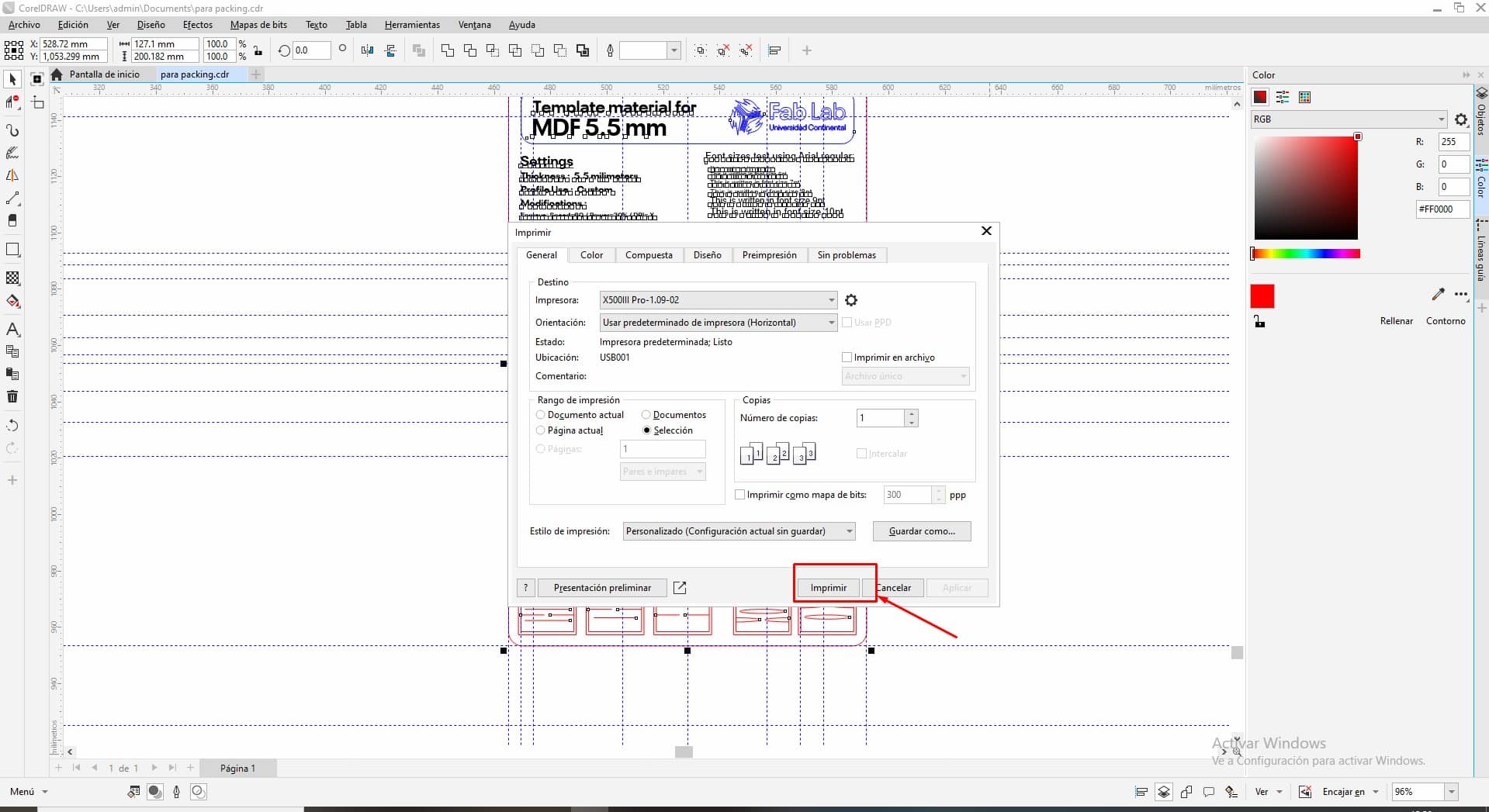
For the laser cutting and engraving process, we will choose to work with COREL DRAW software, since it allows us to work with vectors, ideal to indicate to the equipment which lines and powers to apply in this step.
 Once the design stage is finished, we will select the equipment installed in our laboratory, to define the most important parameters, such as: cutting speed, power and PPI.
These are very important to have good quality in cutting and engraving, as we also help to extend the life of our equipment.
Once the design stage is finished, we will select the equipment installed in our laboratory, to define the most important parameters, such as: cutting speed, power and PPI.
These are very important to have good quality in cutting and engraving, as we also help to extend the life of our equipment.

Once all the parameters have been defined, we simply hit print, that’s where the magic happens.
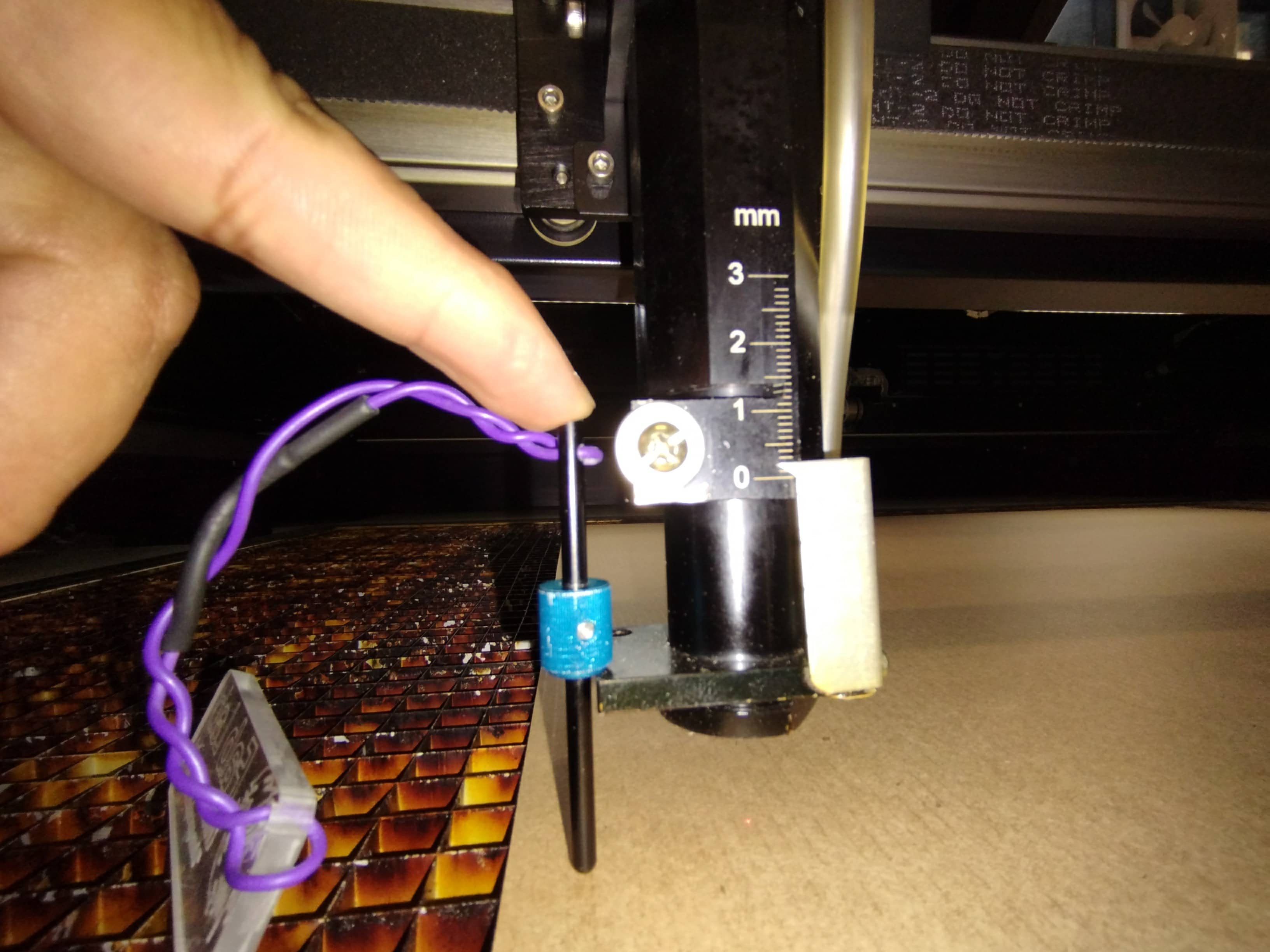
 Before we can cut we have to adjust the focal distance, so that the cuts and engravings are precise and we do not have problems when removing the cut material from the cutting table.
According to the sample provided in the photograph: Material thickness = focal length.
Before we can cut we have to adjust the focal distance, so that the cuts and engravings are precise and we do not have problems when removing the cut material from the cutting table.
According to the sample provided in the photograph: Material thickness = focal length.
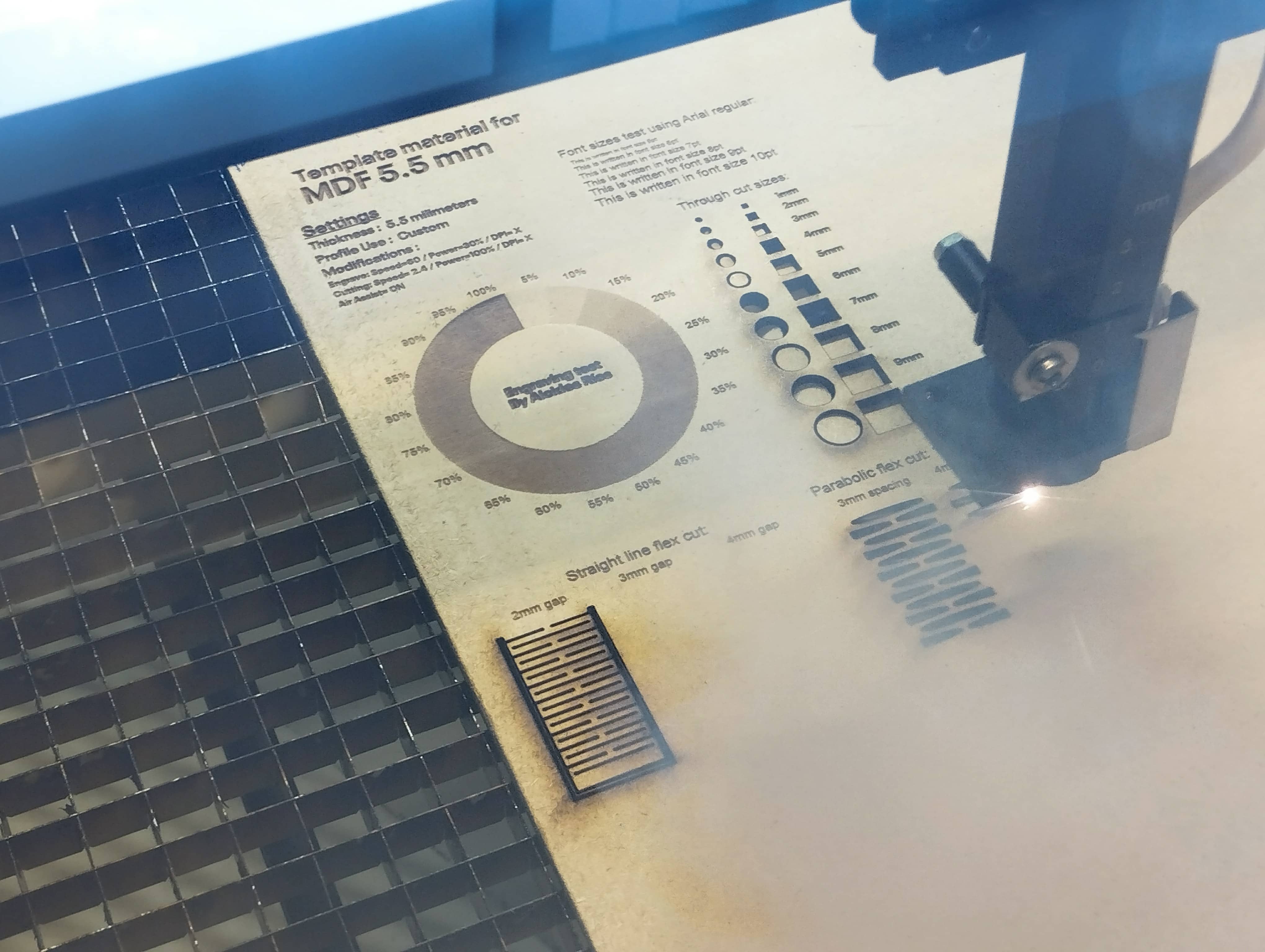
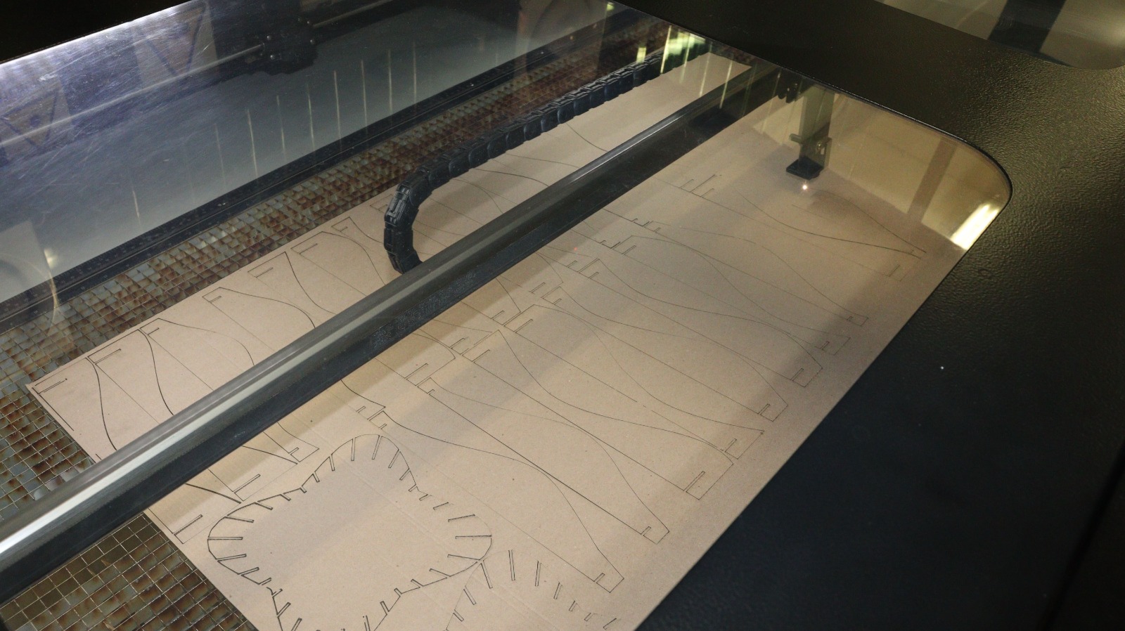
 Let’s observe the team working on the 5.5 mm thick MDF material, the parameters are also plotted on the material to be recorded.
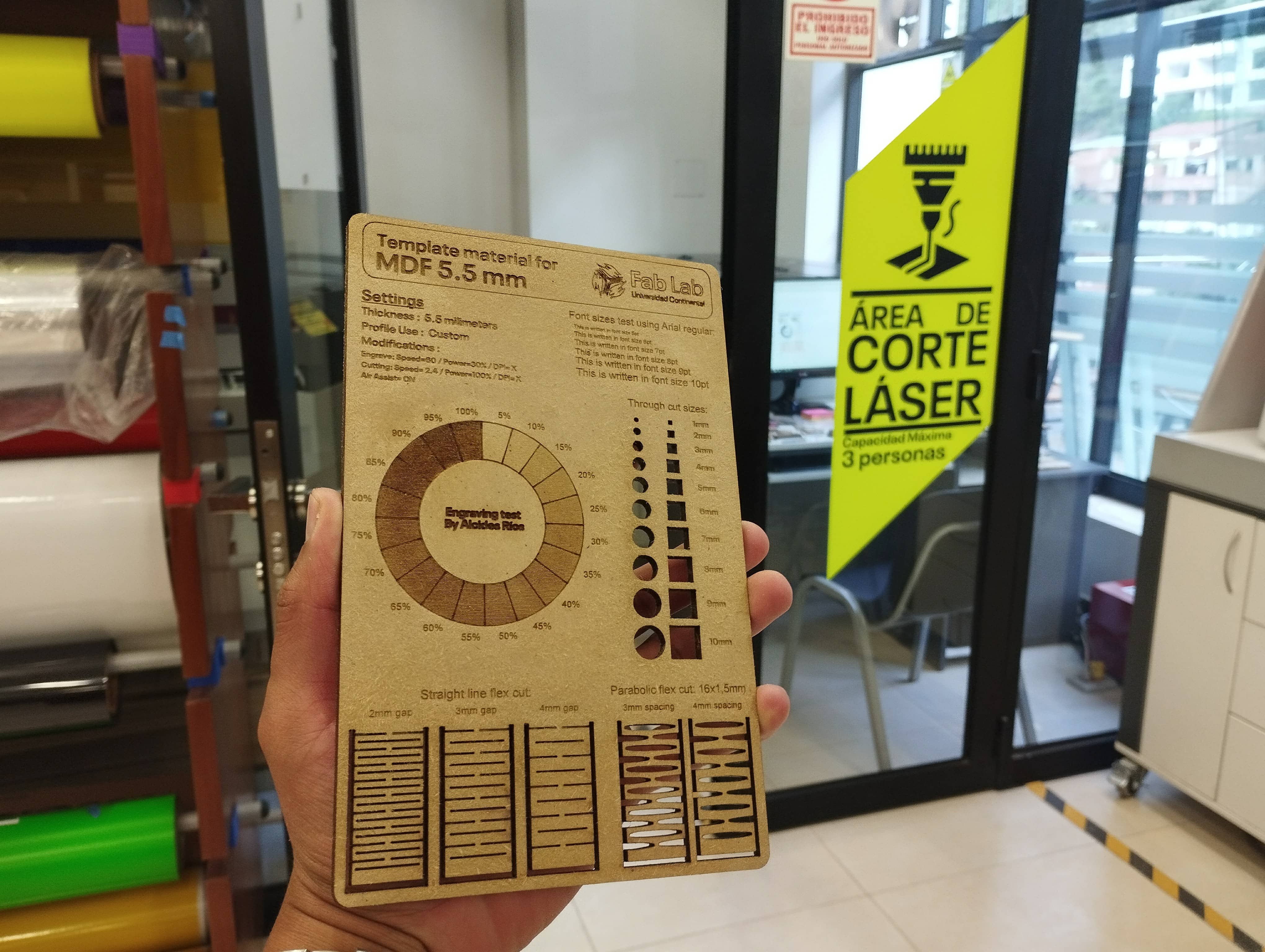
 After the cleaning generated by the cut, this is how it looks like.
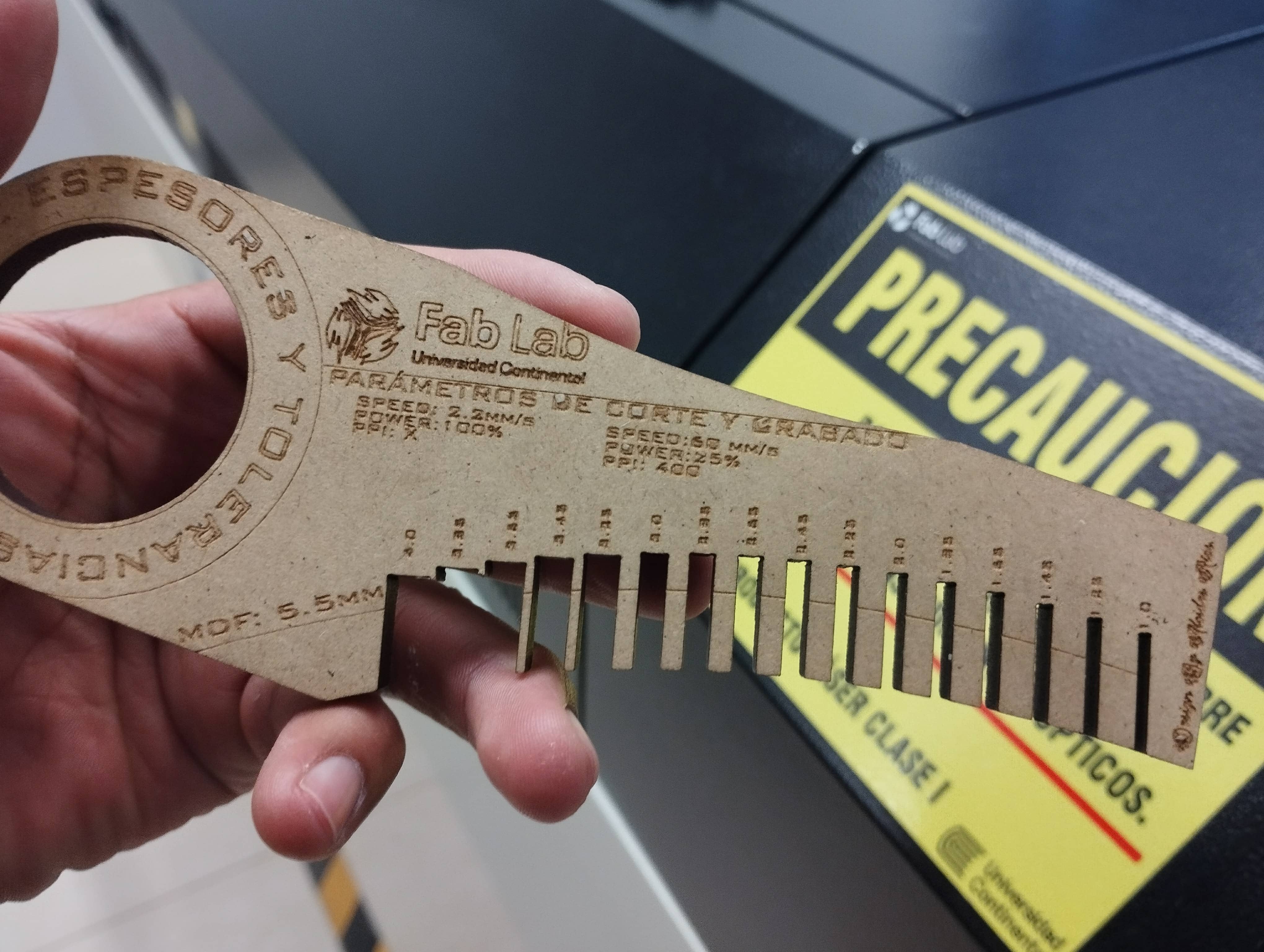
 Now with the cutting table as an example, we have a gauge that will help us in making measurements and tolerances for a better cut in socket parts.
 We design lace pieces for a sample pixel wall, these in union with others can generate interesting 3D images. so let’s see.
INDIVIDUAL ASSIGNMENT.
PARAMETRIC DESIGN AND CUTTING.
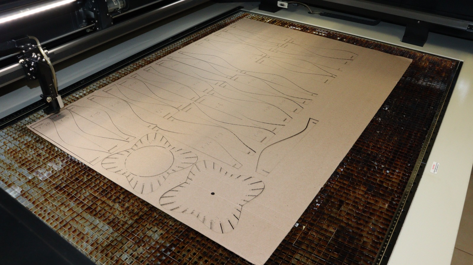
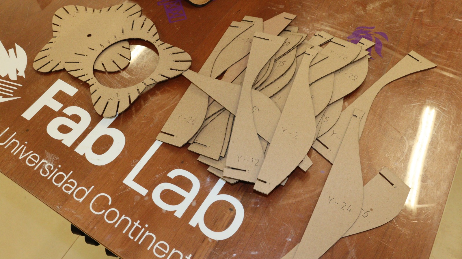
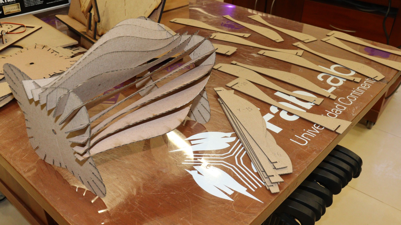
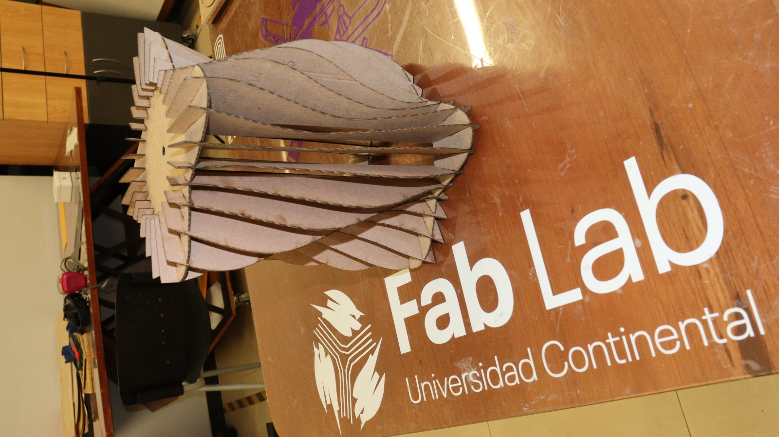
Let’s look at the following example, which has been made with 2mm cardboard model, an interesting-looking lamp whose shape changes with each face that is attached to the lower base and the upper cover.
- FIRST: We define the shape and order of the design so it can be generated.
- SECOND: We use AutoCAD to generate the inner and outer circles, along with some irregular extensions and slotted sections for inserting the other pieces.
- THIRD: The inserted sections are generated from rectangular strips. After that, the protruding wave-shaped section is proportionally varied, gradually grouping them together.
This is how we generate the pieces in the parametric design.
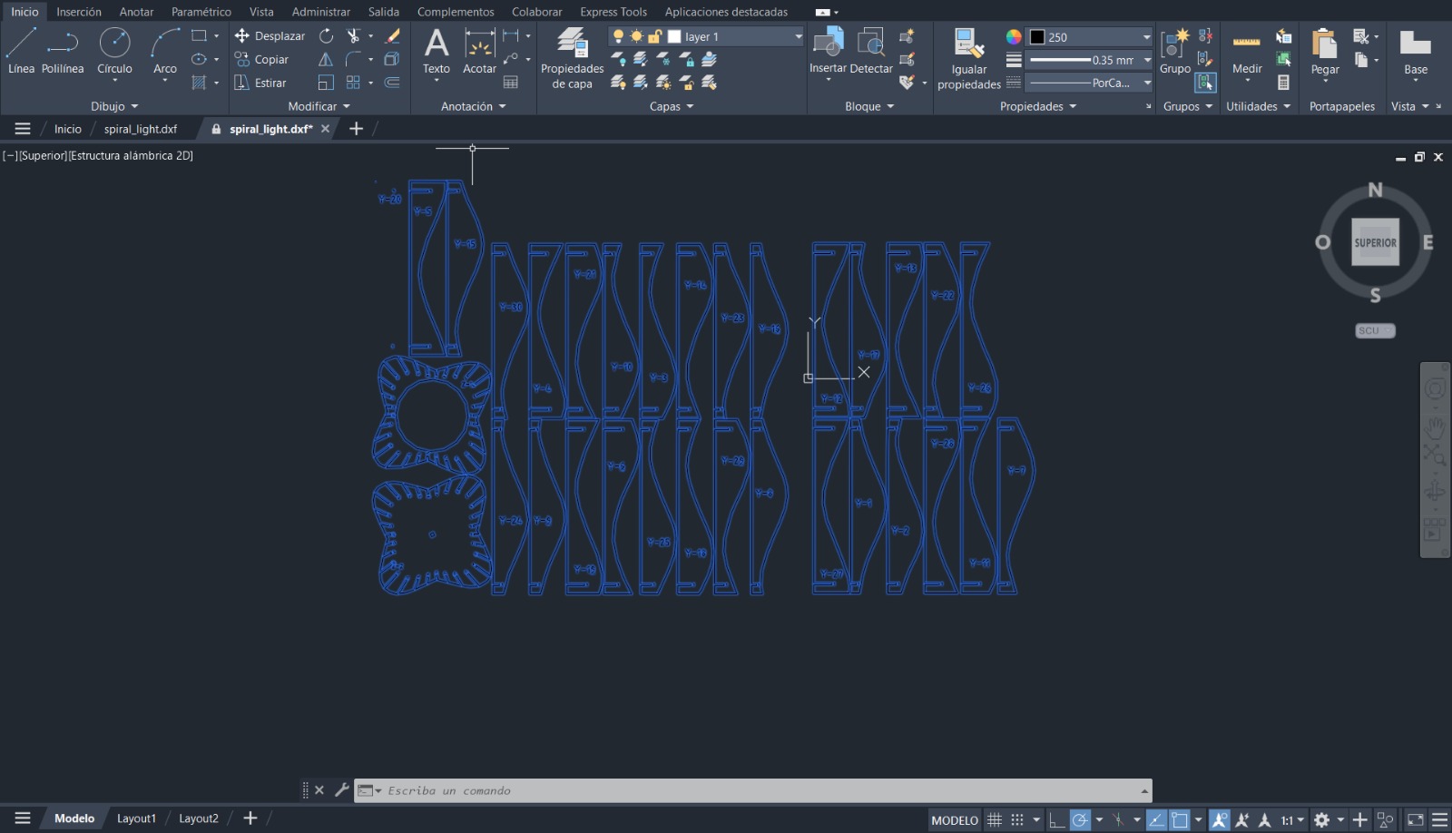
Once finished, the file is exported in DXF format, with the corresponding lines for the cutting and engraving process. - Red Line: Cutting. - Blue Line: Engraving
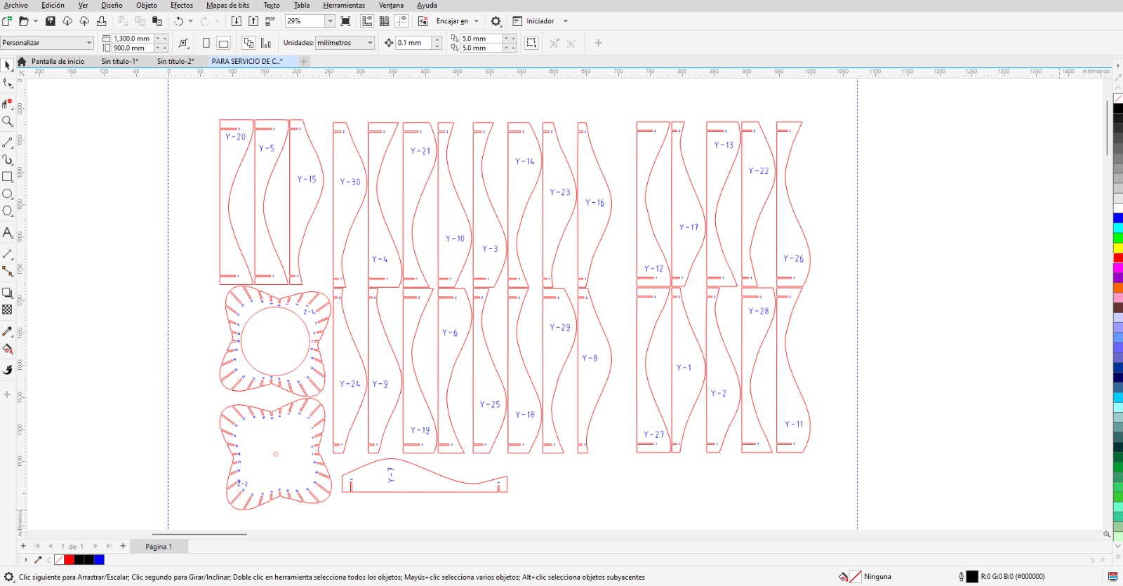
We place the material on the laser cutting machine’s work table, align it, set the focal length, and finally specify the parameters for the cut, including engraving on 2mm microcorrugated cardboard.
- CUTTING: power (100), speed (3.6), PPI (X)
- ENGRAVING: power (8), speed (25), PPI (Default)
-
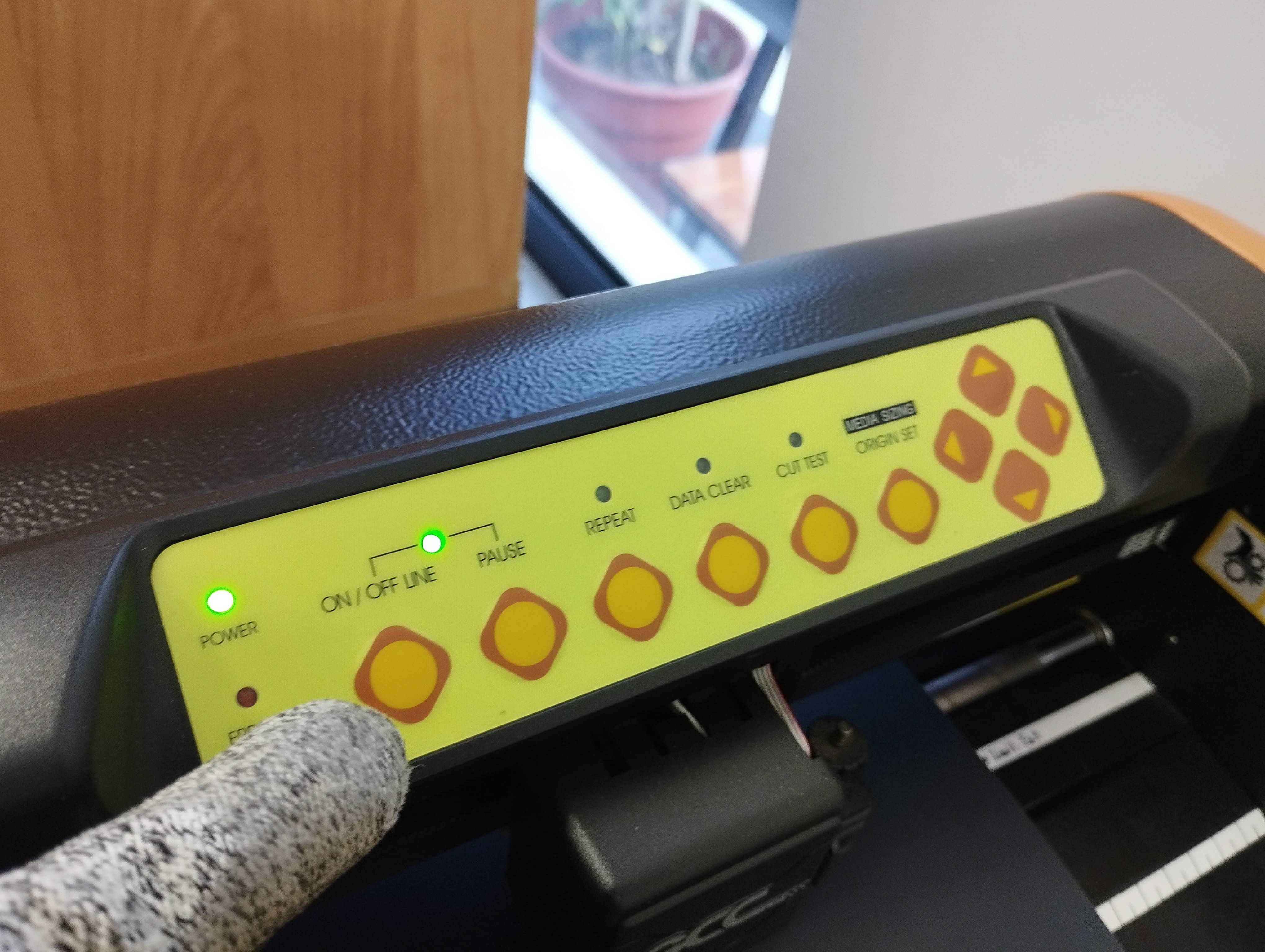
VINYL CUTTING
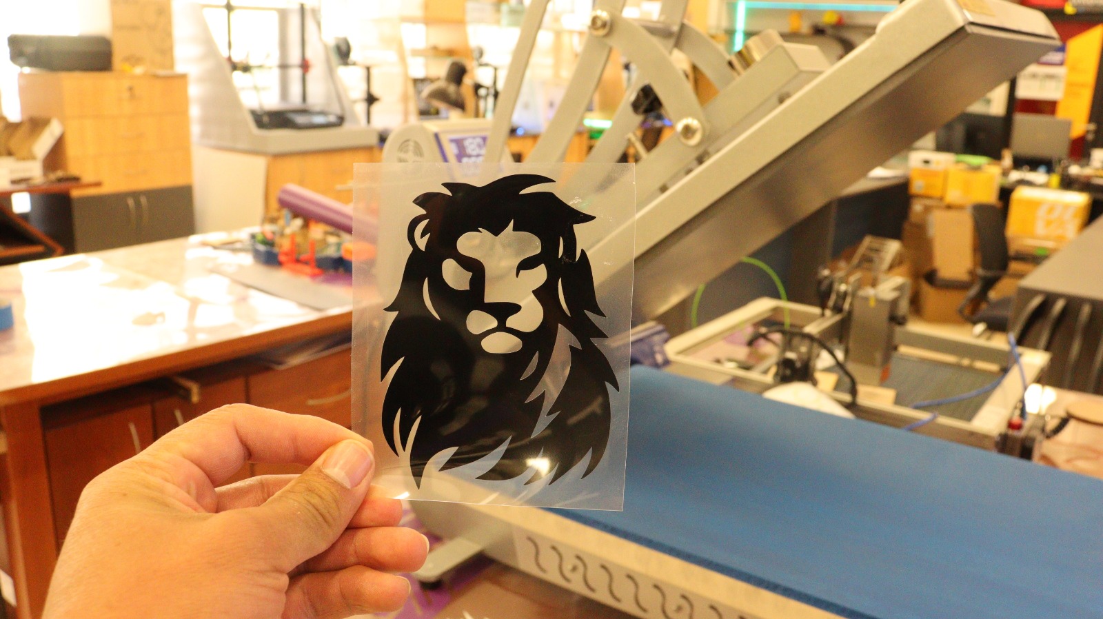
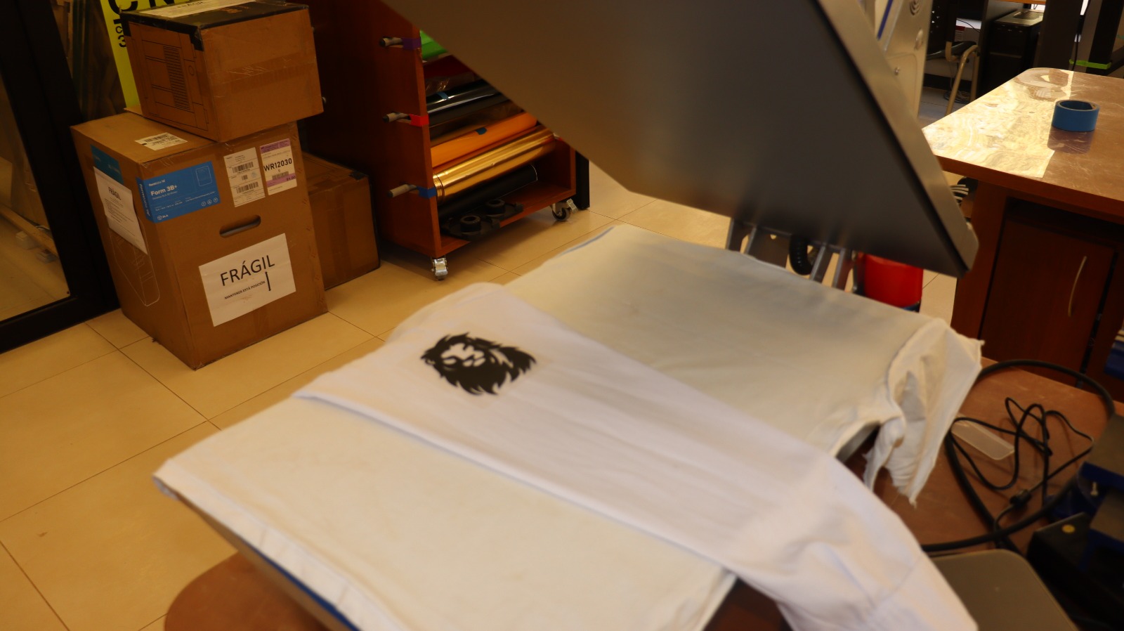
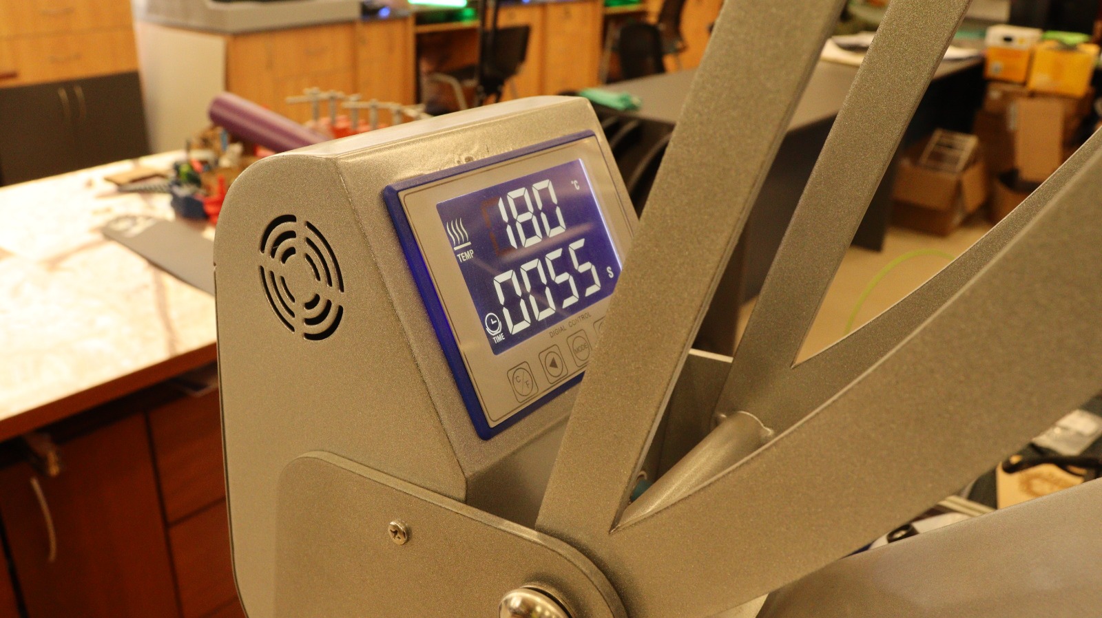
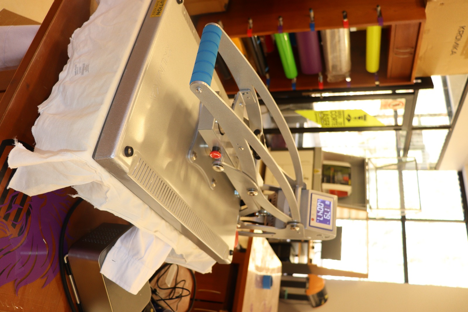
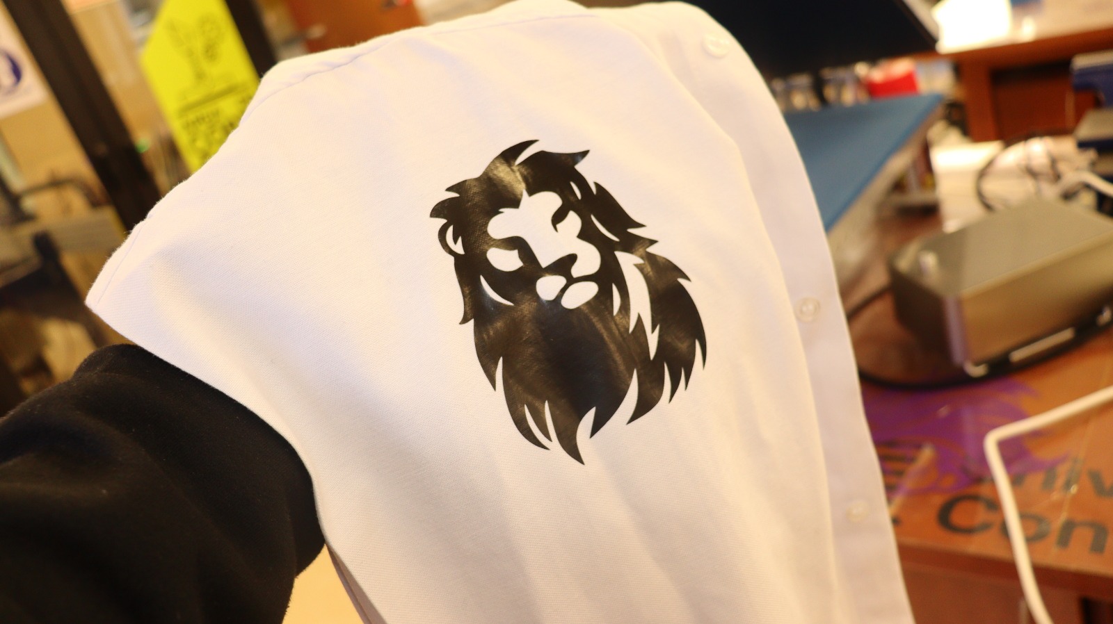
Well, now this process is similar to laser cutting, because we work with vectors, and we change some parameters like: FORCE and SPEED. On the vinyl, which is a material that adheres to almost any surface, except rough or textrurized surfaces. Then, we will make a printing process with textile vinyl, let’s go!
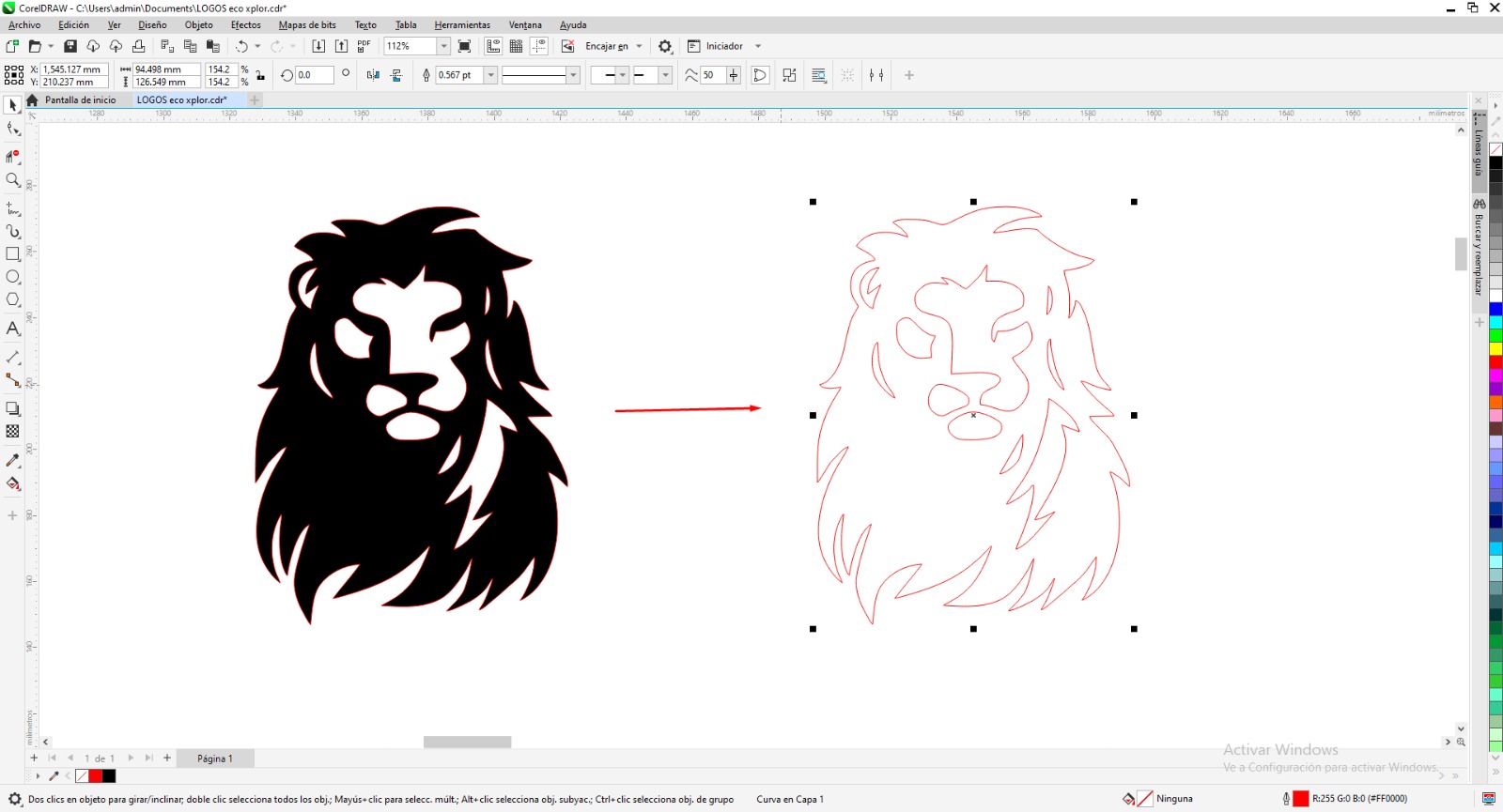
We load our textile vinyl to the cutting area, calibrate ends and fix.
Files for download ( DXF files)
- Cutting test for MDF Click Here
- Parametric cutting design Click Here
- Vinyl cutting design Click Here
LEARNING, FINDING AND LESSONS
The lesson learned in the laser cutting process is: take into account the thickness of the line left by the laser cutting trace, so we can take into account that an approximate tolerance of 0.25 mm must be given.