On the Wednesday of thirteenth week, Mr. Neil sir conducted our thirteenth global session. He took the random generator in first 90 minutes. He gave us overall explaination about week-13 which includes Networking and Communications.
In this assignment, I have made documentation on- Group Assignment
1. Send a message between two projects. Individual Assignment
1. Design, build, and connect wired or wireless node(s) with network or bus addresses and local input &/or output device(s).
Basics of Networking and Communication:-
Networking and communication in electrical engineering and electronics form the backbone of modern information exchange. These systems interconnect devices, such as computers, printers, and sensors, enabling them to share resources and data efficiently. Networks can be categorized into local area networks (LANs), which connect devices within a confined area like a building, and wide area networks (WANs), which cover larger geographical areas. Mobile networks facilitate connectivity for devices on the move.
Communication within networks occurs through various media, including cables (like Ethernet) and wireless technologies (such as Wi-Fi and cellular networks). Key hardware components, such as routers, switches, and access points, manage data traffic and ensure devices can communicate smoothly.
Central to networking are communication protocols, which are standardized sets of rules that dictate how data is transmitted and received. Protocols like TCP/IP (Transmission Control Protocol/Internet Protocol) ensure reliable and organized data exchange across the Internet and other networks. These protocols cover aspects like data formatting, error handling, and synchronization, allowing different devices and systems to communicate seamlessly.
Overall, networking and communication systems are essential for enabling the interconnected world we live in, supporting everything from personal computing to large-scale industrial operations and global Internet connectivity.
There are two types of communication methods - Serial and Parallel
DAY-02
Group Assignment Click here to read more about group assignment. Individual Assignment
In the individual assignment, I documented on Design, build, and connect wired or wireless node(s) with network or bus addresses and local input &/or output device(s).
So, here I learned two way communication between two XIAO-ESP32-C3 microcontroller using serial communication.
Here, I refer the YouTube Video for two communication between the microcontrollers. There are two nodes, one XIAO-ESP32-C3 microcontroller is Transmitter to transmit the signals and another is Receiver to receive the signal.
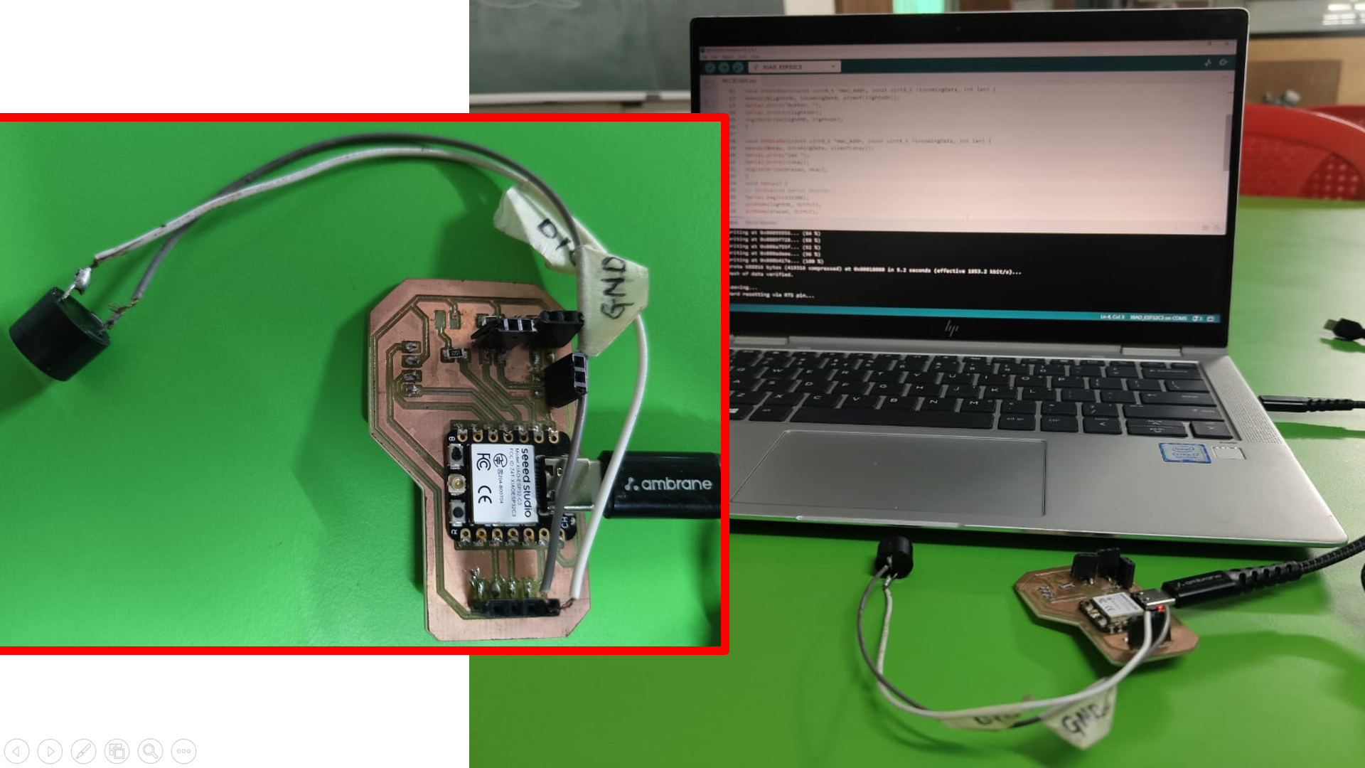
Firstly, I took two XIAO-ESP32-C3 PCB boards that I already made in previous assignments. I have made Transmitter PCB in the Input Devices Assignment and Receiver PCB in the Electronic Design Assignment.
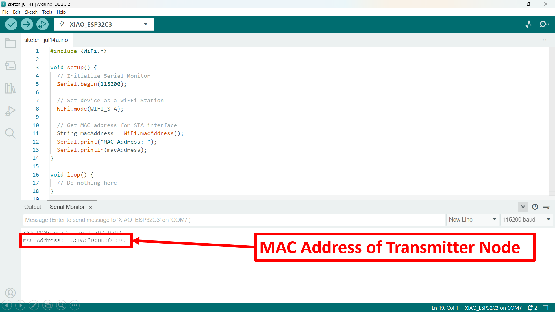
Here, I decided to interface MQ135 Gas sensor at Transmitter node and received its data to the Receiver node to Turn On the Buzzer. Before integrationn of this system, I have to know the MAC addresses of both the microcontrollers which is necessary for the serial communication between them. To find the MAC Address of both the microcontroller, here I used the following code -
        #include < WiFi.h>


            void setup() {

              // Initialize Serial Monitor

              Serial.begin(115200);


              // Set device as a Wi-Fi Station

              WiFi.mode(WIFI_STA);


              // Get MAC address for STA interface

              String macAddress = WiFi.macAddress();

              Serial.print("MAC Address: ");

              Serial.println(macAddress);

            }


            void loop() {

              // Do nothing here

            }
Upload this code in both the microconntrollers using Arduino IDE.
Firslt, I have uploaded this code in the Transmitter PCB and here I got the MAC Address of the transmitter node.
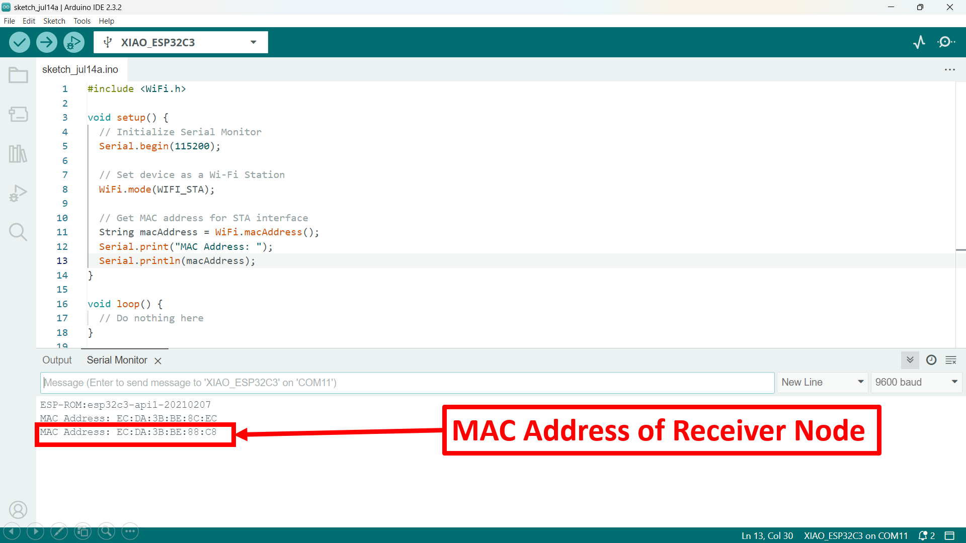
Again, I got the MAC Address of Receiver node simply by uploading the code in the Receiever PCB.
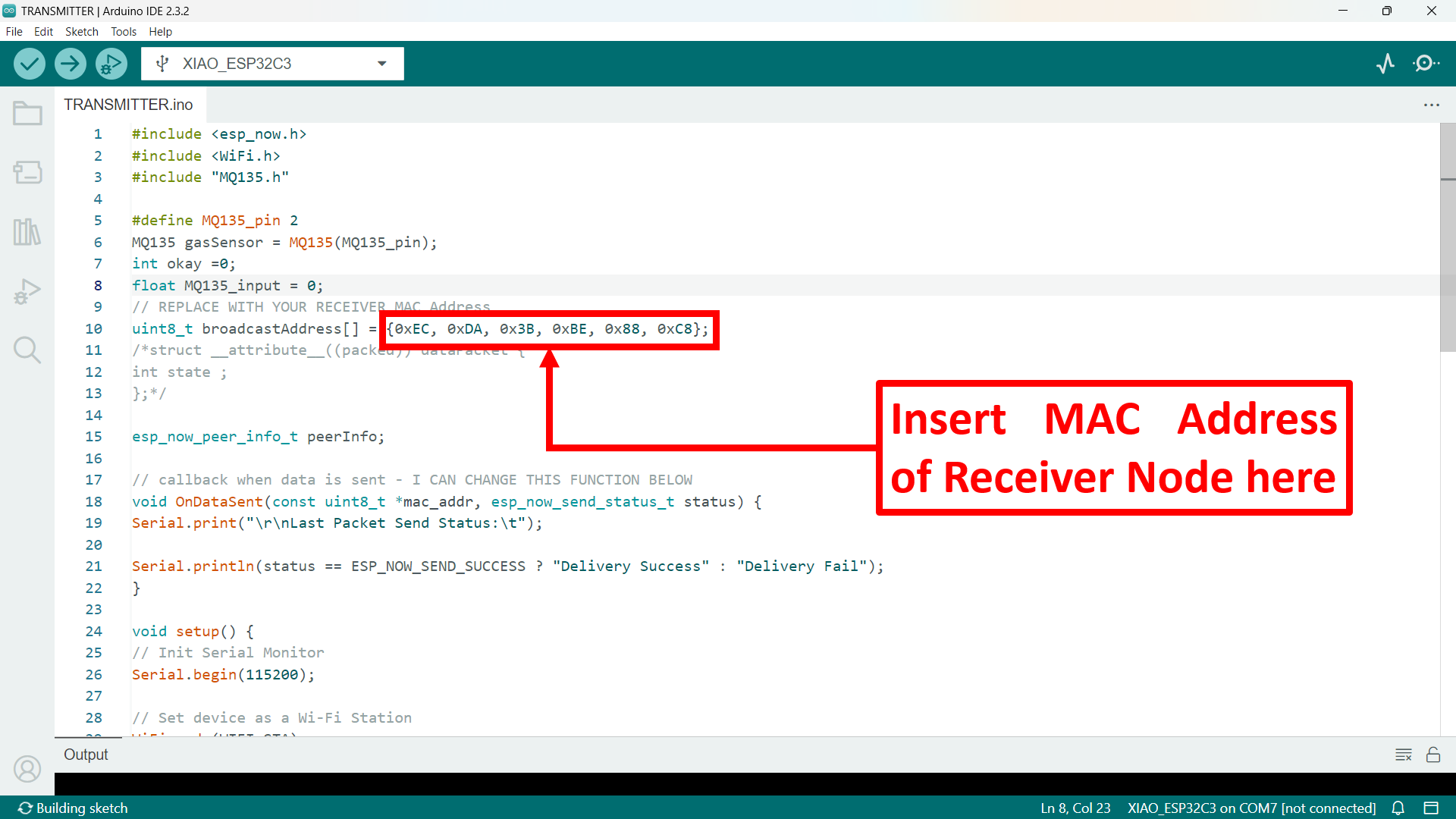
Now, I got both the MAC Addresses. So, here I inserted the MAC address of Receiver node in the code of Receiever node which help to communnicate both the microcontrollers wirelessly.
Following are the steps to communicate both the microcontrollers wirelessly -
Transmitter Node -
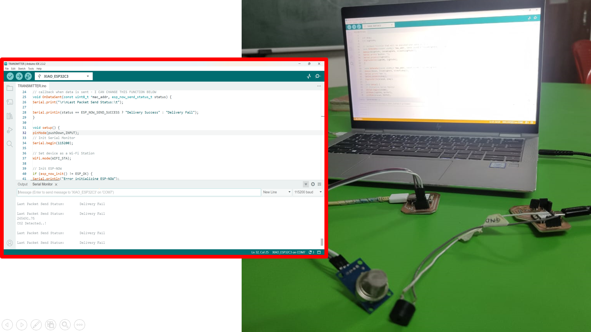
Firstly, I uploaded the code of Transmitter node in the one XIAO-ESP32-C3 using Arduino IDE. Code -
#include < esp_now.h>
#include < WiFi.h>
#include "MQ135.h"
#define MQ135_pin 2
MQ135 gasSensor = MQ135(MQ135_pin);
int okay =0;
float MQ135_input = 0;
// REPLACE WITH YOUR RECEIVER MAC Address
uint8_t broadcastAddress[] = {0xEC, 0xDA, 0x3B, 0xBE, 0x91, 0x38};
/*struct __attribute__((packed)) dataPacket {
int state ;
};*/
esp_now_peer_info_t peerInfo;
// callback when data is sent - I CAN CHANGE THIS FUNCTION BELOW
void OnDataSent(const uint8_t *mac_addr, esp_now_send_status_t status) {
Serial.print("\r\nLast Packet Send Status:\t");
Code Explaination -
This code uses ESP-NOW for wireless communication between ESP32 microcontrollers, and it reads CO2 levels using the MQ135 gas sensor connected to the D2 pin of the XIAO ESP32-C3 microcontroller.
In the setup, I start by initializing the serial monitor for debugging and set the device to Wi-Fi station mode. I then initialize ESP-NOW, and if there's an error, it prints a message. The pin for the MQ135 gas sensor is configured as an input.
Once ESP-NOW is successfully initialized, I register a callback function `OnDataSent` to get the status of transmitted packets. I then register a peer with the specified MAC address for communication. If adding the peer fails, it prints an error message.
In the loop, I read the CO2 levels from the MQ135 gas sensor. If the CO2 level exceeds 20 PPM, I toggle the `okay` variable and print a message indicating CO2 detection. Finally, I send the value of `okay` to the registered peer using ESP-NOW. The code essentially monitors CO2 levels and wirelessly sends an alert when high levels are detected.
Receiver Node -
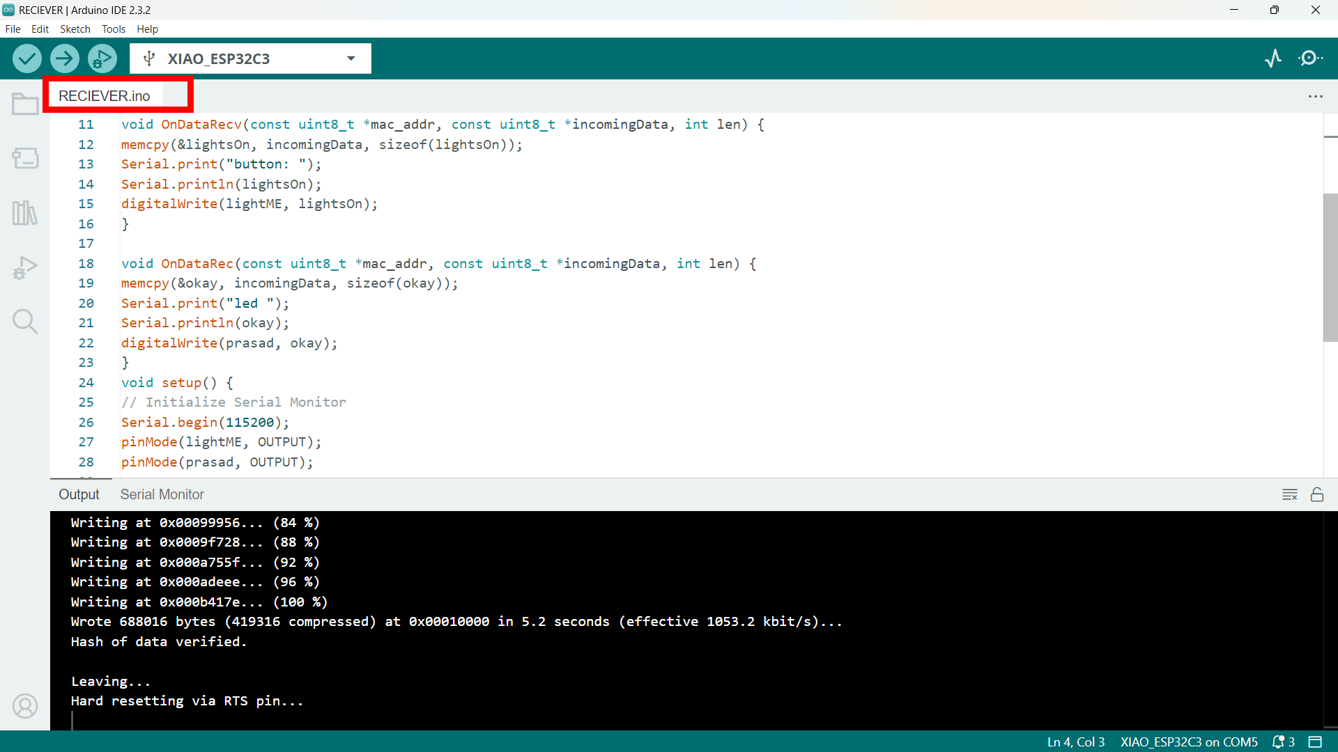
Now, I uploaded the code of Receiver node in the another XIAO-ESP32-C3 using Arduino IDE. Code -
#include < esp_now.h>
#include < WiFi.h>
// Register for receive callback function
esp_now_register_recv_cb(OnDataRecv);
}
void loop() {
// Nothing to do here
}
Code Explaination -
This code configures an ESP32 microcontroller to receive data using the ESP-NOW protocol and control a buzzer based on the received data. The buzzer is connected to pin D10 of the microcontroller, defined as `prasad` in the code.
In the setup function, I initialize the serial monitor for debugging and set the pin mode for the buzzer as an output. The device is set to operate in Wi-Fi station mode, which is necessary for ESP-NOW communication. The ESP-NOW protocol is initialized, and if there is an error during this process, an error message is printed to the serial monitor.
I register a callback function `OnDataRecv` that is triggered whenever data is received. This function copies the incoming data into the `okay` variable and prints its value to the serial monitor. Depending on the received data, the function also sets the state of the buzzer by writing the value of `okay` to the `prasad` pin (D10).
In the loop function, there is no additional logic since all the required actions are handled within the callback function when data is received. This setup ensures that the ESP32 microcontroller can react to incoming data by activating or deactivating the buzzer.
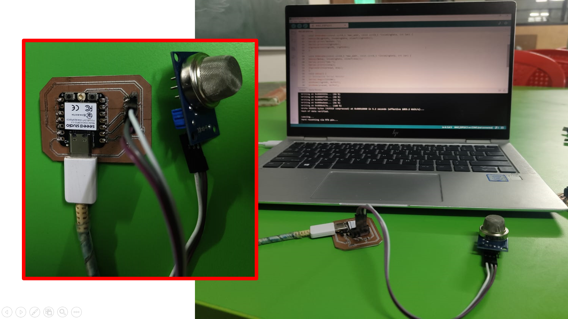
In this setup, the system comprises two ESP32 microcontrollers communicating via ESP-NOW to monitor CO2 levels and control a buzzer. The first ESP32, which acts as the transmitter, reads CO2 levels from an MQ135 gas sensor connected to its D2 pin. When the sensor detects a CO2 concentration greater than 20 PPM, it toggles a variable `okay` and sends this value to the second ESP32 microcontroller.
The second ESP32, which serves as the receiver, has a buzzer connected to its D10 pin. It listens for incoming data from the transmitter. When it receives the `okay` value indicating high CO2 levels, it activates the buzzer by setting the D10 pin high. This setup ensures that when hazardous CO2 levels are detected by the sensor, the buzzer sounds an alert, thereby providing a warning in real-time.
Here is the final output.
In this setup, the ESP-NOW protocol is employed to facilitate efficient and reliable wireless communication between two ESP32 microcontrollers. ESP-NOW is a low-power, peer-to-peer wireless communication protocol developed by Espressif, the makers of the ESP32. It enables multiple devices to communicate with each other without the need for a traditional Wi-Fi network or router, making it ideal for applications requiring direct, low-latency communication.
ESP-NOW operates by allowing devices to send and receive small amounts of data (up to 250 bytes) directly to each other's MAC addresses. This protocol is particularly useful in scenarios where low-latency communication is critical, such as in the described setup where one ESP32 microcontroller monitors CO2 levels using an MQ135 gas sensor and needs to promptly alert another microcontroller to activate a buzzer when dangerous levels are detected. The simplicity and efficiency of ESP-NOW make it a robust solution for IoT applications, ensuring reliable performance even in environments with limited network infrastructure.