1. Group assignment:
send a message between two projects.
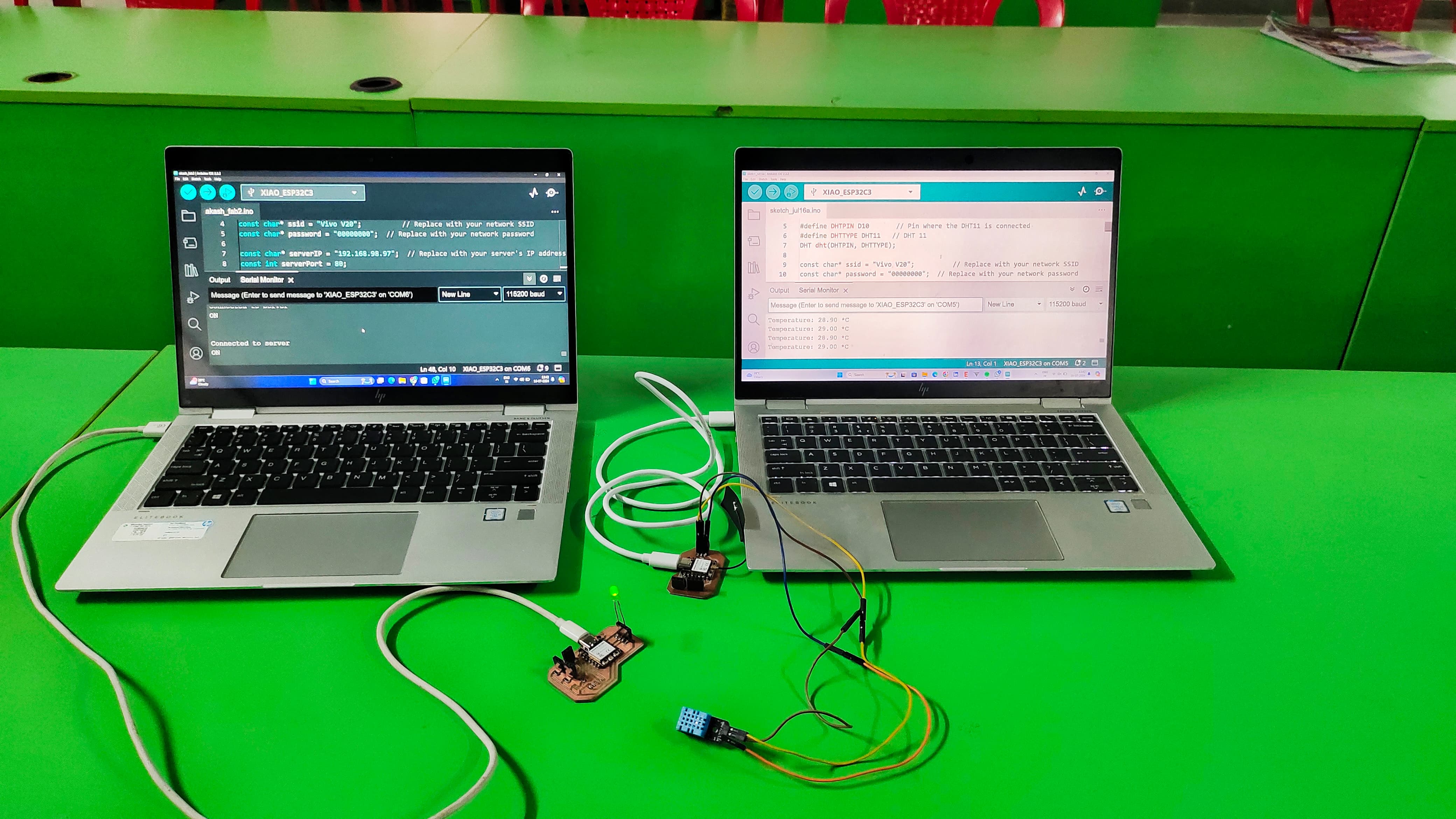
For this week's group assignmet I used two boards of Xiao's Esp32 C3. and I made wifi communication between these two boards.
1. Input Devices Board - Akash Mhais
2. Final Project Board - Siddhi Bodhe
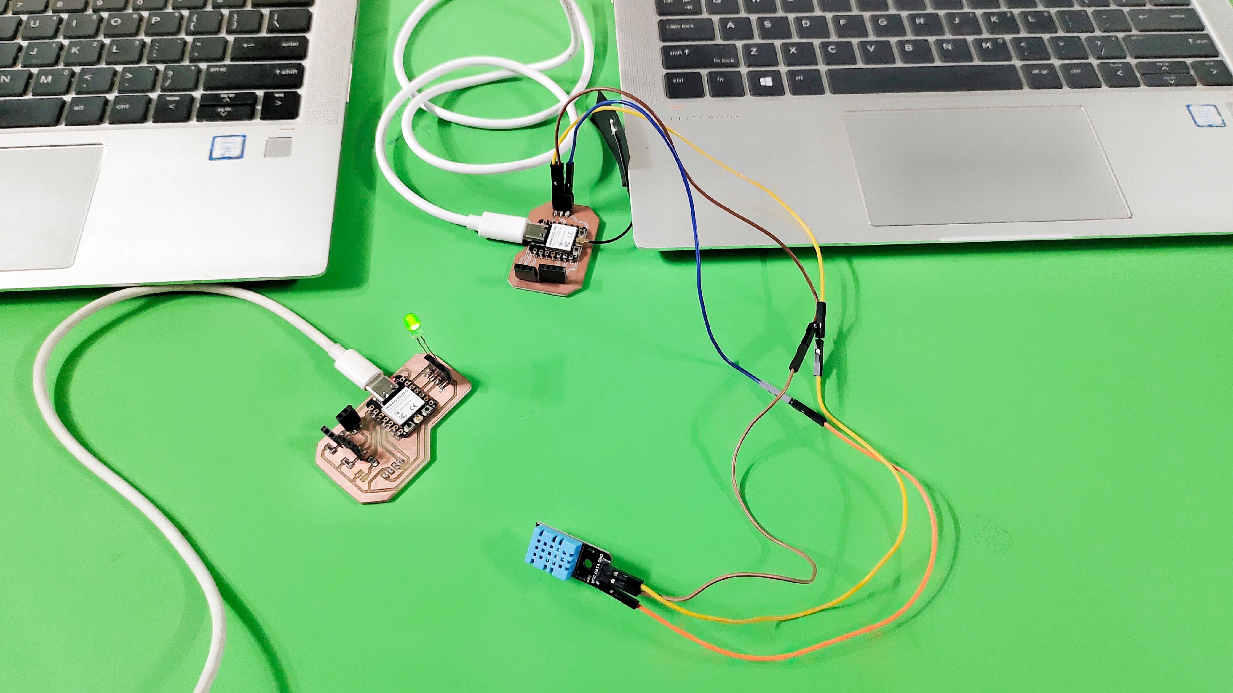
I used my board as a server board and connected to DHT11 sensor. The Second board is used as Client Board connected to the LED.
When the Temperature is goes above the 28 degree celcius then the led connected to the second board will turn on.
I used my Input Devices Board as a Server board, which is connected to the DHT11 Sensor.
Server Code (Reading DHT11 Sensor and Sending Data)
This code runs on the first Xiao ESP32 C3, which reads the temperature from the DHT11 sensor and sends a signal to the client if the temperature exceeds 28 degrees Celsius.
    #include < WiFi.h>

      #include < WiFiClient.h>

      #include < DHT.h>


      #define DHTPIN D10       // Pin where the DHT11 is connected

      #define DHTTYPE DHT11   // DHT 11

      DHT dht(DHTPIN, DHTTYPE);


      const char* ssid = "Vivo V20";          // Replace with your network SSID

      const char* password = "00000000";  // Replace with your network password


      WiFiServer server(80);


      void setup() {

        Serial.begin(115200);

        dht.begin();


        // Connect to Wi-Fi network

        WiFi.begin(ssid, password);

        while (WiFi.status() != WL_CONNECTED) {

          delay(1000);

          Serial.println("Connecting to WiFi...");

        }

        Serial.println("Connected to WiFi");

      // Print the IP address

        Serial.print("IP Address: ");

        Serial.println(WiFi.localIP());

        // Start the server

        server.begin();

      }


      void loop() {

        // Read temperature

        float temperature = dht.readTemperature();


        // Check if reading was successful

        if (isnan(temperature)) {

          Serial.println("Failed to read from DHT sensor!");

          return;

        }


        // Print temperature to Serial Monitor

        Serial.print("Temperature: ");

        Serial.print(temperature);

        Serial.println(" *C");


        // If temperature exceeds 28 degrees, send signal to client

        if (temperature > 28.0) {

          WiFiClient client = server.available();

          if (client) {

            client.println("ON");

            delay(1000);

            client.stop();

          }

        }


        delay(2000);  // Wait a bit before reading again

      }
#_Code_Explanation_:)
Includes and Definitions:
WiFi.h: Handles Wi-Fi communication.
WiFiClient.h: Allows the device to create a client for Wi-Fi communication.
DHT.h: Manages the DHT11 sensor.
DHTPIN: Defines the GPIO pin connected to the DHT11 sensor.
DHTTYPE: Defines the type of DHT sensor (DHT11 in this case).
DHT dht(DHTPIN, DHTTYPE): Initializes the DHT sensor.
Wi-Fi and Server Setup:
ssid and password: Wi-Fi credentials.
WiFiServer server(80): Creates a server on port 80 (HTTP).
Setup Function:
Serial.begin(115200): Initializes serial communication for debugging.
dht.begin(): Initializes the DHT sensor.
WiFi.begin(ssid, password): Connects to the specified Wi-Fi network.
WiFi.status() != WL_CONNECTED: Waits until the board is connected to Wi-Fi.
WiFi.localIP(): Prints the IP address of the board.
server.begin(): Starts the server.
Loop Function:
Reads the temperature from the DHT11 sensor.
Checks if the reading is valid.
Prints the temperature to the Serial Monitor.
If the temperature exceeds 28°C, it sends an "ON" signal to any connected client.
#_Server_Output_:)
I used my Siddhi's Board as a Client board, which is connected to the LED.
This code connects to the server and turns on an LED when it receives an "ON" signal.
            #include < WiFi.h>

              #include < WiFiClient.h>


              const char* ssid = "Vivo V20";          // Replace with your network SSID

              const char* password = "00000000";  // Replace with your network password


              const char* serverIP = "192.168.98.97";  // Replace with your server's IP address

              const int serverPort = 80;


              const int ledPin = 2;  // Pin where the LED is connected


              void setup() {

                Serial.begin(115200);

                pinMode(ledPin, OUTPUT);

                digitalWrite(ledPin, LOW);  // Make sure LED is off initially


                // Connect to Wi-Fi network

                WiFi.begin(ssid, password);

                while (WiFi.status() != WL_CONNECTED) {

                  delay(1000);

                  Serial.println("Connecting to WiFi...");

                }

                Serial.println("Connected to WiFi");

              }


              void loop() {

                WiFiClient client;

                if (client.connect(serverIP, serverPort)) {

                  Serial.println("Connected to server");


                  while (client.connected()) {

                    if (client.available()) {

                      String line = client.readStringUntil('\r');

                      Serial.println(line);


                      if (line == "ON") {

                        digitalWrite(ledPin, HIGH);  // Turn on the LED

                      } else {

                        digitalWrite(ledPin, LOW);   // Turn off the LED

                      }

                    }

                  }

                  client.stop();

                } else {

                  Serial.println("Failed to connect to server");

                }


                delay(500);  // Wait a bit before trying again

              }
#_Code_Explanation_:)
Libraries:
WiFi.h and WiFiClient.h for Wi-Fi functionalities.
Wi-Fi Credentials and Server Information:
ssid and password store the Wi-Fi network credentials.
serverIP stores the IP address of the server.
serverPort specifies the port number (80).
LED Pin:
ledPin specifies the GPIO pin connected to the LED.
Setup Function:
Initializes serial communication.
Sets up the LED pin as an output and ensures the LED is off initially.
Connects to the Wi-Fi network.
Loop Function:
Attempts to connect to the server using the specified IP address and port.
If connected, reads the data sent by the server.
If it reads "ON", it turns on the LED; otherwise, it turns off the LED.
If the connection to the server fails, it prints a message and retries after a delay.
#_Client_Output_:)
#_Final_Output_1:)
#_Final_Output_2:)
Click here to get more about the assignment.
Code : client.ino.
Code : server.ino.
Code : Receiver.ino.
Code : Transmitter.ino.