Input Devices:-
What is Input device? The name itself give an idea that the device which takes an input from environment called as input device. An input device is a hardware component that allows users to provide data and control signals to a computer or other electronic systems. These devices translate physical actions, such as typing on a keyboard, clicking a mouse, or touching a screen, into electronic signals that the system can understand and process. Input devices are essential for user interaction, enabling the input of information, commands, and controls necessary for operating the system. Common examples include keyboards for text input, mice for navigation, touchscreens for direct interaction, and sensors for detecting environmental changes. By converting human actions into machine-readable signals, input devices play a critical role in the functionality and usability of electronic systems.
Group Assignment
Click here to see group assignment in detail.
Individual Assignmment
In individual assignment, I designed PCB board which includes Input devices - MQ135 gas sensor and pressure sensor.
1) MQ135 gas sensor
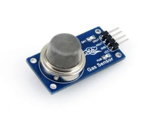
The MQ135 gas sensor is a versatile device used to detect a variety of gases in the air, making it essential for air quality monitoring systems. This sensor can measure the concentration of gases like ammonia, nitrogen oxides, alcohol, benzene, smoke, and carbon dioxide. It operates using a tin dioxide (SnO2) sensing layer, which exhibits lower conductivity in clean air. When the sensor is exposed to target gases, the interaction with the tin dioxide increases its conductivity. This change in conductivity is then converted into an electrical signal, which can be processed by a microcontroller or other devices to determine the concentration of the detected gases. The MQ135's wide sensitivity range makes it an ideal choice for applications requiring comprehensive air quality assessments.
2) Pressure Sensor
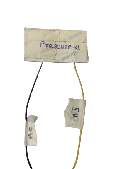
A pressure sensor made using Velostat is a simple, flexible, and cost-effective device for detecting and measuring pressure or force. Velostat, also known as Linqstat, is a conductive material that changes its electrical resistance when pressure is applied to it. The sensor is typically constructed by placing a piece of Velostat between two conductive layers. When pressure is exerted on the sensor, the resistance of the Velostat decreases, allowing more current to flow through the circuit. This change in resistance can be measured by a microcontroller or other electronic device to determine the amount of pressure applied. Velostat pressure sensors are widely used in applications such as wearable technology, robotics, and interactive surfaces due to their lightweight, flexible, and inexpensive nature.
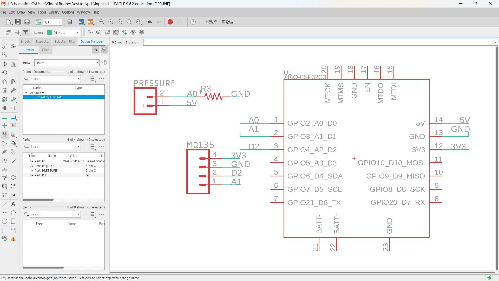
Here, I designed PCB Schematic in AutoDesk Eagle Software for PCB of input devices.
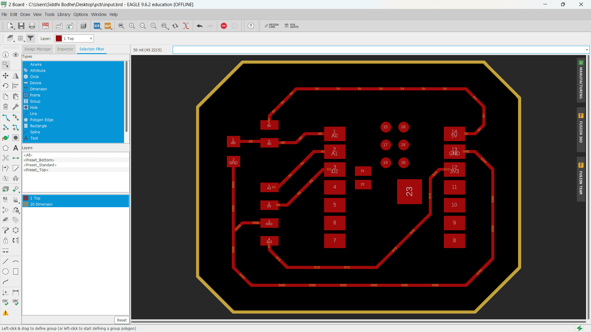
Here is the final design of PCB board for input devices.
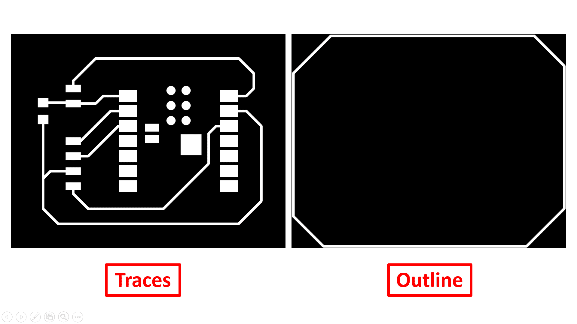
These are the PNG images of traces and outline exported for generating GCode for PCB Milling process.

Now, I used MIT Mods CE to generate GCode of image for PCB Milling process by inserting required parameters such as tool diameter, depth of cut and offset number.

Again, use same process to generate GCode of outline of PCB.
Here is the video of PCB Milling process of input devices PCB.
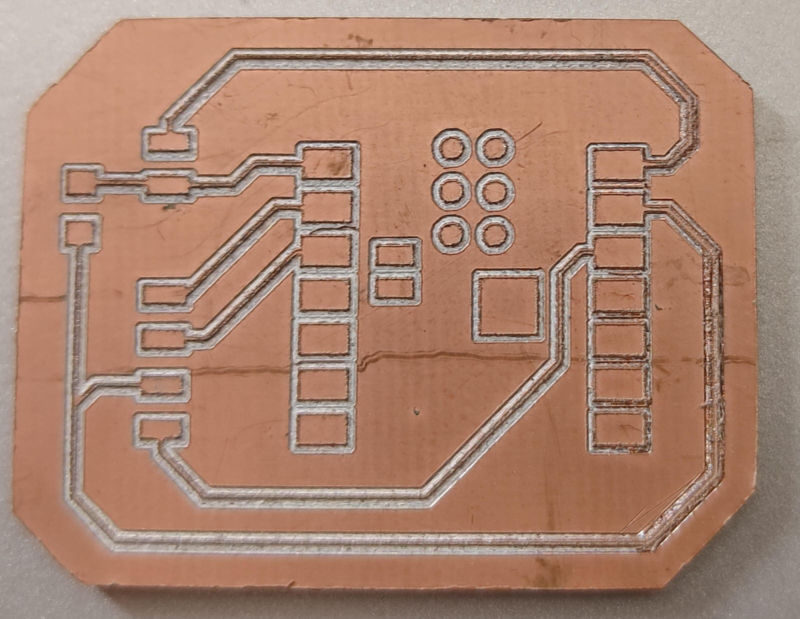
Here, I got the output.
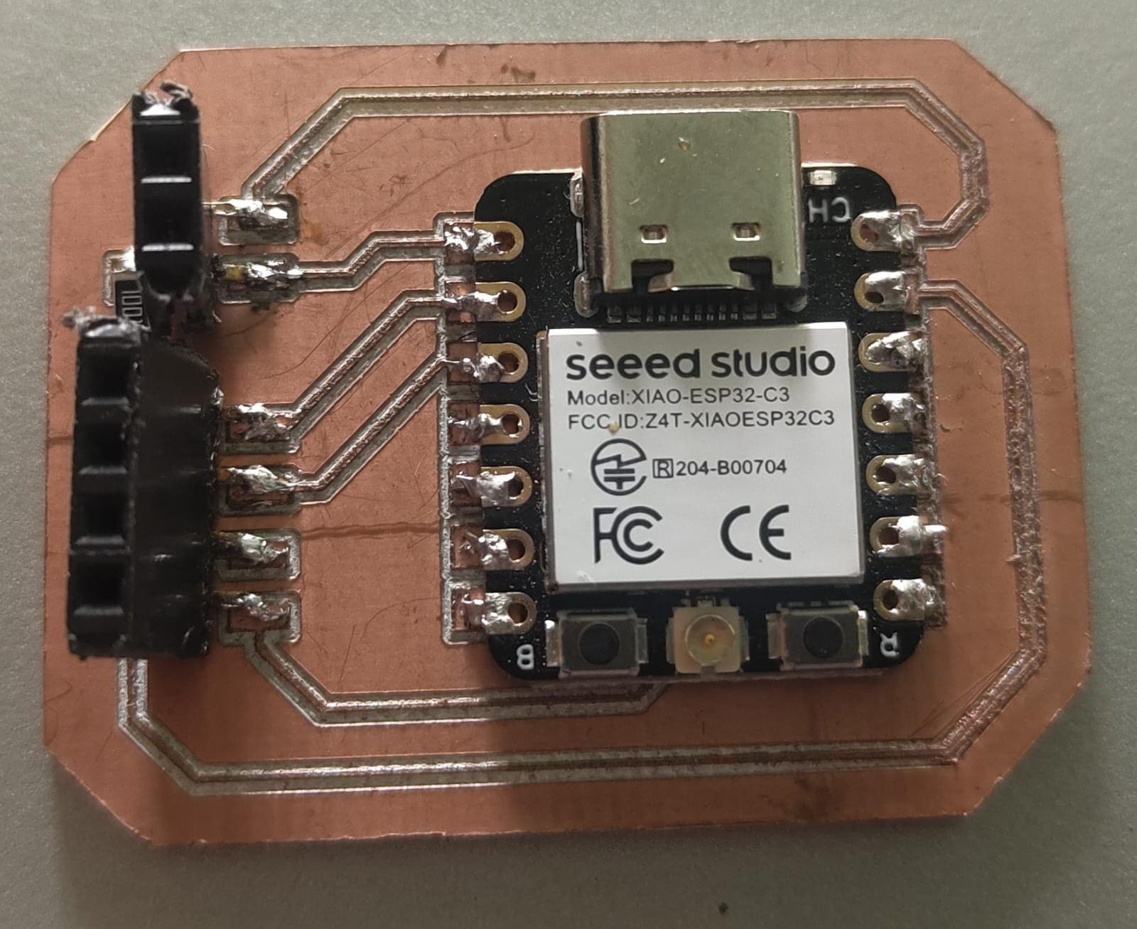
This is the glimpse after soldering the input deevice PCB. Finally, it is ready!
Now, its time for testing. Firstly, I tested all the devices separately with PCB board.
1) MQ135 gas sensor
Code:-
    const int sensorPin = A1; // Analog input pin connected to MQ-135

const int heaterPin = 2; // Digital output pin connected to MQ-135 heater (D2)


void setup() {

  Serial.begin(115200); // Initialize serial communication for printing data

  pinMode(heaterPin, OUTPUT); // Set heater pin as output

}


void loop() {

  digitalWrite(heaterPin, HIGH); // Turn on heater (adjust based on sensor datasheet)

  delay(1000); // Wait for heater to stabilize (adjust based on sensor datasheet)


  int sensorValue = analogRead(sensorPin);

  Serial.print("Sensor Value: ");

  Serial.println(sensorValue);


  digitalWrite(heaterPin, LOW); // Turn off heater (adjust based on sensor datasheet)

  delay(5000); // Wait before next reading

}
Code Explaination:-
To connect the MQ-135 gas sensor with the ESP32C3 microcontroller, I used the A1 pin for the analog output of the sensor and D2 for the heater control. The analog output pin of the MQ-135 is connected to A1, and the heater pin is connected to D2. In the setup function, I initialized serial communication at 115200 baud for monitoring data and set D2 as an output to control the heater. In the loop function, the heater is turned on by setting D2 to HIGH, and the system waits for 1 second to allow the heater to stabilize. After stabilization, the sensor value is read from A1 and printed to the serial monitor. The heater is then turned off by setting D2 to LOW, and the system waits for 5 seconds before taking the next reading. This cycle repeats indefinitely, allowing for periodic gas concentration measurements.
Output:-
2) Pressure Sensor
Code:-
        const int sensorPin = A0; // Analog input pin connected to pressure sensor


void setup() {

  Serial.begin(115200); // Initialize serial communication for printing data

}


void loop() {

  int sensorValue = analogRead(sensorPin);

  float voltage = sensorValue * (3.3 / 4095.0); // Convert raw value to voltage (assuming 3.3V reference and 12-bit ADC)

  // Apply calibration factor based on your sensor datasheet to convert voltage to pressure

  float pressure = voltage * calibration_factor; // Replace with your calibration calculation

  Serial.print("Pressure: ");

  Serial.print(pressure);

  Serial.println(" (your pressure unit)");

  delay(1000); // Wait 1 second before next reading

}
Code Explaination:-
To interface the pressure sensor with the ESP32C3 microcontroller, I connected the analog output pin of the pressure sensor to pin A0 on the ESP32C3. In the setup function, I initialized serial communication at a baud rate of 115200 for data logging. In the loop function, the sensor value is read from the A0 pin, which provides a raw analog value. This value is converted to a voltage by multiplying it by the ratio of the reference voltage (3.3V) to the maximum ADC value (4095 for a 12-bit ADC). The voltage is then converted to pressure using a calibration factor specific to the sensor, which should be determined based on the sensor's datasheet. The calculated pressure is printed to the serial monitor, followed by a delay of 1 second before taking the next reading. This cycle repeats indefinitely, providing continuous pressure measurements.
Output:-