Starting with some basic concepts regarding Electronic Production for better understanding.
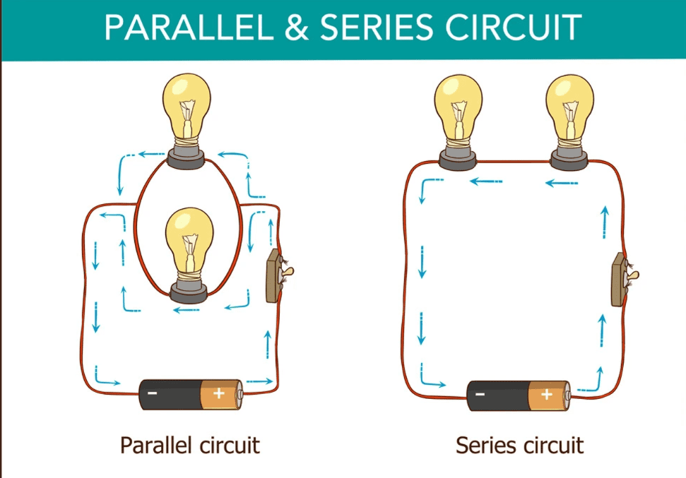
DC Series and Parellel Circuits
Basic Electronic Devices and Components:-
Group Assignment
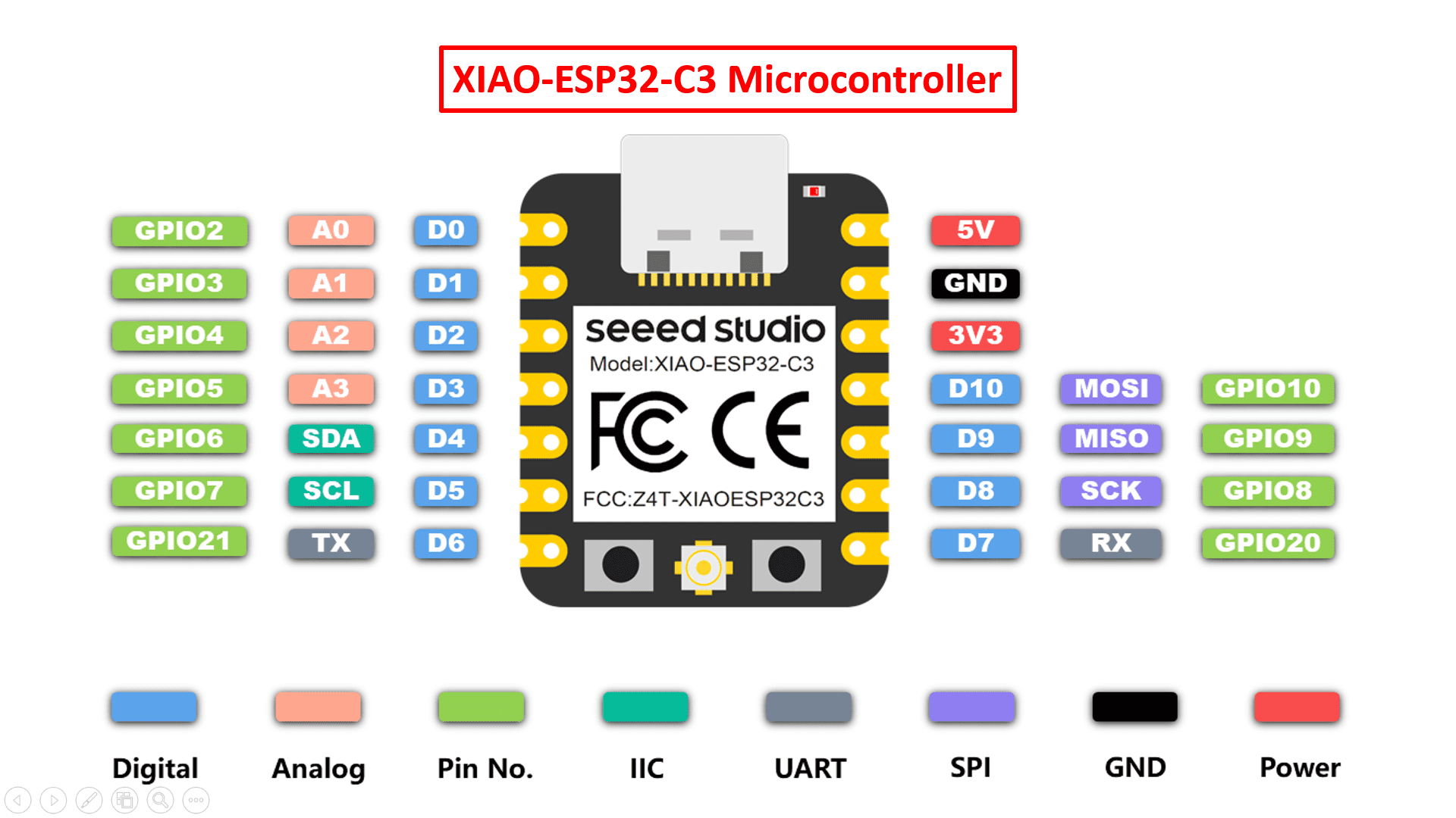
1) XIAO-ESP32-C3 microcontroller
I used AutoDesk Eagle software to design my PCB board.
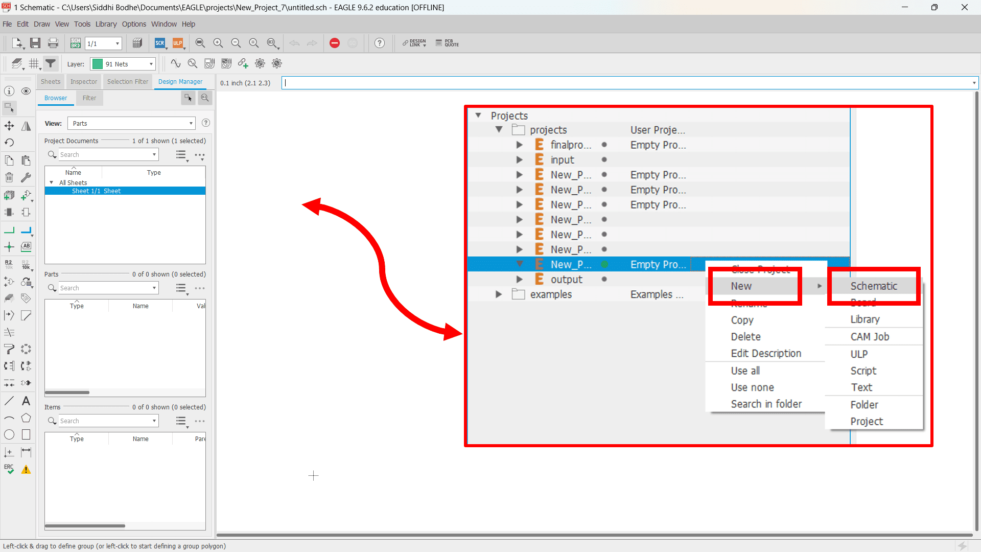
To create a new project, first go to the "File" which is located at the top-left side of the interface. Then, click on "New" and select "Project" to create a new blank projecct for our design work.
Now, a dropdown list of created project files is open. Click on "New" and select the "Schematic" to design the connecction diagram. Here, a new window is opened after hitting on "Schematic" option to design the PCB Schematic.
To design the PCB schematic, I have installed some libraries (connectors, resistors, switches, microcontroller,etc.) just by opening the library manager and adding the required libraries into the software.
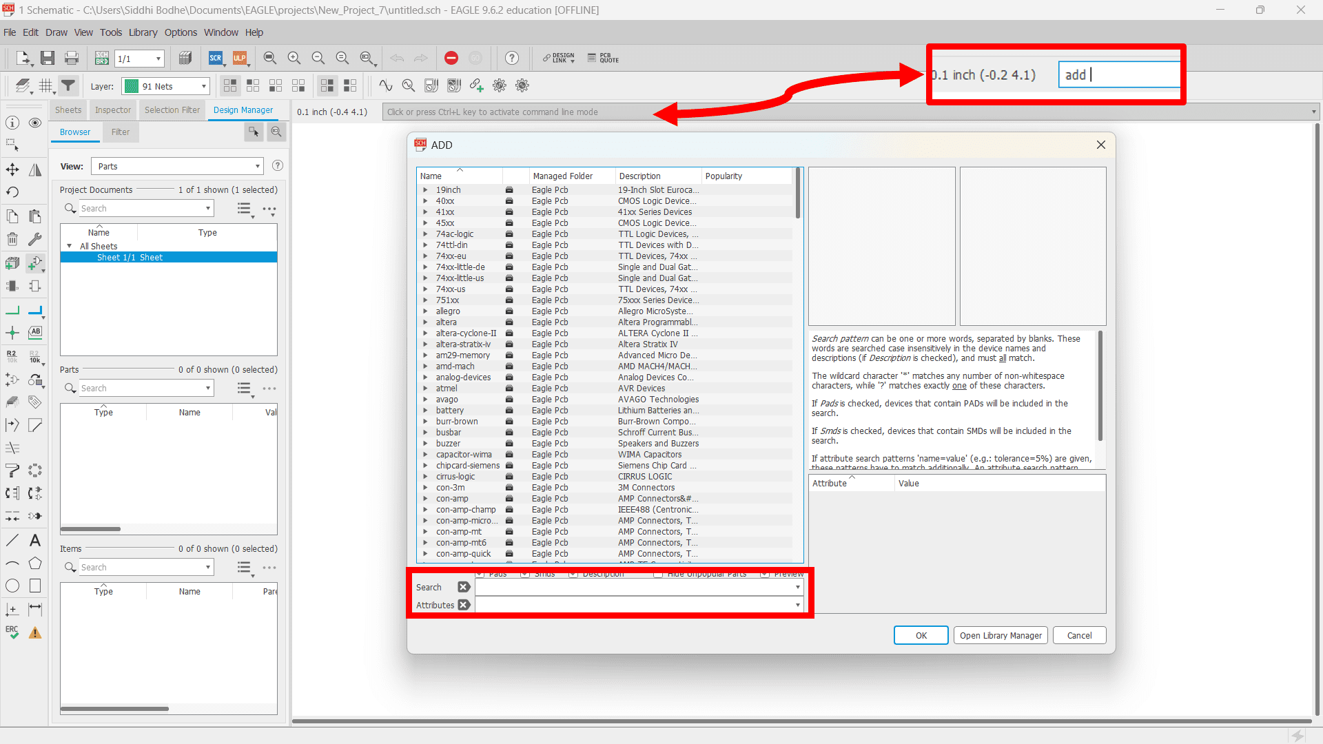
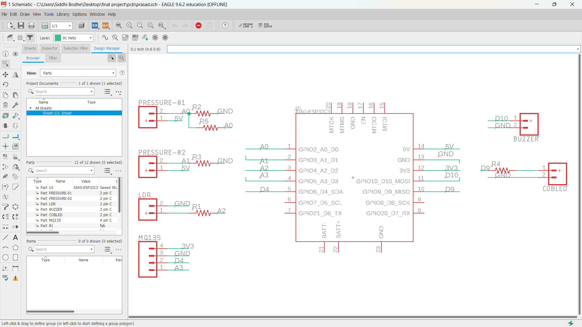
After the library installation process, I inserted all the electronic components that I want to use for my Final Project by typing "add" + Enter on command line at the header.
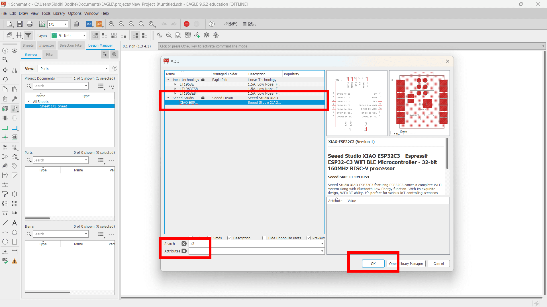
Here, I inserted XIAO-ESP32-C3 microcontroller using the same above process. Likewise, I inserted resistor, 2 pin connector, 4 pin connector in my schematic.
In schematic design, I used "select", "move", "rotate", "label", "route wire" commands to design the whole schematic of PCB board.
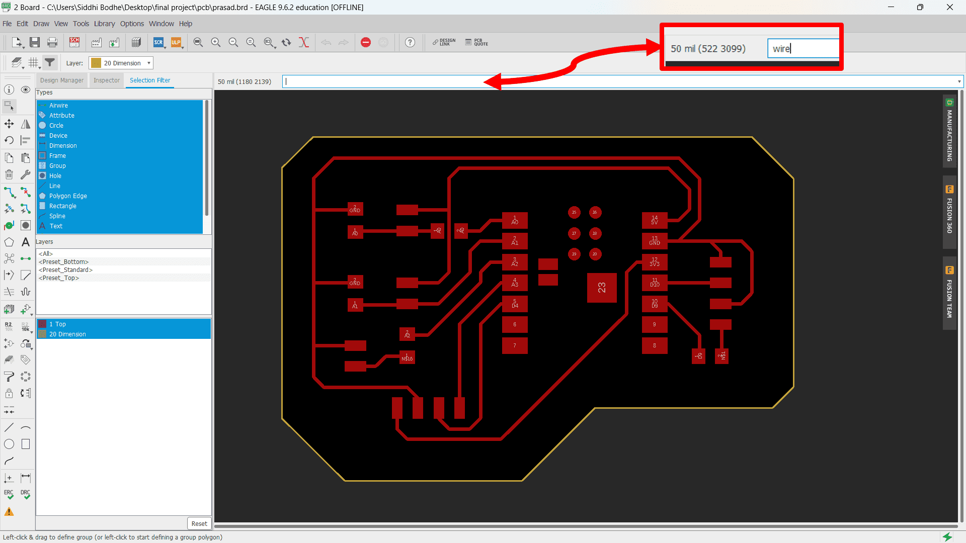
In board design, I used "select", "move", "rotate", "route wire of 16 mills" commands to designn my complete board same as schematic part.
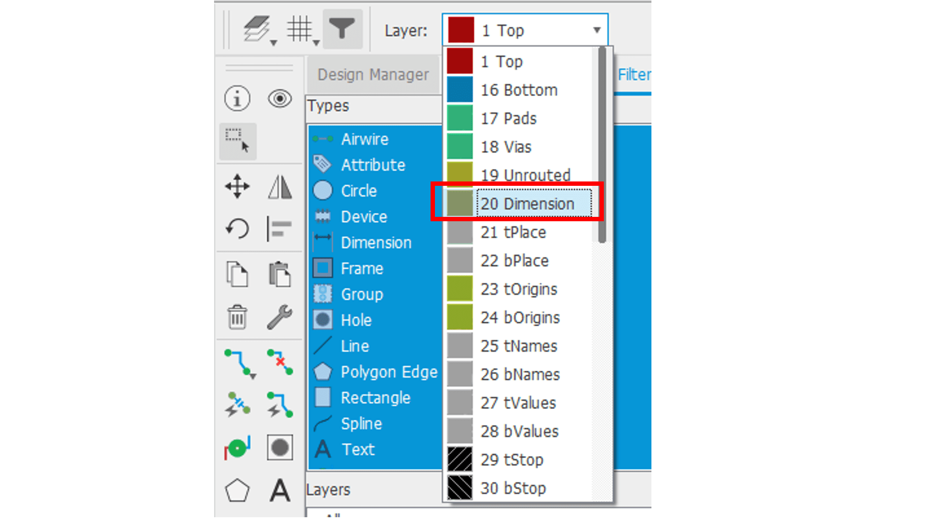
Then, select "20 dimension" layer from layer dropdown list to draw outline of the PCB board.
Here, again type "wire" in the command line to dtaw outline of PCB board. Finally, PCB is ready!
Now, I wanted to export separate PNG images for traces and outline. So, here I selected only "Top" layer from layer settings menu.
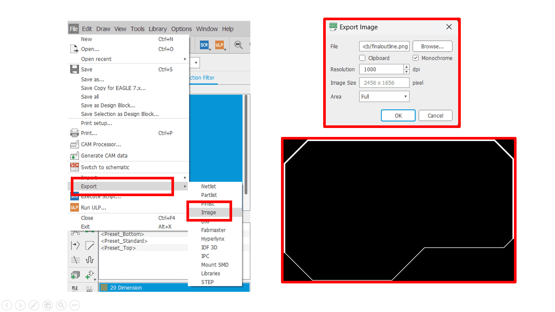
Now, only "top" layer is visible. Go to "file" located at the header, click on "export" and select "image" option. And export the image as per your required settings includes resolution, monochrome, area, etc.
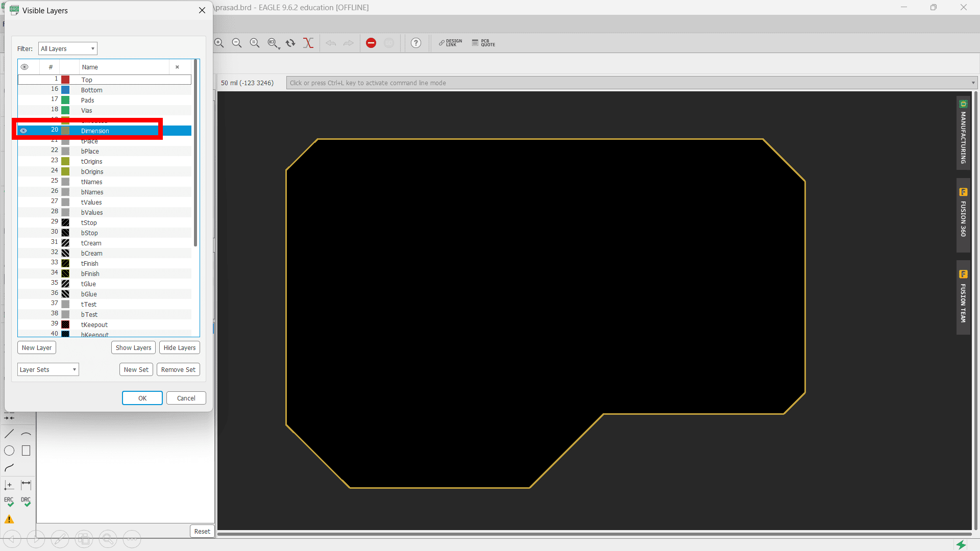
Now, select only "dimension" layer from layer setting to generate image of outline.
Again, use same process as traces to export the PNG immage of ouline.
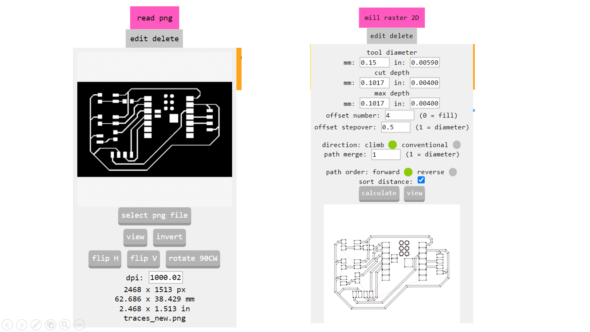
Now, I used MIT Mods CE to generate GCode of image for PCB Milling process by inserting required parameters such as tool diameter, depth of cut and offset nummber.
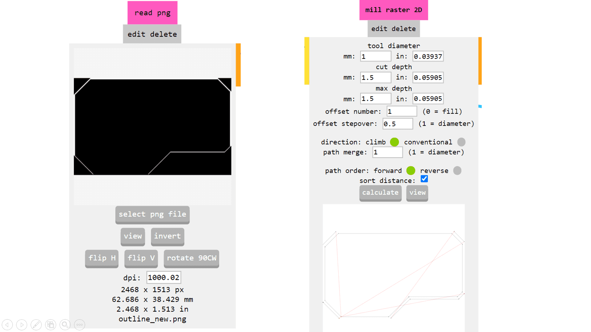
Again, use same process to generate GCode of outline of PCB.
Here is the video of PCB Milling process of my final project PCB.
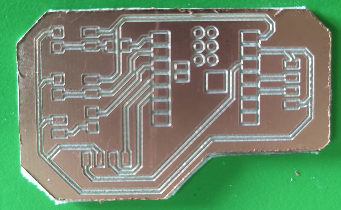
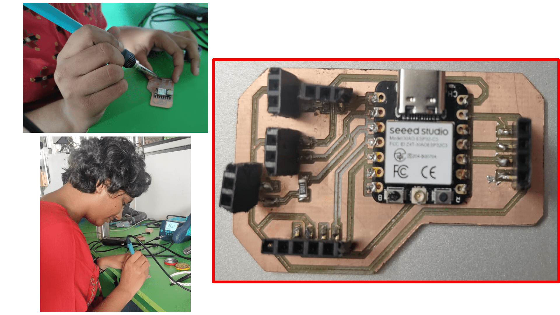
Here, I got the final output.
Then, I soldered my PCB Board and finally the board is ready.
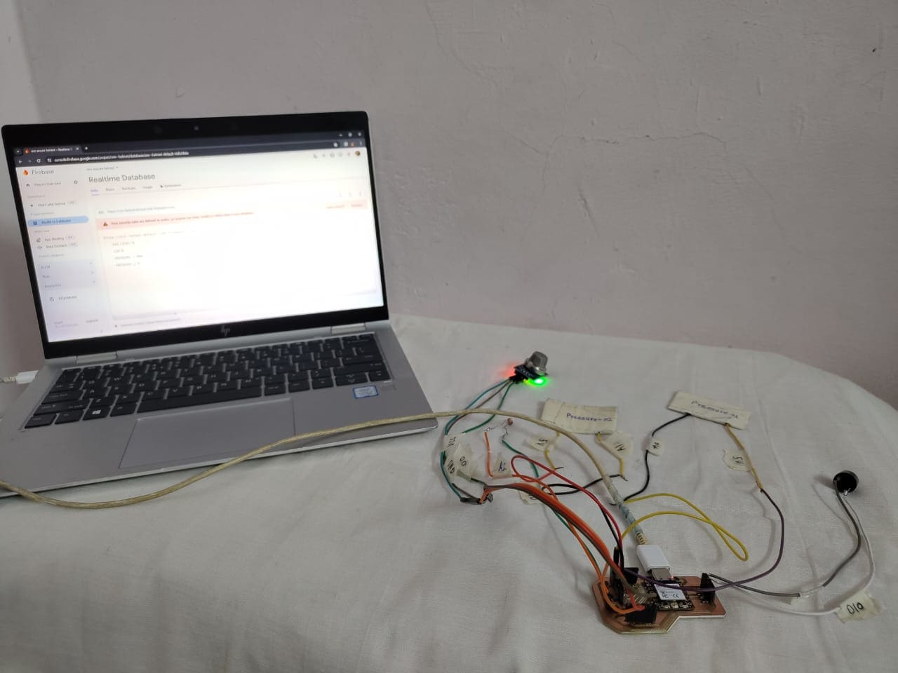
Here, I did testing of my board.
And finally, Its working!
Basics of Electronics-History
Electronics, a branch of physics and electrical engineering, focuses on understanding and manipulating electrons through electronic devices. Unlike traditional electrical engineering, which relies on passive components like resistance and capacitance, electronics employs active devices to control electron flow, such as amplification and rectification. This distinction enables electronics to achieve more sophisticated functions. The impact of electronics on society has been profound. It all began with the discovery of the electron in 1897, followed by groundbreaking inventions like the vacuum tube, diode, and triode. These innovations, pioneered by Ambrose Fleming and Lee De Forest, allowed for the amplification and detection of small electrical signals without mechanical means. This laid the foundation for practical applications, leading to the widespread adoption of technologies like commercial radio broadcasting and long-distance telephony by the early 1920s. As a result, electronics not only revolutionized communication but also found applications in diverse fields such as music recording, contributing to the rapid growth and development of modern society.
Click here to know more.
Starting with some basic terminologies regarding electronics before going for electronic devices.
1. Current
An electric current is like a stream of tiny charged particles, such as electrons or ions, moving through a wire or other conductor. It's like a flow of electricity. The rate at which these charged particles move through a surface is what we call electric current. These moving particles, called charge carriers, can be different depending on what the conductor is made of. For example, in wires, it's usually electrons, while in semiconductors, it could be electrons or something called holes. In substances like electrolytes or plasma, it's ions. We measure electric current in units called amperes, or "amps" for short. It's like counting how many charged particles pass through a point in a second. Electric current also creates magnetic forces, which are handy in things like motors and generators. In addition, it can cause heating, like in light bulbs, and emit electromagnetic waves, which are used in things like broadcasting information wirelessly.
There are two types of current- Alternating current and Direct current.
Alternating current refers to the direction electricity flows throughout the circuit is constantly reversing, i.e. it is in alternating direction. It has a frequency of 50Hz.
Direct current refers to electricity flows in one direction and has frequency of 0Hz.
Click here to know more.
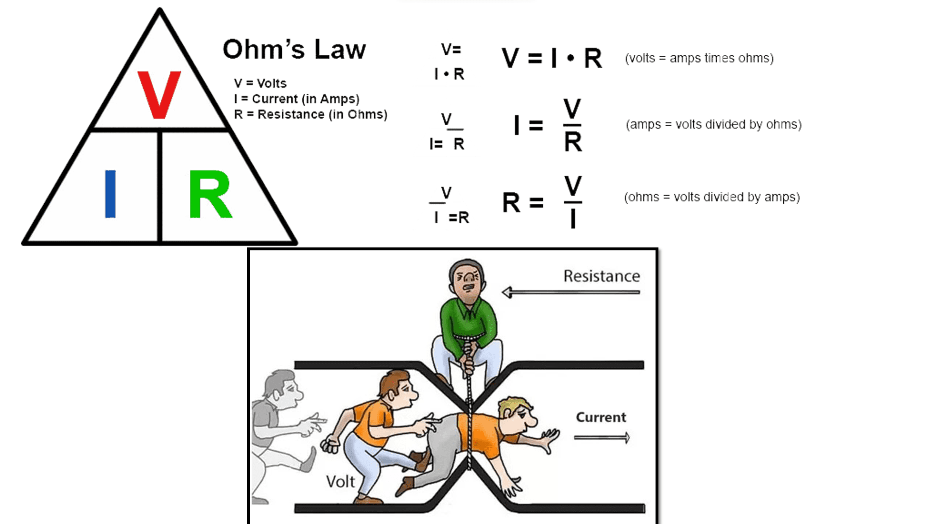
2. Voltage
Voltage, also known as electrical potential difference or electric pressure, is the difference in electric potential between two points. Think of it like the force that pushes electricity along a wire. In simpler terms, it's what makes electricity move from one place to another. We measure voltage in units called volts. It can be caused by different things, like the buildup of electric charge in a capacitor or the force generated by a generator. Sometimes, it's related to chemical reactions in batteries or even pressure or temperature changes in certain materials. Since voltage is about the difference in electric potential, it's a basic quantity that doesn't have a direction. We can use a tool called a voltmeter to measure voltage between two points in a system. Usually, one of these points is connected to a common reference, like the ground. Voltage can show us where energy is coming from or going to in a system, whether it's being used, lost, or stored.
Click here to know more.
3. Resistance and conductance
The electrical resistance of an object measures how much it resists the flow of electric current, similar to how friction slows down movement in mechanics. It's like an obstacle that electricity has to overcome. We measure resistance in ohms, with lower resistance meaning easier current flow. On the other hand, conductance, measured in siemens, is the opposite, showing how easily current flows through. Materials like rubber have high resistance, while metals have low resistance. This depends on their nature, but also their size and shape. For instance, long, thin wires have more resistance than short, thick ones. Superconductors are special because they have zero resistance. Ohm's law states that for many materials, voltage and current are directly proportional, making resistance constant. But in some cases, like with transformers or diodes, this relationship doesn't hold, and we use other measures like chordal or differential resistance.
Click here to know more.
In DC series circuits, components like resistors or bulbs are connected in a single loop, meaning the same current flows through each component. If one component fails, the circuit is broken. In contrast, DC parallel circuits have components connected across multiple paths, allowing different currents to flow through each. If one component fails, others continue to work. In series circuits, total resistance is the sum of individual resistances, while in parallel circuits, it decreases as more paths are added. Total voltage in series circuits equals the sum of individual voltages, while in parallel circuits, it remains constant across all components.
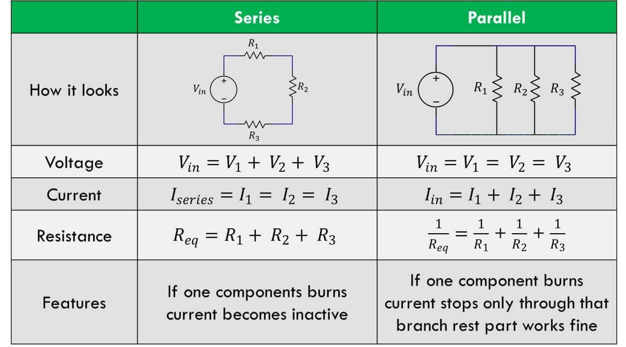
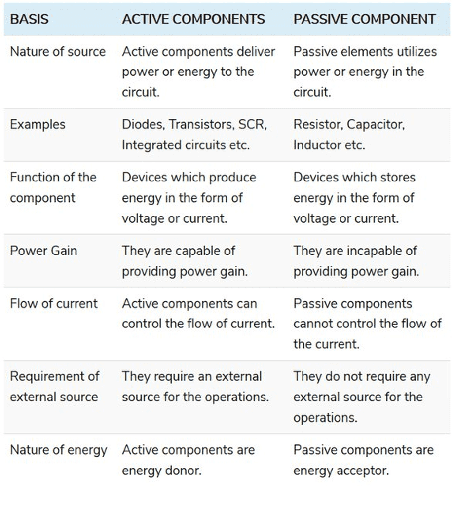
There are two types of electronic components - Active and Passive. Active components are those that require electricity or energy to work whereas Passive components are those that don't need any kind of elecctricity or energy to work.
Click here for detailed group assignment.
Individual Assignment
In individual assignment, I have to design my own PCB board, mill it, solder it and test it. So, I decided to design a PCB board for my final project as I finalized the components and microcontroller I want to used for my final project.
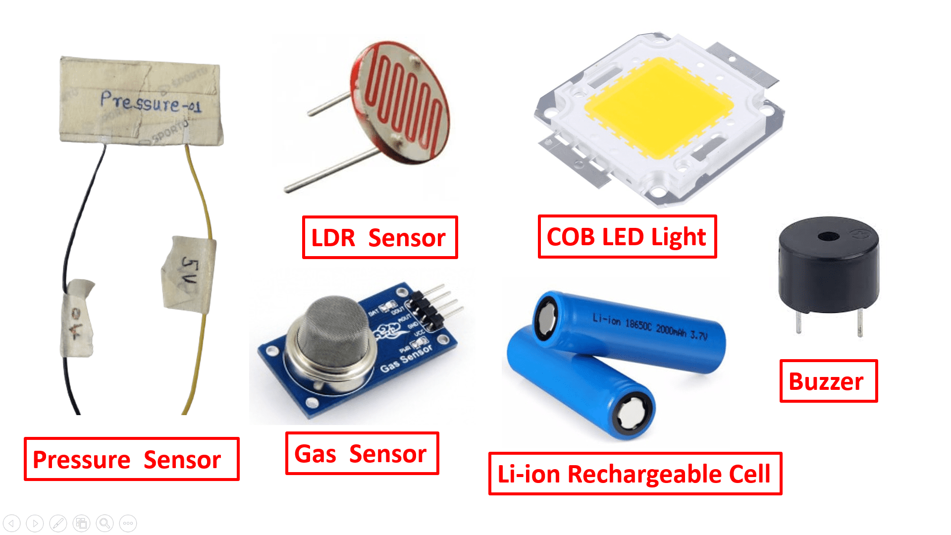
Here is the list of electronic components that I used for my Final Project -
2) Resistor
3) Pressure Sensor
4) MQ135 Gas Sensor
5) LDR Sensor
6) COB LED light
7) Buzzer