Computer Controlled Fabric Cutting Machine is also known as CNC cutting machine. Computer numerical control (CNC) is a manufacturing method that automates the control, movement and precision of machine tools through the use of preprogrammed computer software.
Assignments
Our task for this week is:
Group assignment:
Browse through the datasheet for your microcontroller
Compare the performance and development workflows for other architectures
Document your work to the group work page and reflect on your individual page what you learned
Individual assignment:
Write a program for a microcontroller development board to interact
(with local input &/or output devices) and communicate (with remote wired or wireless devices)
Group Assignment
The group assigment link is available here on the fabalab page.
Firstly, Whtat is Embedded system? An embedded system is a microprocessor- or
microcontroller-based system of hardware and software designed to perform dedicated functions
within a larger mechanical or electrical system.
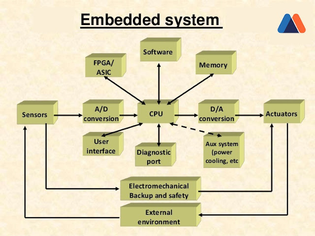
Basic Structure of an Embedded System
The basic structure of an embedded system includes the following components:
Sensor:The sensor measures and converts the physical quantity
to an electrical signal, which can then be read by an embedded systems engineer
or any electronic instrument.
A sensor stores the measured quantity to the memory.
A-D Converter: An analog-to-digital converter converts
the analog signal sent by the sensor into a digital signal.
Processor & ASICs:Processors assess the data to measure the output and store it to the memory.
D-A Converter: A digital-to-analog converter changes the digital data fed
by the processor to analog data
Actuator:An actuator compares the output given by the D-A
Converter to the actual output stored and stores the approved output.
Embedded systems play a significant role
in today's innovations. To gain insights into the historical evolution
of embedded systems and their future potential,
I recommend reading the full document on embedded systems available here.
What I learned in this from group assesment
First is to understand the microcontroller architectures and how they are differ.
Microcontroller architectures refer to the design and structure of microcontrollers,
which are integrated circuits that contain a processor core, memory, and input/output
peripherals on a single chip. These architectures define how the microcontroller processes
instructions, manages memory,
communicates with external devices, and performs various tasks in embedded systems.
The image above illustrates a sample PIC Microcontroller,
serving as a valuable tool for comprehending the fundamental architecture of microcontrollers.
This resource is
designed to aid everyone in grasping the intricacies of microcontroller design.
There are several types of microcontroller architectures,
each with its unique characteristics and advantages:
Harvard Architecture: In this type, separate memory spaces are used for data and instructions, allowing simultaneous access to both.
This architecture tends to be faster but may be more complex to program.
Von Neumann Architecture: Here, data and instructions share
the same memory space, making programming simpler but potentially
slower due to memory access limitations.
RISC (Reduced Instruction Set Computer): RISC architectures use a simplified set of i
nstructions, leading to faster execution and lower power consumption
compared to Complex Instruction Set Computing (CISC) architectures.
CISC (Complex Instruction Set Computing): CISC architectures have a more extensive set
of instructions, which can make programming more
straightforward but may result in slower execution and higher power consumption.
ARM Architecture: ARM processors are known for their energy efficiency and
are widely used in embedded systems and mobile devices.
They typically follow a RISC architecture.
Comparison of these microcontroller architectures
Von-Neumann Architecture vs Harvard Architecture
The following points distinguish the Von Neumann Architecture from the Harvard Architecture.
Von-Neumann Architecture
Harvard Architecture
Single memory to be shared by both code and data.
Separate memories for code and data.
Processor needs to fetch code in a separate clock cycle
and data in another clock cycle. So it requires two clock cycles.
Single clock cycle is sufficient, as separate buses are used to access code and data.
Higher speed, thus less time consuming.
Slower in speed, thus more time-consuming.
Simple in design.
Complex in design.
CISC and RISC
CISC is a Complex Instruction Set Computer.
It is a computer that can address a large number of instructions.
In the early 1980s, computer designers recommended that computers should use fewer instructions with simple constructs so that they can be executed much faster within the CPU without having to use memory.
Such computers are classified as Reduced Instruction Set Computer or RISC.
The following points differentiate a CISC from a RISC
CISC
RISC
Larger set of instructions. Easy to program
Smaller set of Instructions. Difficult to program.
Simpler design of compiler, considering larger set of instructions.
Complex design of compiler.
Many addressing modes causing complex instruction formats.
Few addressing modes, fix instruction format.
Instruction length is variable.
Instruction length varies.
Higher clock cycles per second.
Low clock cycle per second.
Emphasis is on hardware.
Emphasis is on software.
Control unit implements large instruction set using micro-program unit.
Each instruction is to be executed by hardware.
Slower execution, as instructions are to be read from memory and decoded by the decoder unit.
Faster execution, as each instruction is to be executed by hardware.
Pipelining is not possible.
Pipelining of instructions is possible, considering single clock cycle.
For a deeper understanding of microcontroller architectures, their applications,
and the advantages they offer, you can explore further details
here.
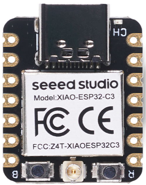
Microcontroller Datasheet, Seeed Studio ESP32C3 microcontroller
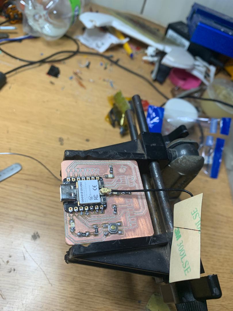
This week, I've been working on designing a PCB centered around the Seeed Studio
ESP32C3 microcontroller. This board will enable us to easily write and implement code
for interacting with various inputs and outputs. To kick off the coding process for this
microcontroller, I dedicated time to thoroughly studying its datasheet
and specifications to ensure a solid understanding before diving into programming.
From the Seeed Studio website,
obtained important information regarding the Seeed Studio ESP32C3 microcontroller.
Seeed Studio XIAO ESP32C3 is an IoT mini development board based on the Espressif ESP32-C3 WiFi/Bluetooth dual-mode chip. ESP32-C3 is a 32-bit RISC-V CPU.
It has excellent radio frequency performance, supporting IEEE 802.11 b/g/n WiFi, and Bluetooth 5 (LE) protocols. This board comes
included with an external antenna to increase the signal strength for your wireless applications.
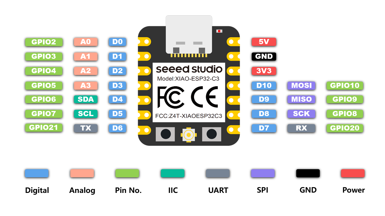
It also has a small and exquisite form-factor combined with a single-sided surface-mountable design.
It is equipped with rich interfaces and has 11 digital I/O that can be used as PWM pins and 4
analog I/O that can be used as ADC pins. It supports four serial interfaces such as UART,
I2C and SPI.
There is also a small reset button and a bootloader mode button on the board.
Features
Powerful CPU: ESP32-C3, 32bit RISC-V singlecore processor that operates at up to 160 MHz
Complete WiFi subsystem: Complies with IEEE 802.11b/g/n protocol and supports Station mode,
SoftAP mode, SoftAP + Station mode, and promiscuous mode
Bluetooth LE subsystem: Supports features of Bluetooth 5 and Bluetooth mesh
Ultra-Low Power: Deep sleep power consumption is about 43μA
Better RF performance: External RF antenna included
Battery charging chip: Supports lithium battery charge and discharge management
Rich on-chip resources: 400KB of SRAM, and 4MB of on-board flash memory
Ultra small size: As small as a thumb(20x17.5mm)
XIAO series classic form-factor for wearable devices and small projects
Reliable security features: Cryptographic hardware accelerators
that support AES-128/256, Hash, RSA, HMAC, digital signature and secure boot
5V - This is 5v out from the USB port. You can also use this as a voltage input but you must have some sort of diode (schottky, signal, power)
between your external power source and this pin with anode to battery, cathode to 5V pin.
3V3 - This is the regulated output from the onboard regulator. You can draw 700mA
GND - Power/data/signal ground
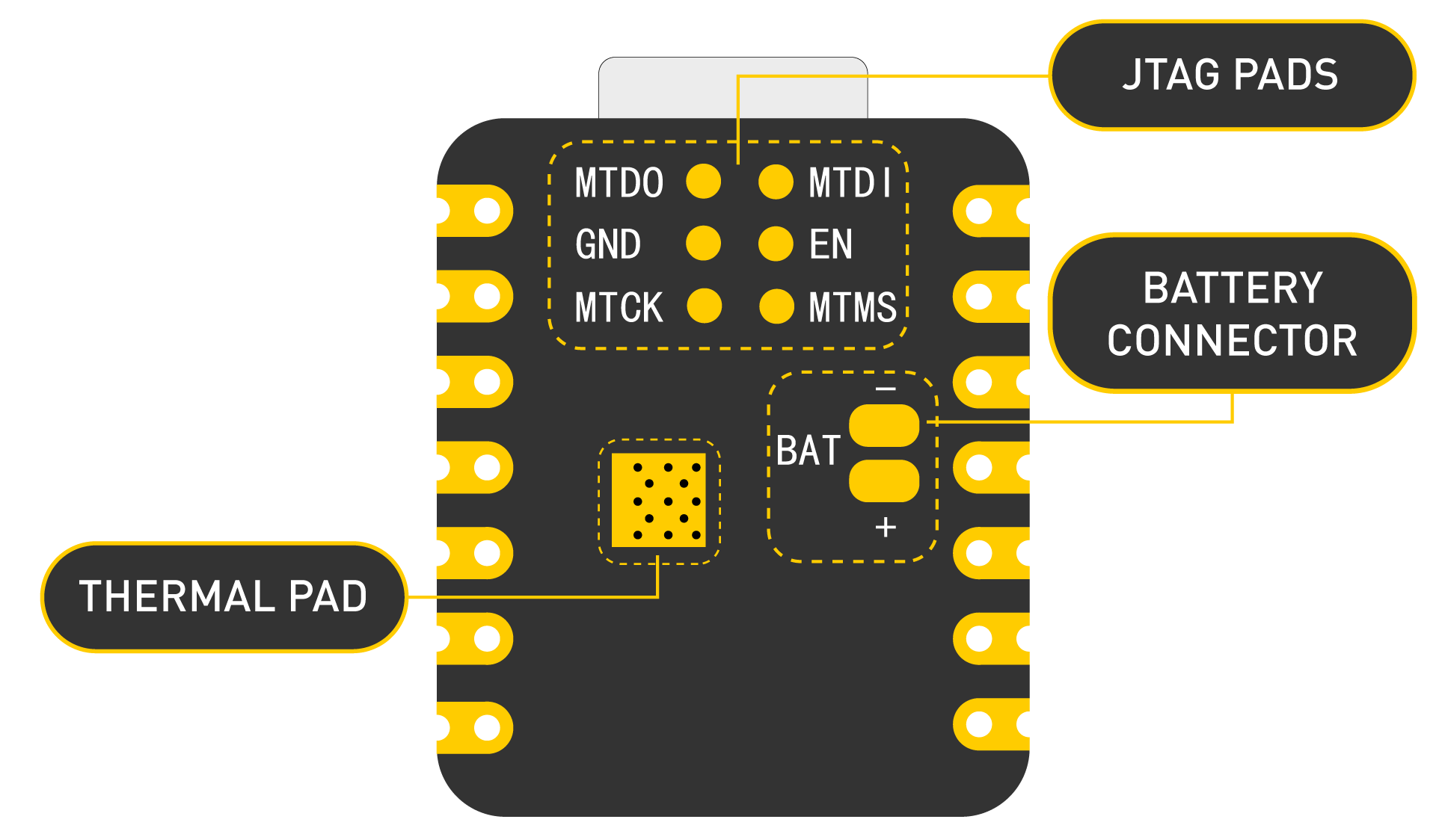
Strapping Pins
According to the chip manual of ESP32C3, GPIO2, GPIO8 and GPIO9 in the chip are Strapping Pins,
the high and low level configurations of these pins may allow the chip to enter into different
Boot modes, please pay attention to this point when you use these pins,
otherwise it may prevent your XIAO from uploading or executing the program all the time.
Production of PCB
To create the PCB for my first coding project,
I used PCB milling techniques. The design was created by Quentorres.
PCB Milling
PCB milling, also known as isolation milling, is a subtractive manufacturing
process used to create printed circuit boards (PCBs). In this process, a
CNC (Computer Numerical Control)
machine removes material from a copper-clad board to create the desired circuit patterns.
PCB milling is particularly useful for rapid prototyping, small-scale production, and custom PCB creation,
as it allows for quick turnaround times and flexibility in design changes.
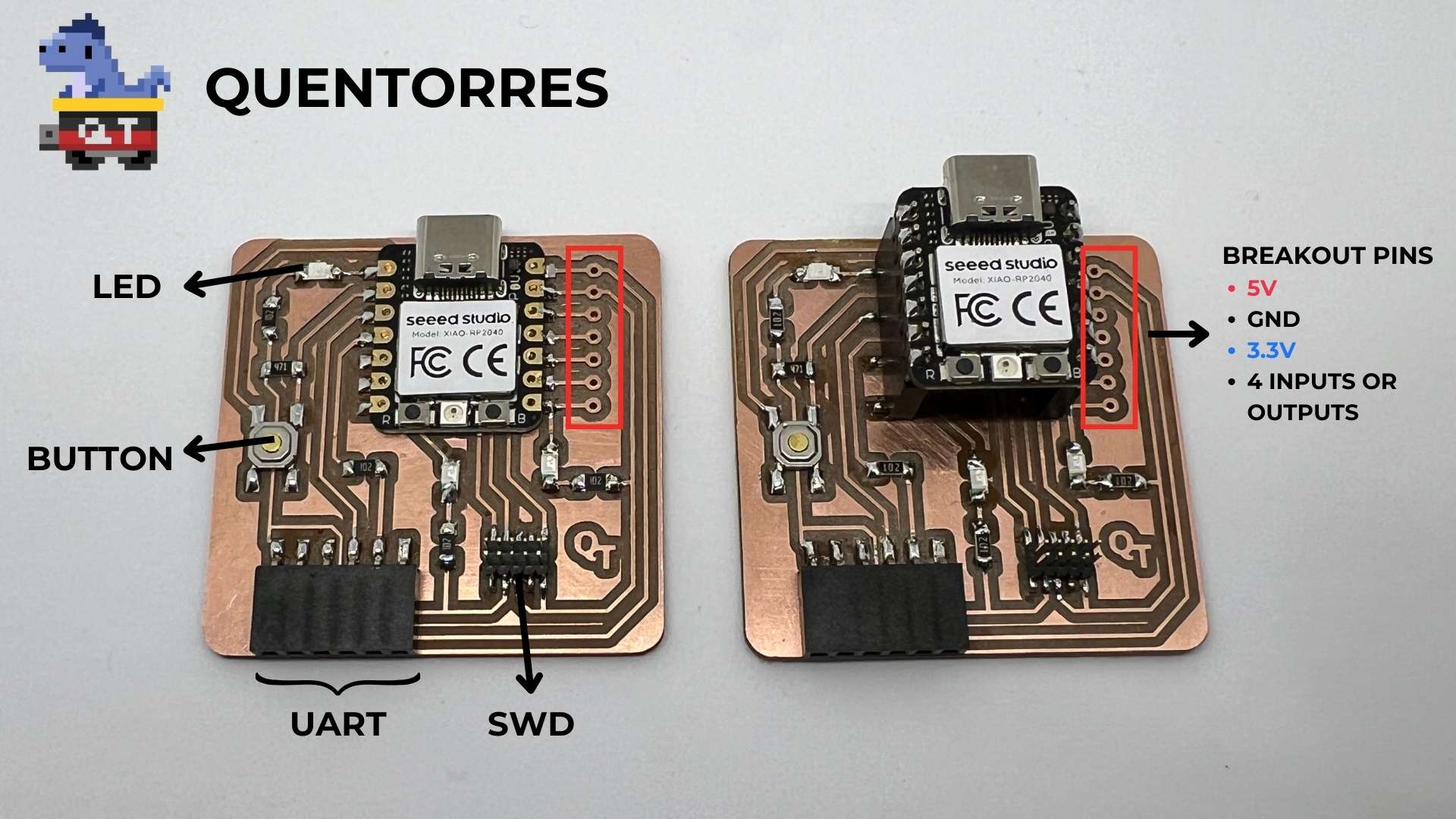
This board can program the new AVR Series 1 and 2 for example Adrianino
and the ARMs for example SAMDino. It also has a
button and an LED to learn to program in C, Rust, Go, Micropython...
It has breakout pins in case you want to connect other external elements.
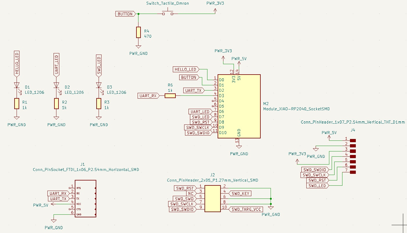
Schematic
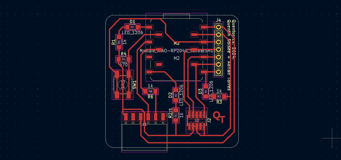
Board
Design FIles
If you want to produce the same board designed by Quentorres,
you can find the design file here.
Producstion
I began the process with engraving, selecting a 0.4 mm V-bit milling
cutter for this task. This specific bit was chosen due to its precision and
ability to create fine, detailed engravings, which is essential for ensuring
accurate and clean circuit paths on the PCB. Using a V-bit allows for greater
control over the depth and width of the engravings,
making it ideal for the intricate work required in PCB production.
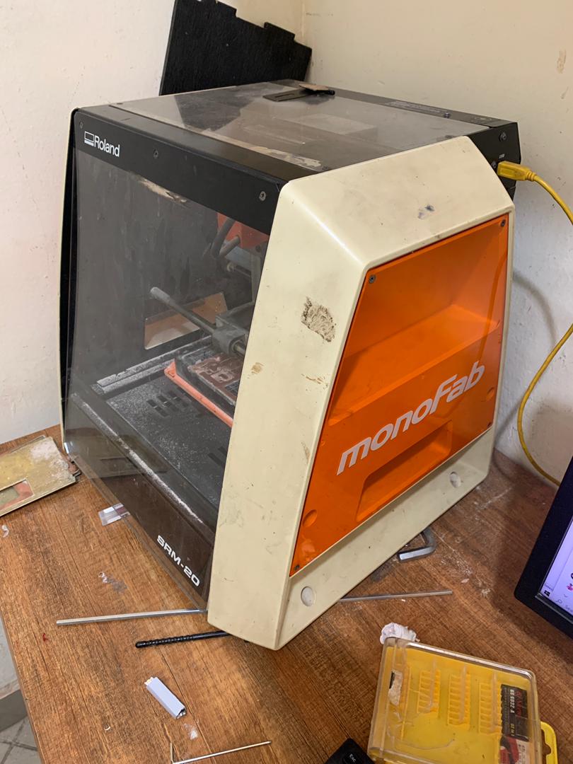
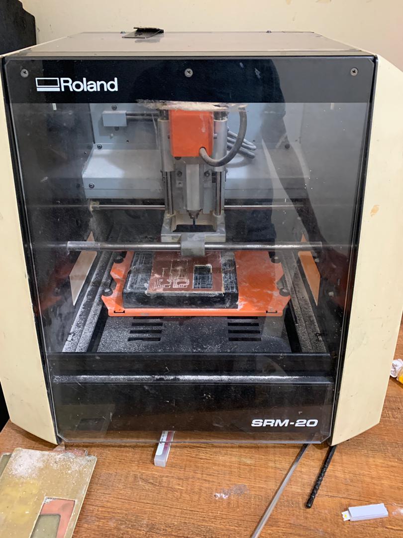
At our Fab Lab in Rwanda, we have a MonoFab machine that I use to engrave designs on PCBs.
This machine allows us to precisely follow the design
specifications from the provided files, ensuring high-quality and accurate PCB production.
I used the files "quentorres_interior.png" and "quentorres_traces.png," which you can see below.
You can find these files in Quentorres' GitHub account through the link provided above.
Setting MODs Fab
I might want to consider using MODs Fab for several reasons.
Firstly, MODs Fab offers a wide range of PCB fabrication options,
including advanced techniques like HDI (High-Density Interconnect) and flexible PCBs.
This means I can choose the best fabrication method suited to your project's requirements.
Secondly, MODs Fab often provides quick turnaround times, which can be crucial
if I am working on time-sensitive projects or need prototypes rapidly. Their
efficient production process and quality control
measures ensure that I receive reliable PCBs within a reasonable timeframe.
MODs Fab is known for its competitive pricing and transparent pricing structure.
I can easily estimate costs based on your PCB specifications and order volume,
allowing me to stay within budget without compromising on quality.
Locate the Mods Fab link to initiate and configure the settings for generating G-code compatible with the Monofab machine, enabling efficient production. Additionally, ensure the G-code parameters
match the Monofab machine's specifications for seamless execution and optimal results. Click here
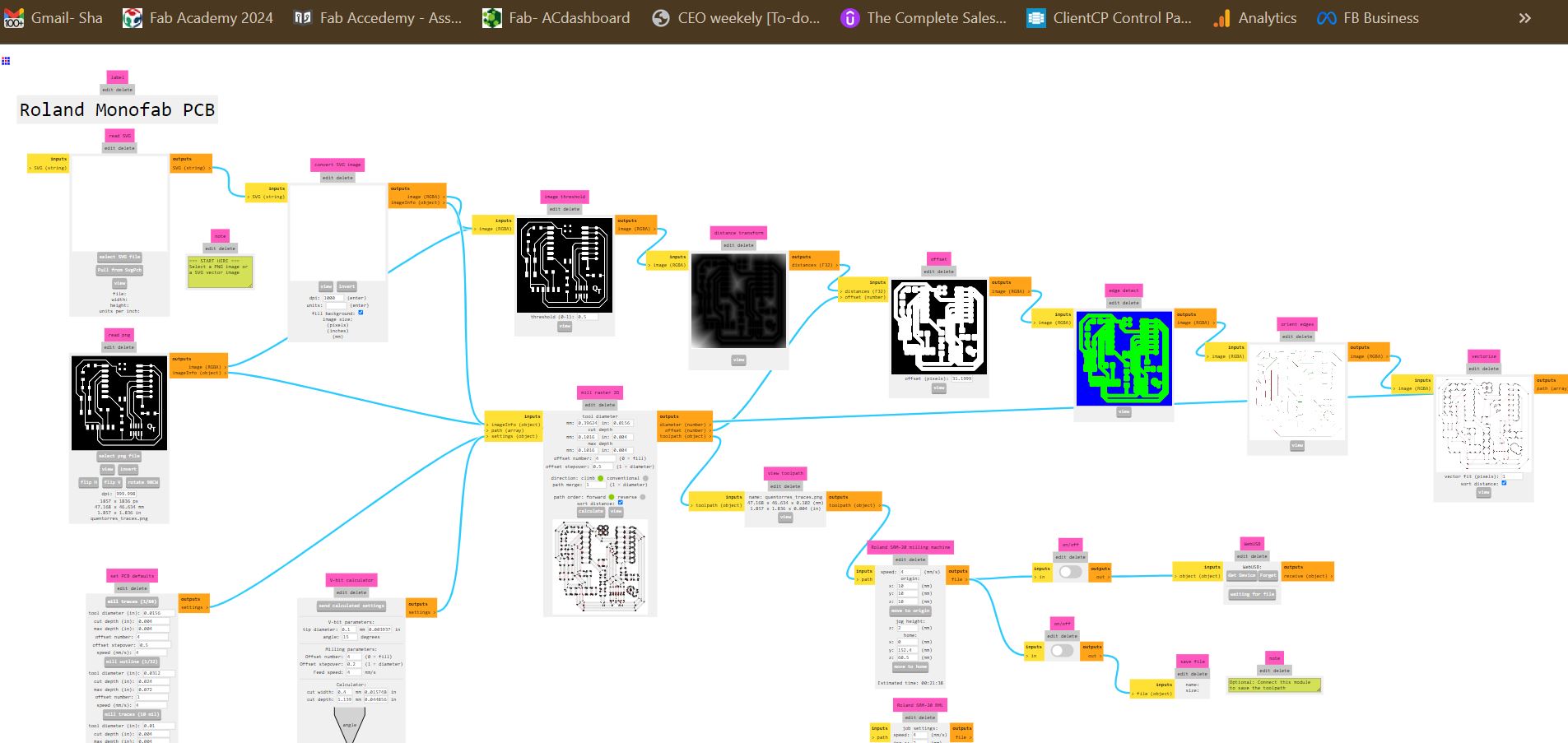
I followed the standard procedure for converting the design to G-code,
as taught in our electronics production class. Specifically,
I utilized the open-source program and selected the SRM 20 Roland machine,
utilizing the mill 2D PCB program in mods. Within the program,
I loaded the image for traces and set the mill raster cell parameters as follows: Tool diameter: 0.3962 mm,
Cut depth and max depth: 0.1016 mm,
Offset number: 2.5
These settings were chosen to ensure precise milling and accurate reproduction of the PCB design.
File to print
Setup Monofab Machine
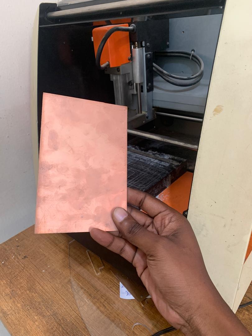
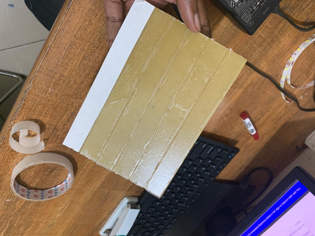
To set up the Monofab machine for PCB production, I selected copper as
the material due to its conductivity and durability. I used double-sided
tape to secure the copper sheet onto the machine's bed, ensuring stability during
the milling process. For cutting and engraving, I utilized V bits and Endmill tools,
which are ideal for precise PCB fabrication. The next steps involved carefully applying
the double-sided tape to the copper material, positioning it securely on the bed,
and inserting the chosen tool (V bit) into the machine's collet for precise milling operations.
selecting the PCB I have to use in Monofab Machina as you se above image
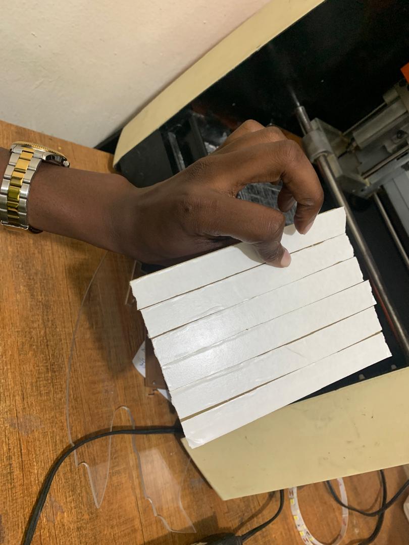
Apply double sided tape on my PCB
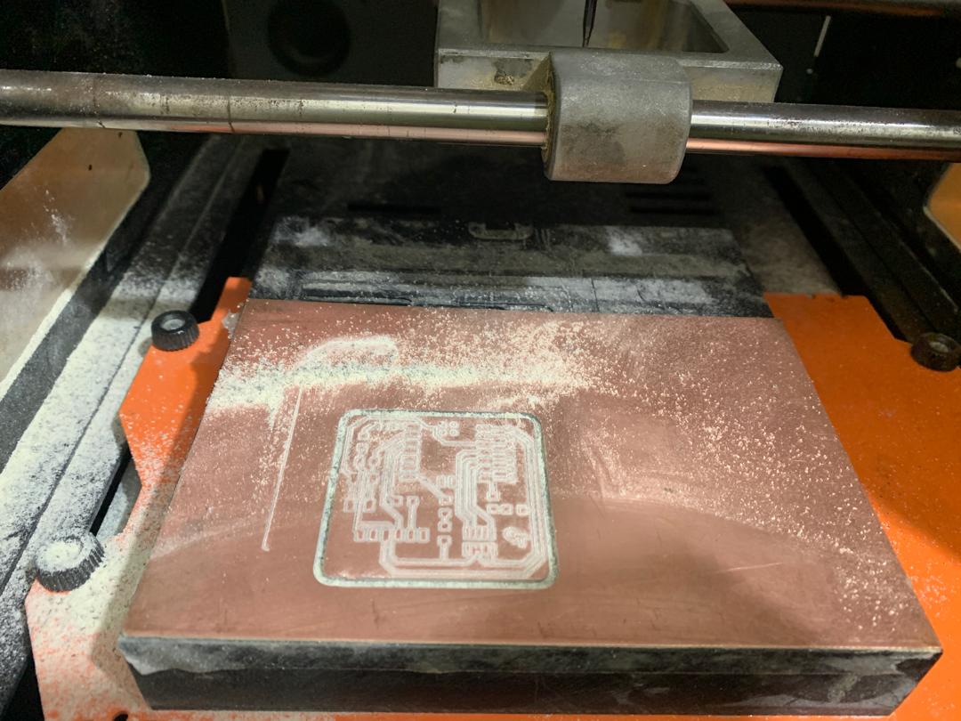
Starting to produce the pcb
Setting up Monofab machine
The Monofab machine features the Vpanel Roland SRM-20 controller,
which we used to load files generated by the Mods Fab tool for our PCB milling project.
Setting up the machine involved configuring the XY and Z axes.
For the XY axis, we navigated to the Move section and clicked on the XY
button under TO ORIGIN. This action positioned the machine at the origin of
the last work performed. However, for our project, we needed a different origin point, so we manually moved the axis to our desired location.
Once in place, we set the XY origin point by clicking on Set Origin Point.
Regarding the Z axis, we followed the procedure taught in our class.
After inserting the tool into the collet, we lowered it with the machine
until it was close to the PCB surface. By loosening and then retightening the collet,
we secured the tool at the desired Z-axis position.
Clicking the Z button under Set Origin Point finalized the Z-axis setup.
To load files, we clicked on "cut," which opened a window.
We then selected "delete all" to clear any previous work,
followed by "add" to directly access the generated files.
After opening the files, clicking on "output" initiated the milling process,
and the machine began working promptly.
With the Monofab machine set up, I'm all set to begin engraving my PCB
and finalize its design. Next, I'll proceed with soldering various components onto it.
You can check out this
video to see how the machine accomplishes this process. It's fascinating to watch!
Output PCB
Before soldering, preventing unexpected short circuits
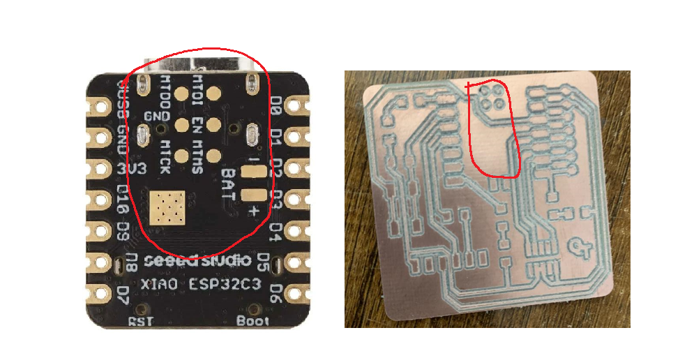
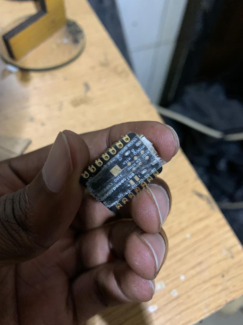
Before soldering my PCB and attaching the XIAO board, I applied simple techniques to avoid short circuits. As shown in the image below, the XIAO board has surface copper areas that could easily create short circuits when connected to my PCB.
The XIAO board has exposed copper areas that can come into contact with the PCB, increasing the risk of short circuits.
To prevent short circuits, I applied a thin layer of glue to the surface copper areas of the XIAO board before soldering. This insulating layer ensures that the copper does not directly touch the PCB, thereby avoiding potential short circuits.
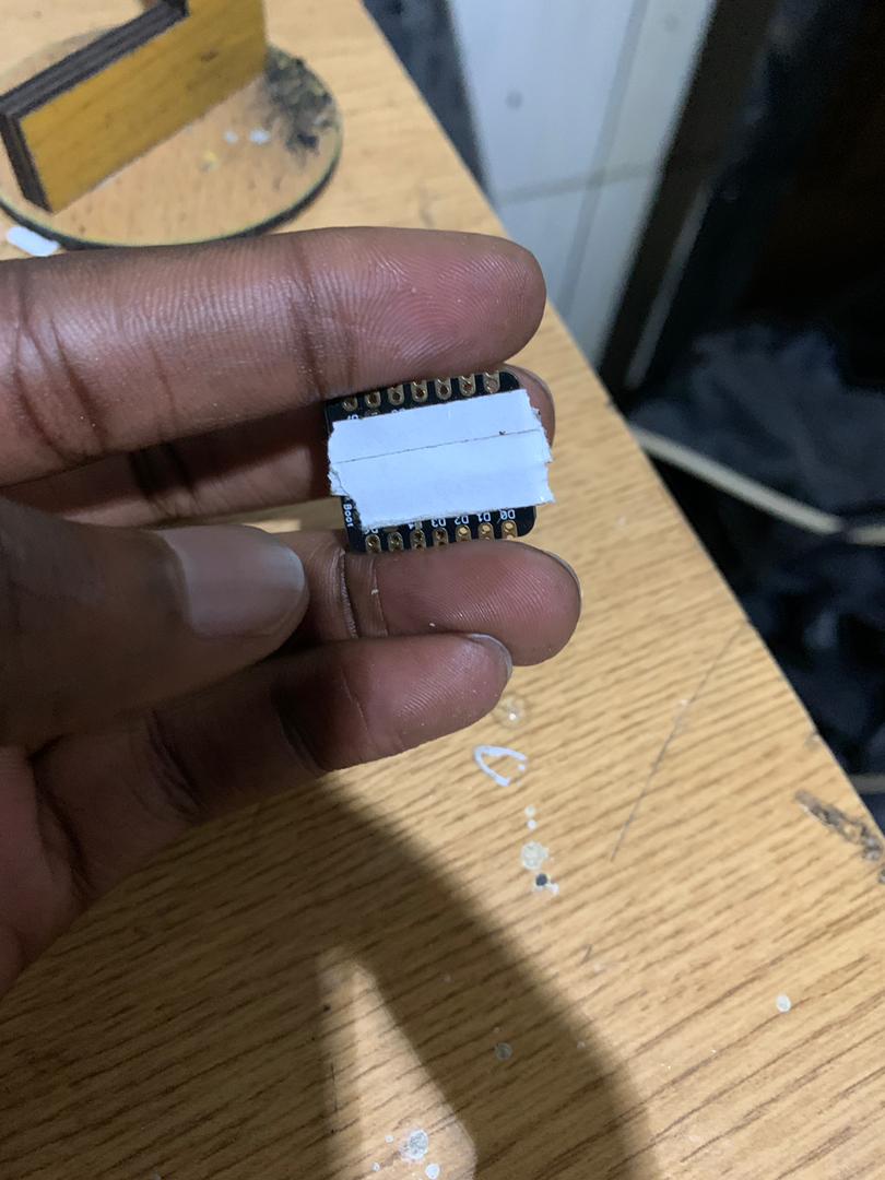
Other methods, such as using insulating tape or a conformal coating, can also be effective in preventing short circuits.
After applying the glue and ensuring it was dry, I carefully soldered the XIAO board to the PCB. The insulating layer provided an extra measure of safety against short circuits.
This image shows the XIAO board with glue applied to the surface copper areas. This simple step can significantly reduce the risk of short circuits when attaching the board to the PCB.
I added the double sided tap to privent the short circuit
Starting soldering the components
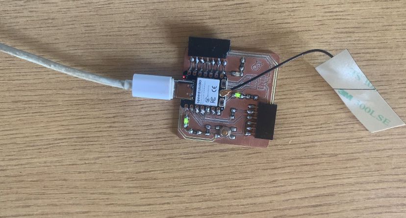
Finished board
Write a program for my microcontroller
As I have experience in Arduino programming, I decided to work with the
Seeed studio ESP32C3 board programmed through Arduino IDE using the C++ language.
The first step involves downloading Arduino IDE and then proceeding with the installation process,
which can be found here.
This IDE provides a user-friendly environment for writing and
uploading code to the ESP32C3 board, making it easier to develop and test projects.
I embarked on coding to control the LEDs connected to the development board,
intending to test its capabilities. To start, I launched Arduino IDE 2.0,
equipped with various boards and libraries. Initially, I sought to add additional
boards by navigating to File->Preferences and inputting the URL.
However, I couldn't find the XIAOESP32C3 board there.
Undeterred, I navigated to the left-hand corner's boards manager within Arduino IDE.
Here, I searched for "esp32" and installed the ESP32 by Espressif Systems.
Once installed, I proceeded to configure my specific board, the XIAOESP32C3.
I clicked on "Tools" in the toolbar, then selected "Boards," followed by "ESP32,"
and finally clicked on "XIAOESP32C3" to configure its settings.
After connecting my board to the computer, I had to select the appropriate port by navigating to
Tools in the toolbar. Then, I scrolled to the Ports section and activated the port where the
board was installed.
This step is crucial for successful connection and operation.
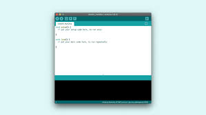
In the Arduino software, we typically work with three main parts:
Sketch/Code: This is where you write and edit your program using the Arduino programming language.
Setup Function: This part of the code is executed once when the board starts or resets.
It's where you initialize variables, pin modes, and other setup tasks.
Loop Function: After the setup, this function runs repeatedly, executing the main logic of your program.
It's where you put the instructions you want the board to carry out continuously.
After connect my board to the compute, I had to choose first the port by
clicking on Tools in the toolbar, then scroll to ports,
then depending on what port it is installed on,
then activate the ports on which it's connected to,
so after connecting and running, so in the arduino we have three main parts:
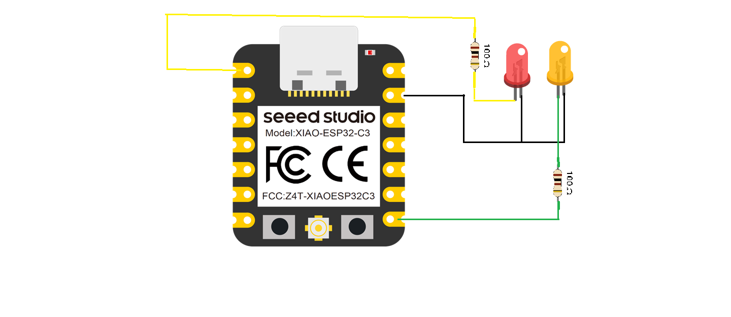
ESP32C3 wiring
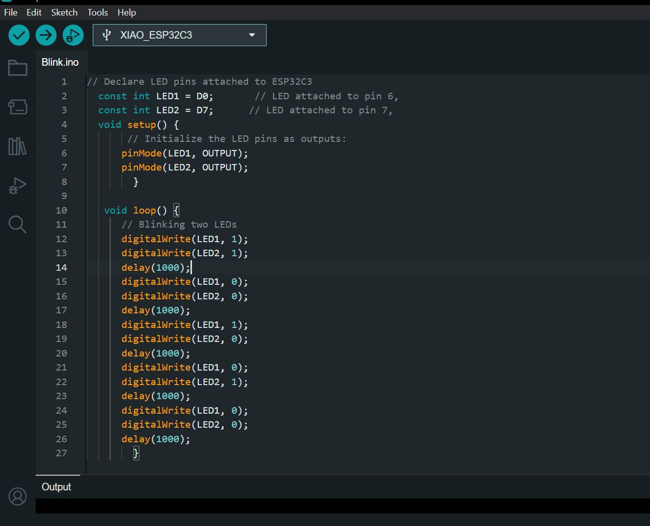
Blink Code
                    // Declare LED pins attached to ESP32C3
  const int LED1 = D0;       // LED attached to pin 6,
  const int LED2 = D7;      // LED attached to pin 7,
  void setup() {
       // Initialize the LED pins as outputs:
      pinMode(LED1, OUTPUT);
      pinMode(LED2, OUTPUT);
        }

   void loop() {
      // Blinking two LEDs
      digitalWrite(LED1, 1);
      digitalWrite(LED2, 1);
      delay(1000);
      digitalWrite(LED1, 0);
      digitalWrite(LED2, 0);
      delay(1000);
      digitalWrite(LED1, 1);
      digitalWrite(LED2, 0);
      delay(1000);
      digitalWrite(LED1, 0);
      digitalWrite(LED2, 1);
      delay(1000);
      digitalWrite(LED1, 0);
      digitalWrite(LED2, 0);
      delay(1000);
        }