Week 7
COMPUTER-CONTROLLED Machining
Our task for this week is:
Group assignment:
- Complete your lab’s safety training
- Test runout, alignment, fixturing, speeds, feeds, materials and toolpaths for your machine
- Document your work to the group work page and reflect on your individual page what you learned
Individual assignment:
- Make (design+mill+assemble) something big
Group Assignment
The group assigment link is available here on the fabalab page.
For the Fab Academy assessment documentation, during the COMPUTER-CONTROLLED MACHINING week, I initiated the project by installing the necessary software applications required to operate the CNC machine. This step was crucial for ensuring that the CNC machine could be accurately controlled and programmed for the project.
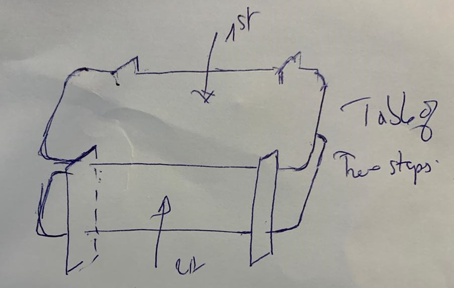
Next, I conceptualized a two-tier table designed to be assembled without additional fasteners or adhesives. I started with hand-drawn sketches to visualize the table's structure and design. Once satisfied with the initial concept, I created a detailed model in SolidWorks. This digital design phase allowed me to refine the dimensions and assembly mechanisms, ensuring the table's stability and functionality before proceeding to the actual machining process.
For the Fab Academy assessment documentation, during the week focused on COMPUTER-CONTROLLED MACHINING, I conceptualized a two-tier table that can be assembled without additional fasteners or adhesives. I began by sketching the initial design to visualize the table's structure and aesthetics. Following the sketching phase, I transitioned to creating a detailed design in SolidWorks. This approach allowed me to refine the dimensions and assembly mechanisms, ensuring the table's stability and functionality before proceeding to the machining stage.
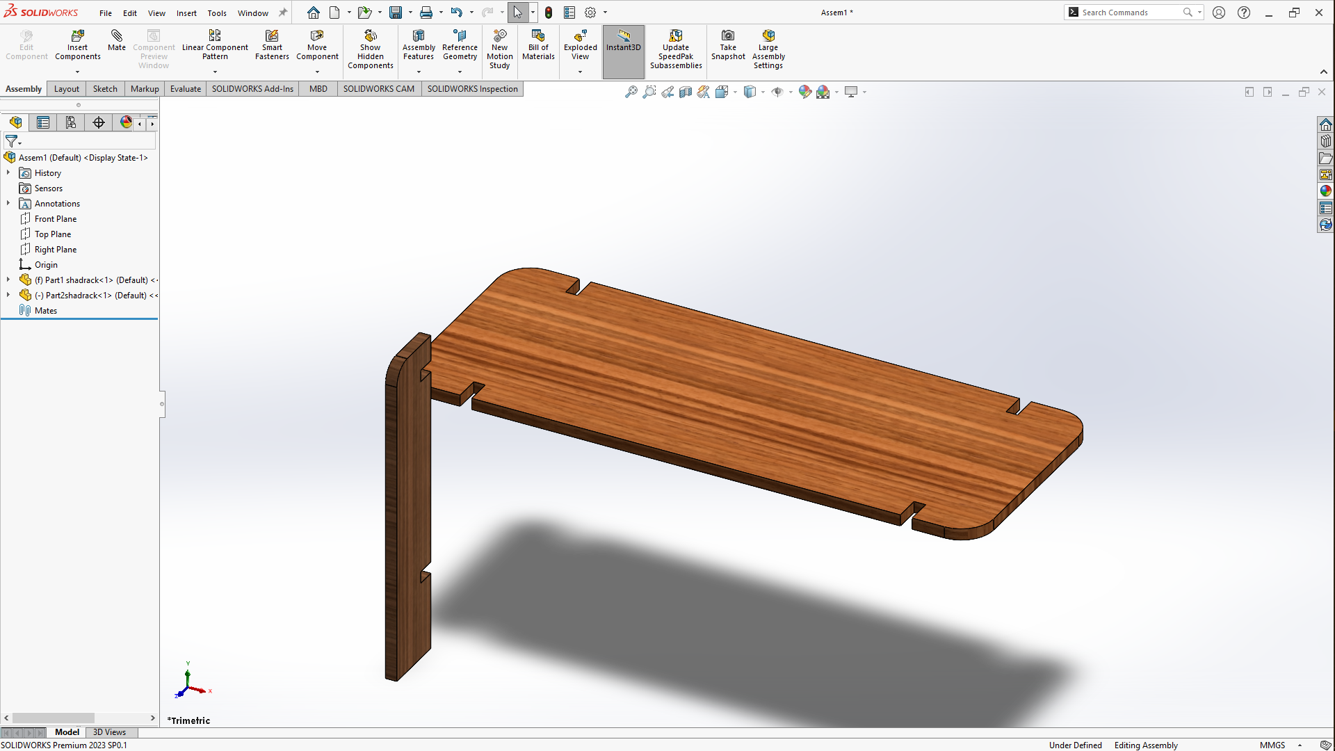
This week's assignment was centered around making something big so i made a small open small open cabinet/shelf.
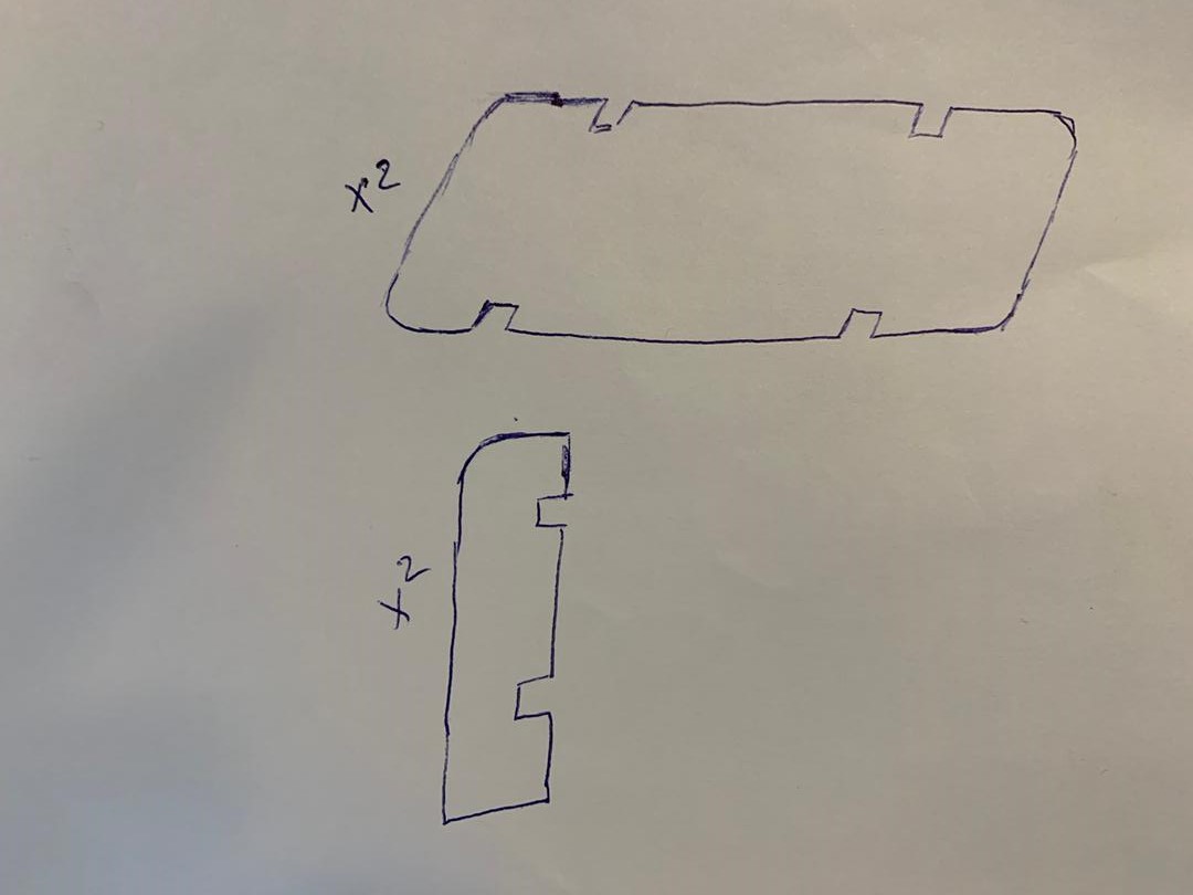
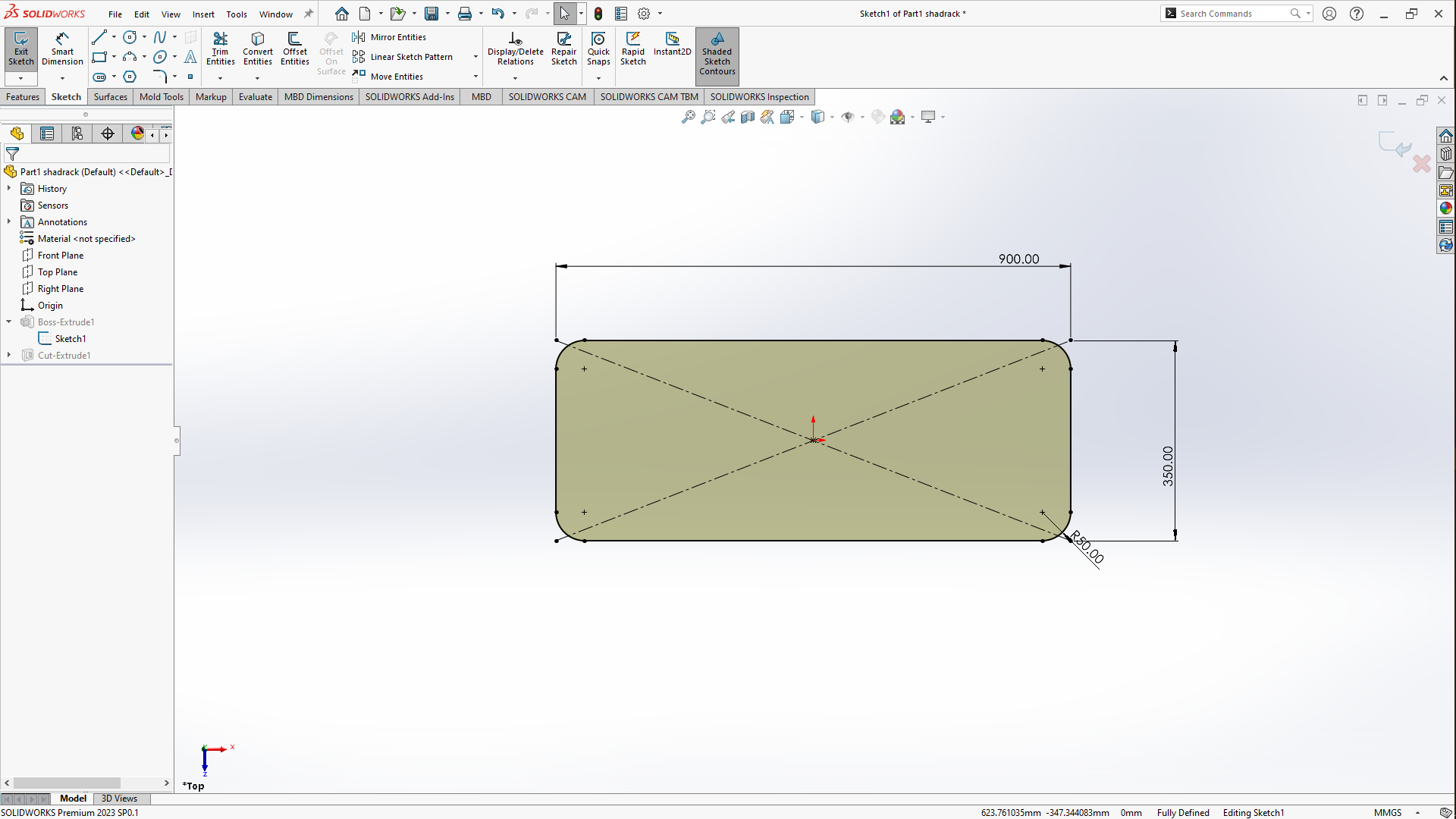
I started the design using the 3CAD software SOLIDWORKS because i'm also familiar with the software due to using it beforehand on multiple occasions. The model is made up of two parts that had to be designed one for the flat parts
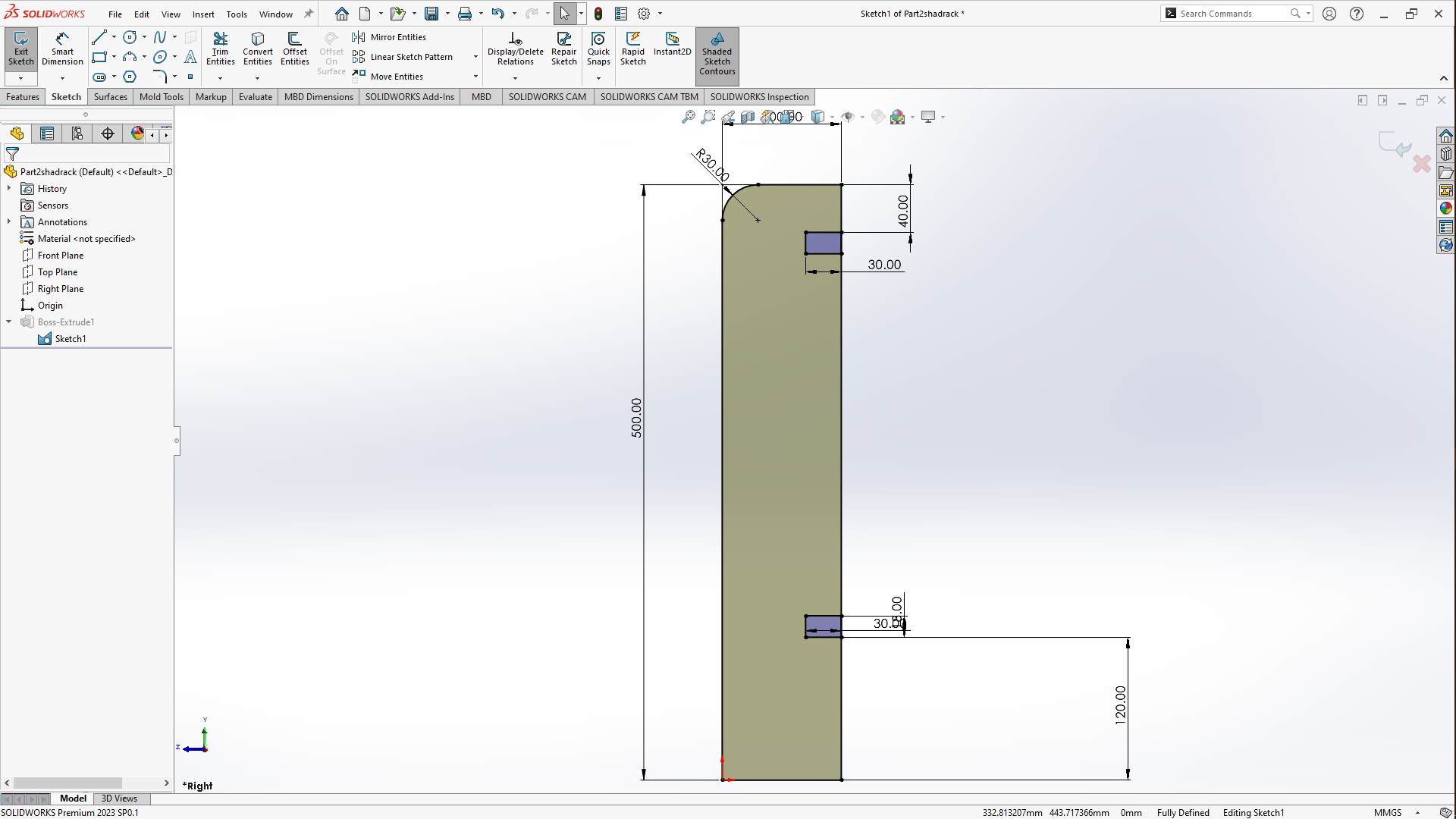
Another sketch for the vertical parts.
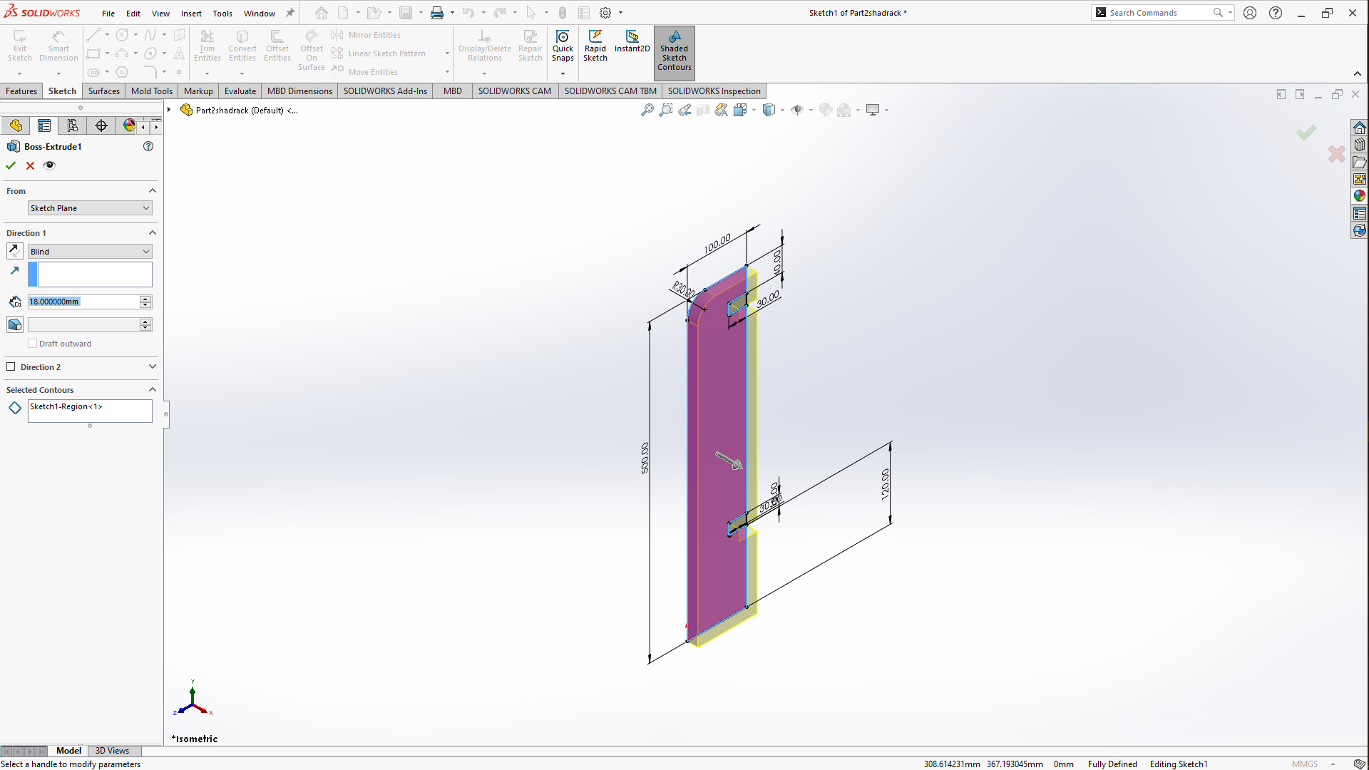
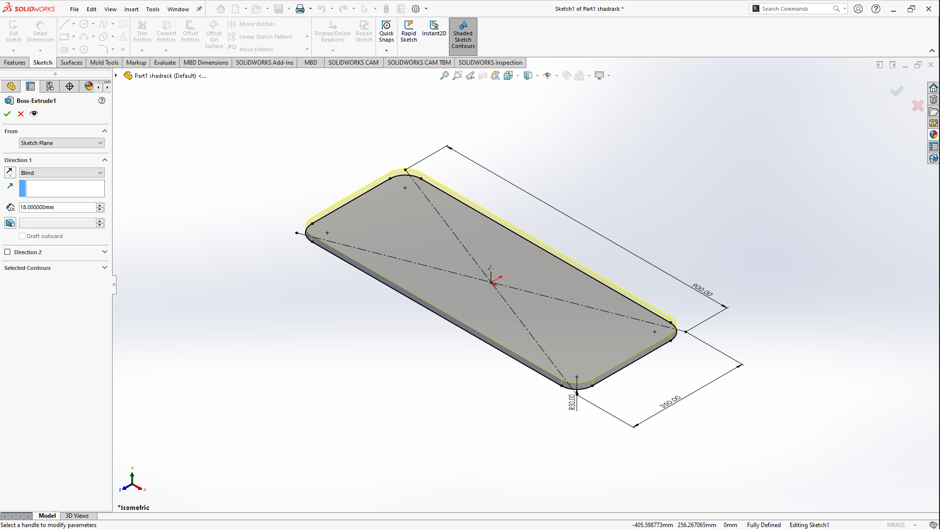
After sketching I extruded the sketch to the thickness of the material, i used the 18MM thickness MDF and after i saved in order to be accessible in the assembly side of the model under part 1 shadrack while the other part was saved under part 2 shadrack, to the right side of the workspace
- Extruding vertical parts
- Extruding flat parts
Assembly
After extruding both parts you save each part, then moved on to assemble the desired small open cabinet/shelf. After assembling, go to NEW you click on its drop down menu, scrolled down to Make Assembly from part/Assemblythen it opens the features that can be seen below in the picture. So at first it opened with the flat part i just finished extruding. The features to inserting componnents can be found above in the commands manager then insert components then a panel opens on the left side, you click on browse to search for the files to be assembled. after its selected you move the curser to the workspace and click to deposit the side and then selected the other part, moved the cursor to the workspace to click and drop the other part.
After putting them in the workspace, i opened mate feature under Assembly in the commands manager.
To assemble parts, I used vertex, so after you have selected both vertex, a menu pop up requesting to choose, between Coincindent, Parallel , Perpendicular , Tangent , Concentric so i chose coincindent, i used vertexes as it only uses one step to mate and for mates. I used the Standard due to the fact it wasn't a more sophisticated mate.
- Mating
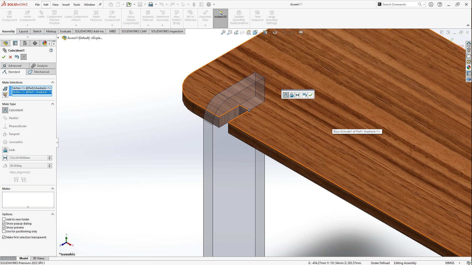
- Final mate
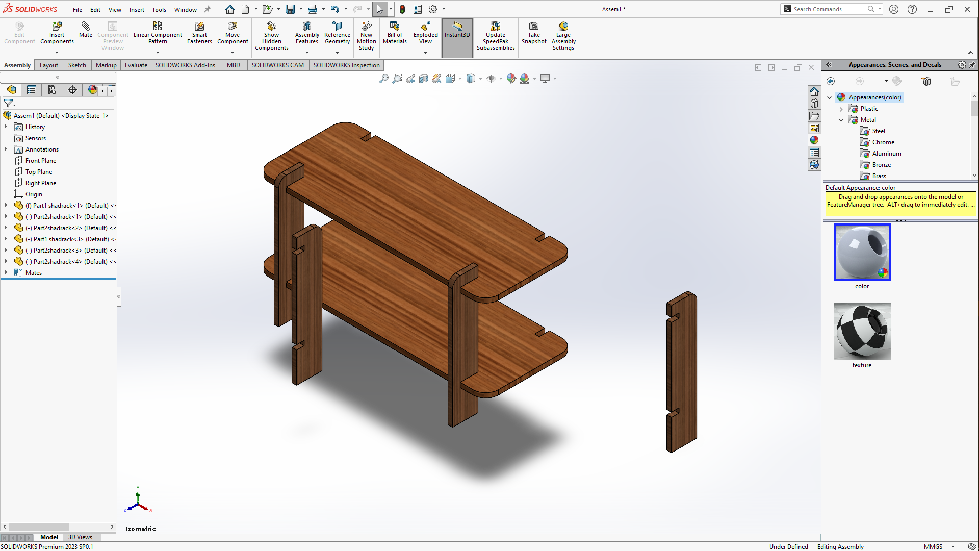
So after adding the two remaining vertical sides i firstly rotated them, by clicking on the assembly in the commands manager then click
on the drop down under move component click on the rotate component then on the leftside click on free drag then select
by delta XYZ then rotated the other legs's Y axis to 60 degrees and then click apply then click ok. Then mated them to the others using
vertexes like i did it before
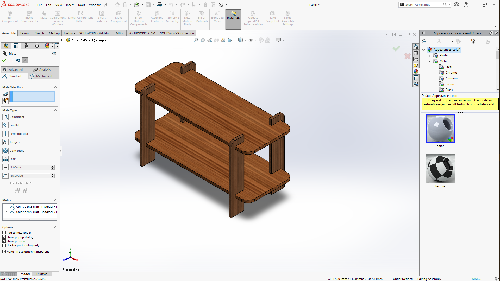
The Final model
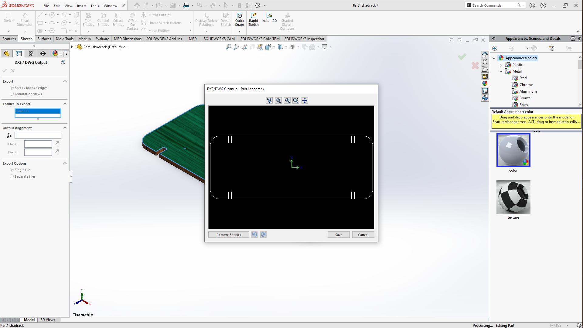
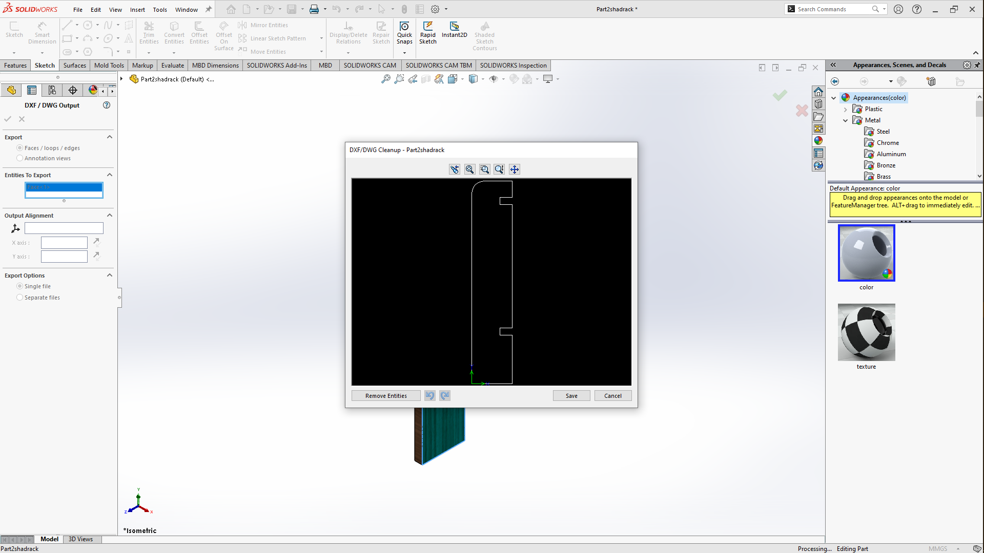
After Saving the files, I also saved the parts as DXF type file but in a way that we save one face of the model as vector file, here's how i did it you go to save the file as usual then save it as DXF type file, it brings you back to solidworks then there's a panel that opens up titled DXF:DWG Output on the left side of the workspace, then select Faces/loops/edges click on the face of the model you want saved as a vector file then preview window opens up to show what would be saved as a vector file then click on SAVE then the file will be saved as vectorized DXF file.
- How i saved flat parts dxf file
- How i saved vertical dxf file
Machinining
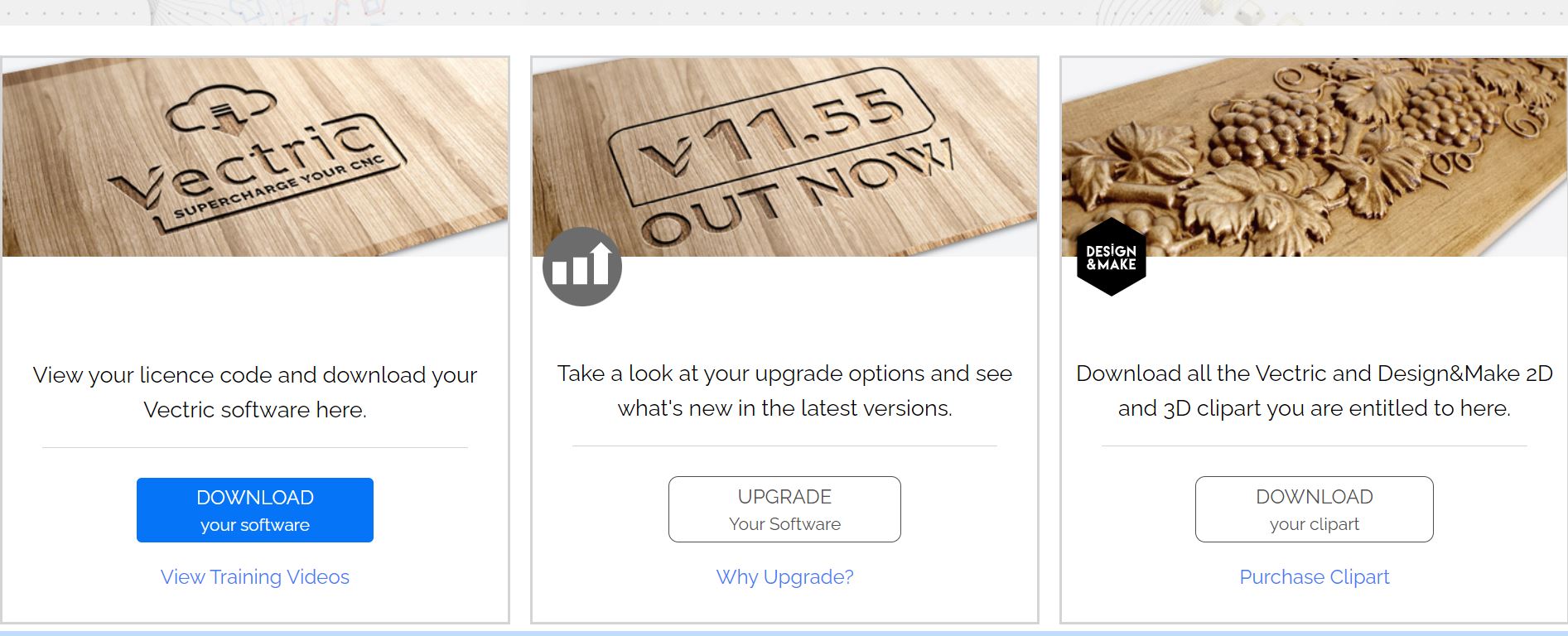
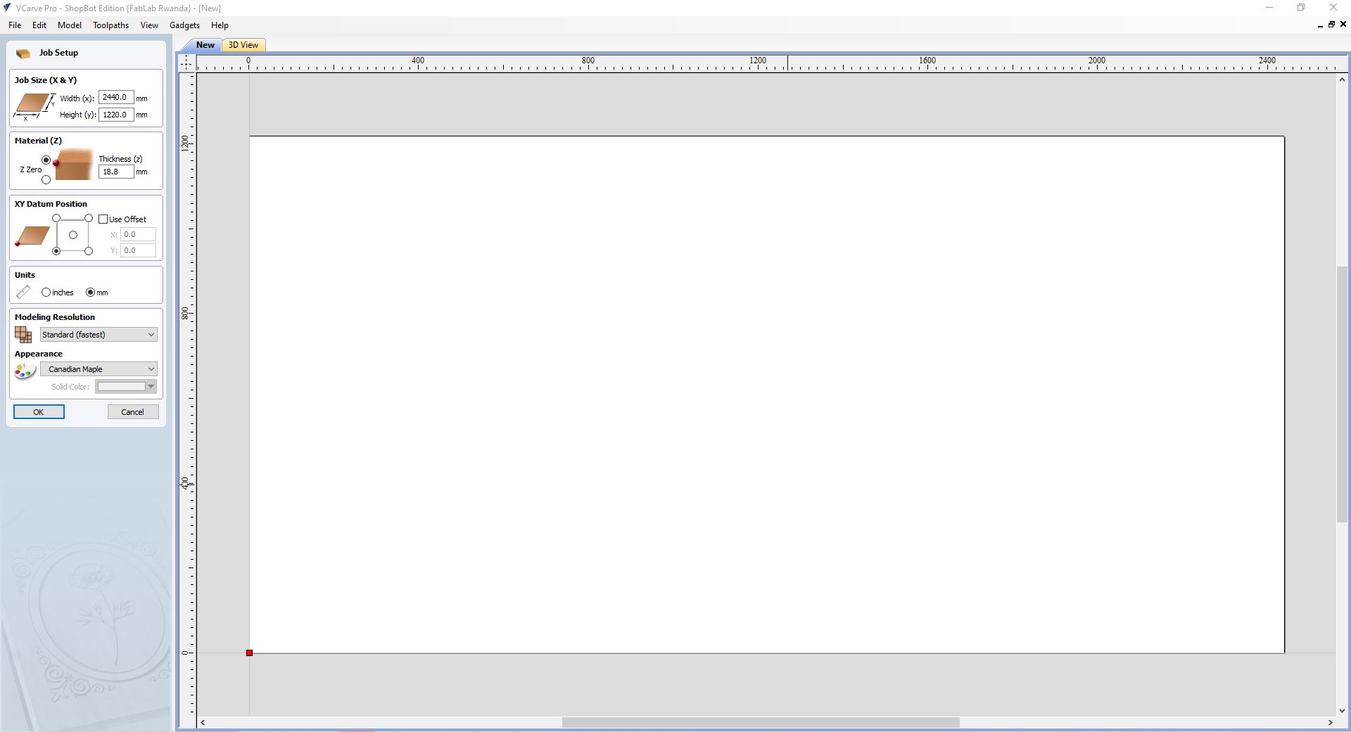
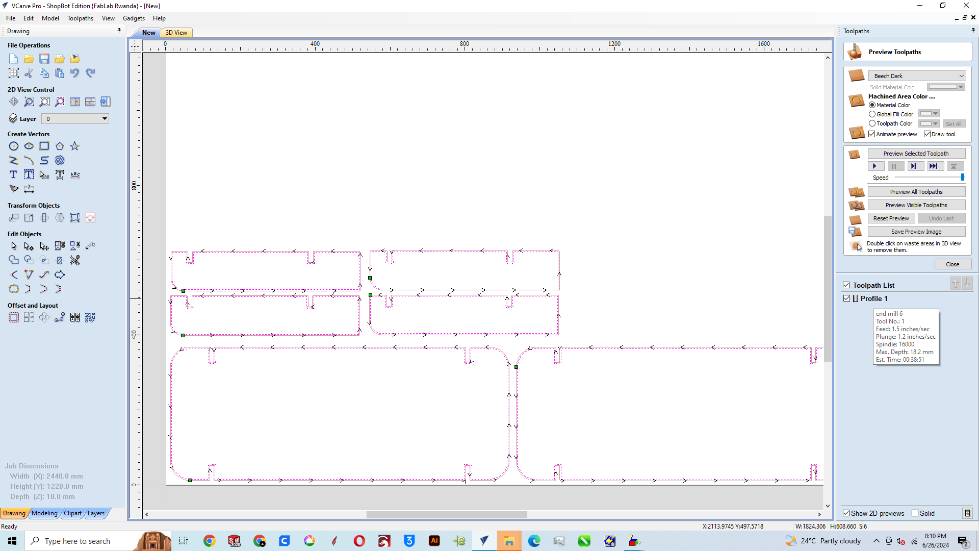
For the machining part i used the DXF files saved from the solidworks model in the Vcarve software. The Vcarve is a software for creating and cutting parts on a CNC Router and our CNC router is shopbot for which further info can be found here, so first you set up the size of the workspace/sheet size, the type of material and it's thickness 18MM and the surface at which the tool will start cutting or the top layer of the sheet/at Z axis 0, next is the working Unit these are the basics of my job set up, but there are other settings for material type, design scale but i wasn't going to use it which is why i left it
I imported the DXF files to the vcarve then selected all the vectors, to multiply it you can either Hold control drag the mouse and then release it Or copy and paste to the side after that i aligned the vectors to the workspace using a feature in the commands manager under Transforming Objects there's a feature named move selected this helped me to align the vectors perfectly to the workspace by leaving a clearance gap of 15MM to the X axis and 15MM to the Y axis for clamps to hold down the sheet tot the machine bed
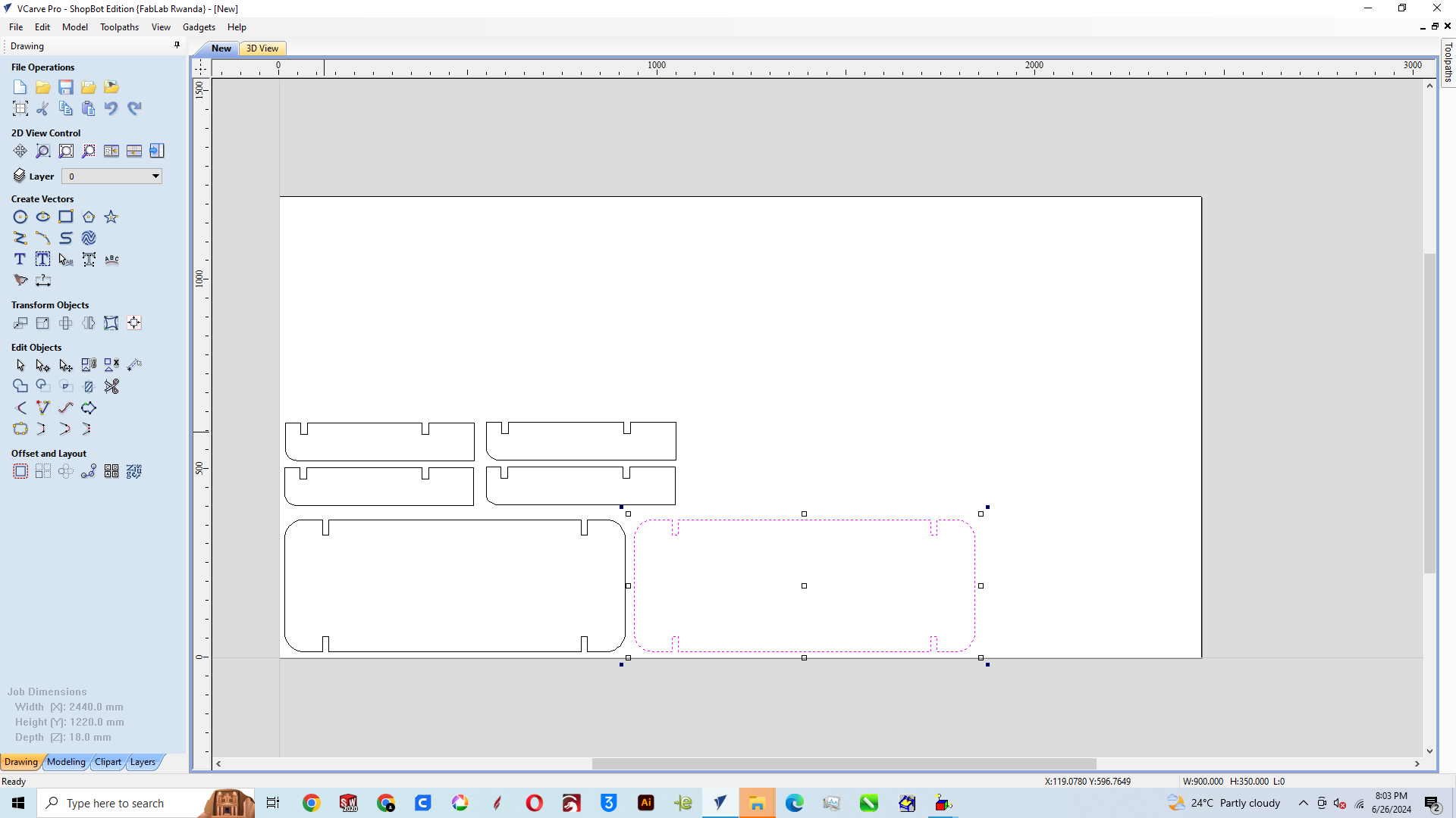
Due to some of the vectors not being fully closed, this is at times due to vectors produced or being generated by another software in this case solidworks, there's a feature in the drawing panel of Vcarve under Edit objects the second icon on the fourth line is for joining open vectors so i selected everything then clicked on join open vectors, with it's opened window i set the tolerance gap to be 0.1MM then clicked on join, then close to apply the feature. As you can see there was 6 open vectors that closed
We add Dog bone a feature under fillet, and fillet is located under edit objects, i set the tool/fillet radius to 3MM, this is done due tot the endmill tool being round so the corners are also going to be round so if we add the pieces together it's not gonna fit to the end due to inside round corners so we add dog bone for tool to go inside past corners round so that when we fit the parts together it holds perfectly
.png)
Cutting Parameters
For cutting parameters in the toolpaths panel i clicked on the 2D profile toolpath, set the start depth to O MM and the cut depth to 18.2MM usually it supposed to be the same thickness as the MDF material but we add the 0.2 MM in order for the tool to go past the MDF sheet help cut out the pieces completely. the tool Diameter is 6MM, the stepover i set it to 65%, this is means that in between the lines of the toolpath, the distance will be 65% of 6MM, the speed of the spindle to be 18000rpm, the feed(the speed at which the tool travel horizontally) set to 1.8INCHES/SEC, the plunge rate speed at which the tool travels vertically; meaning how fast it pierces the sheet of material, i set it to 1.2 INCHES/SEC, clicked apply and close, passes set to 3 due to the fact, a single pass shouldn't plunge to a height beyond the diameter of the tool meaning 6MM so i set three passes, for machine vectors i choose Outside due to the fact that i wanted the cutout pieces and then i clicked on calculate to see the time it would take to machine this which was about 1 hour 25min
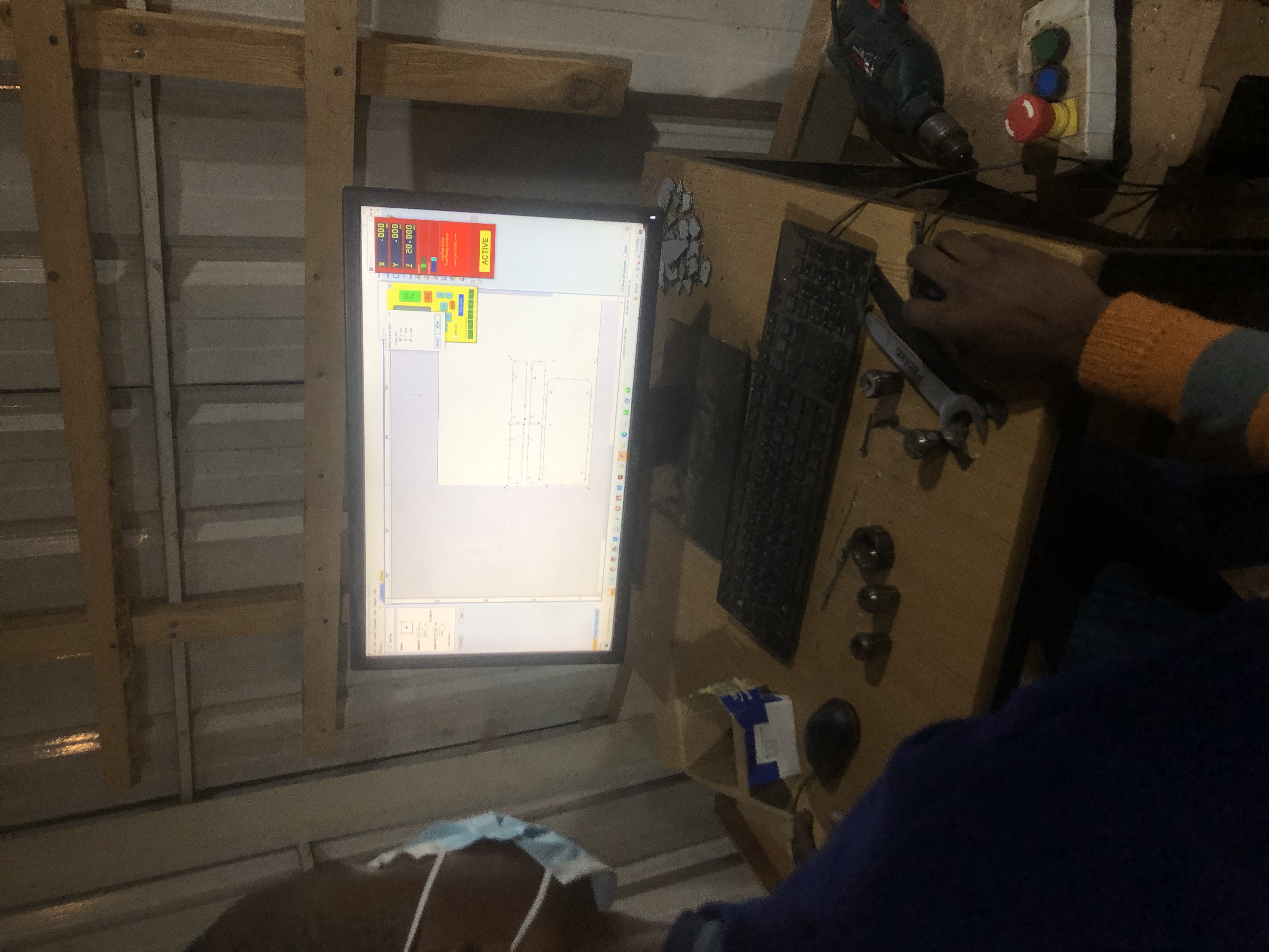
Setting axis
So after you have saved the file, it automatically opens up the shopbot controller and using the controller to set the origin. I turned the CNC router switch on, locked the machine to the computer with the reset button(the blue button on the pushbutton) in order to be able to drive the gantry using the controller handles. After, i moved to positioning the tool at the origin of the sheet material as precise as possible, to set XYZ or the beginning of the machining
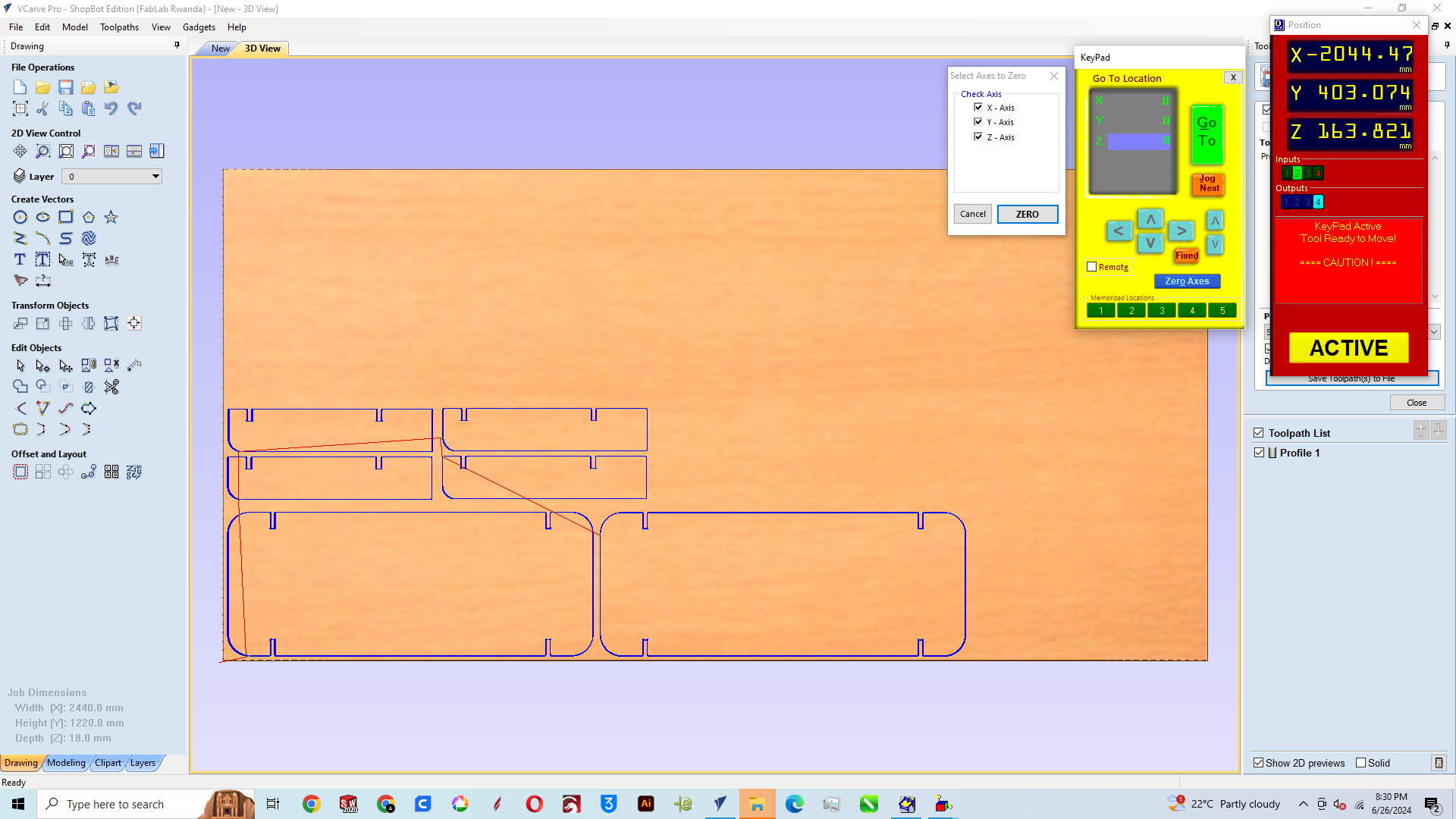
Setting zero axis on the controller on the controller panel, there is a small yellow keypad, i clicked on it opened another panel now you click on the zero axis then it opens another panel for selecting the axis i'm going to set at zero hence the origin of the work so i selected all 3 axis; XYZ then clicked on Zero then i closed the yellowpad
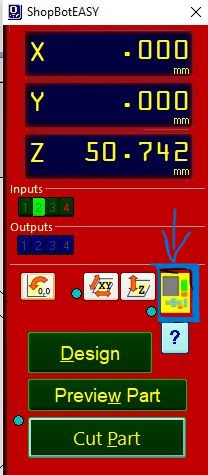
After setting XYZ i moved to start machining so i clicked on Cut part then it opened where i had saved my file before then i clicked on Open
After clicking on open before you go on with starting the work you must turn on the spindle first to avoid tool damage, i pushed the start button (the green button on the push button) on the pushbutton box to start the machine spindle and then with the window that opened on the screen i clicked enter on the keyboard and the machining started
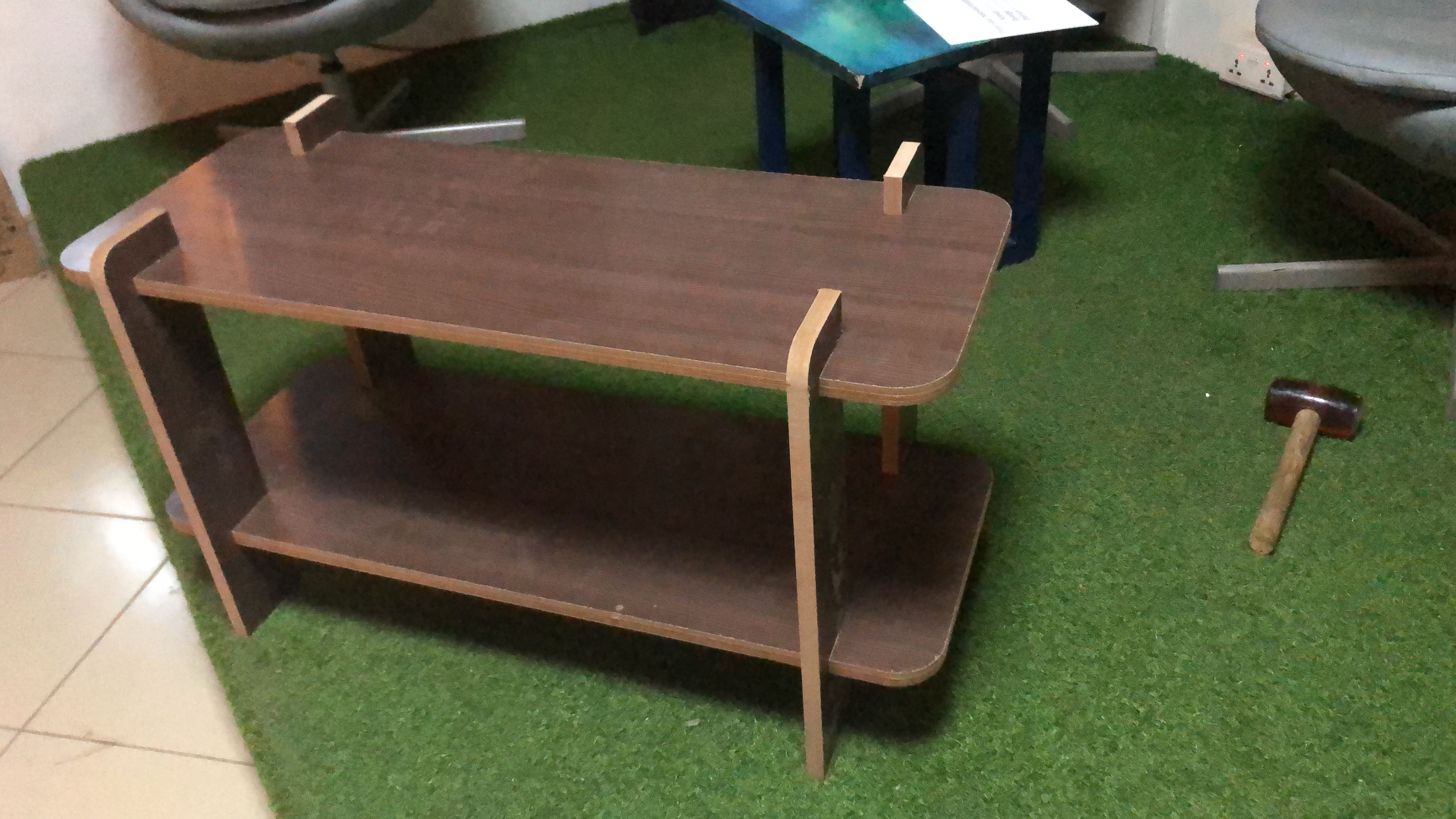
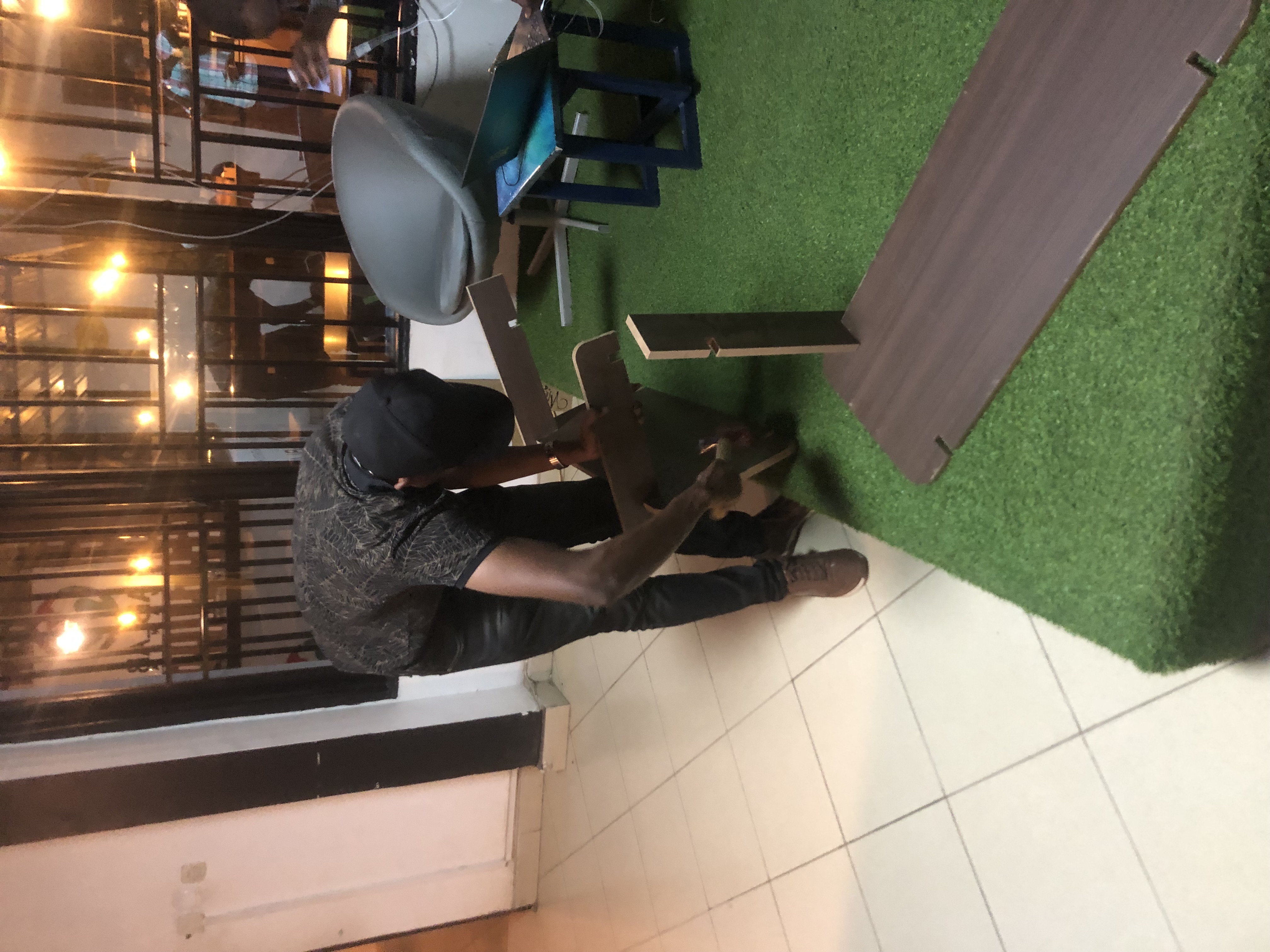
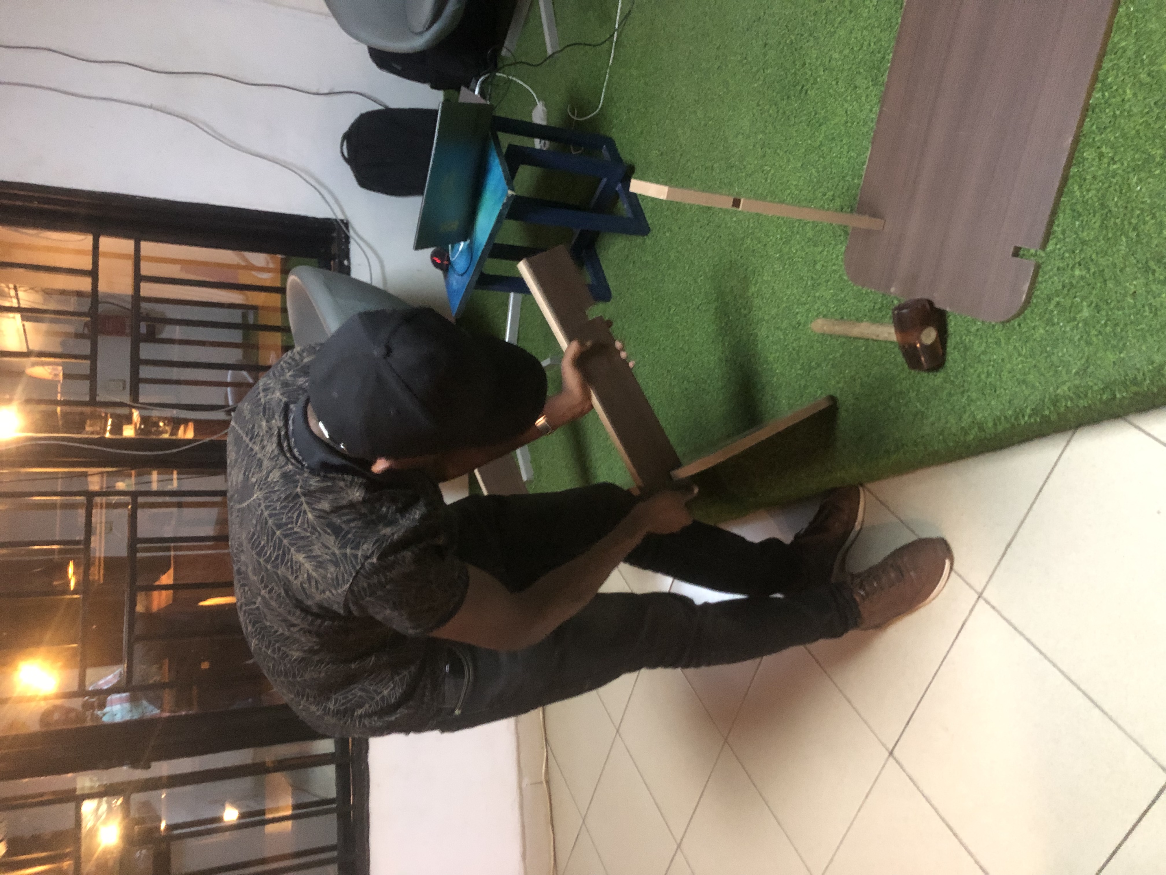
After Machining, i assembled the parts to make the small open cabinet/shelf uisng the mallet to punch together the parts that hardly fit together.
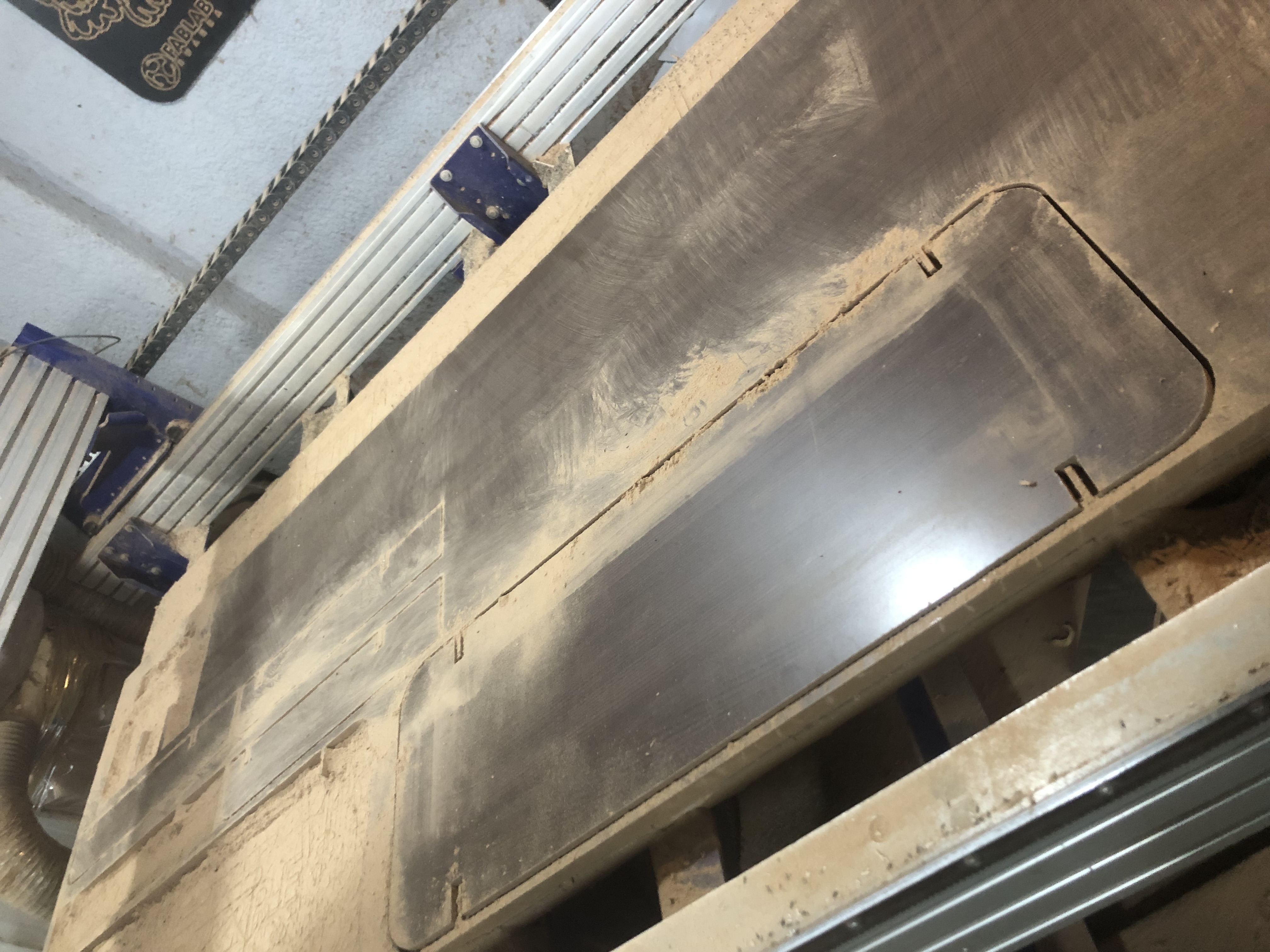
After taking the material off the CNC i started assembling the model
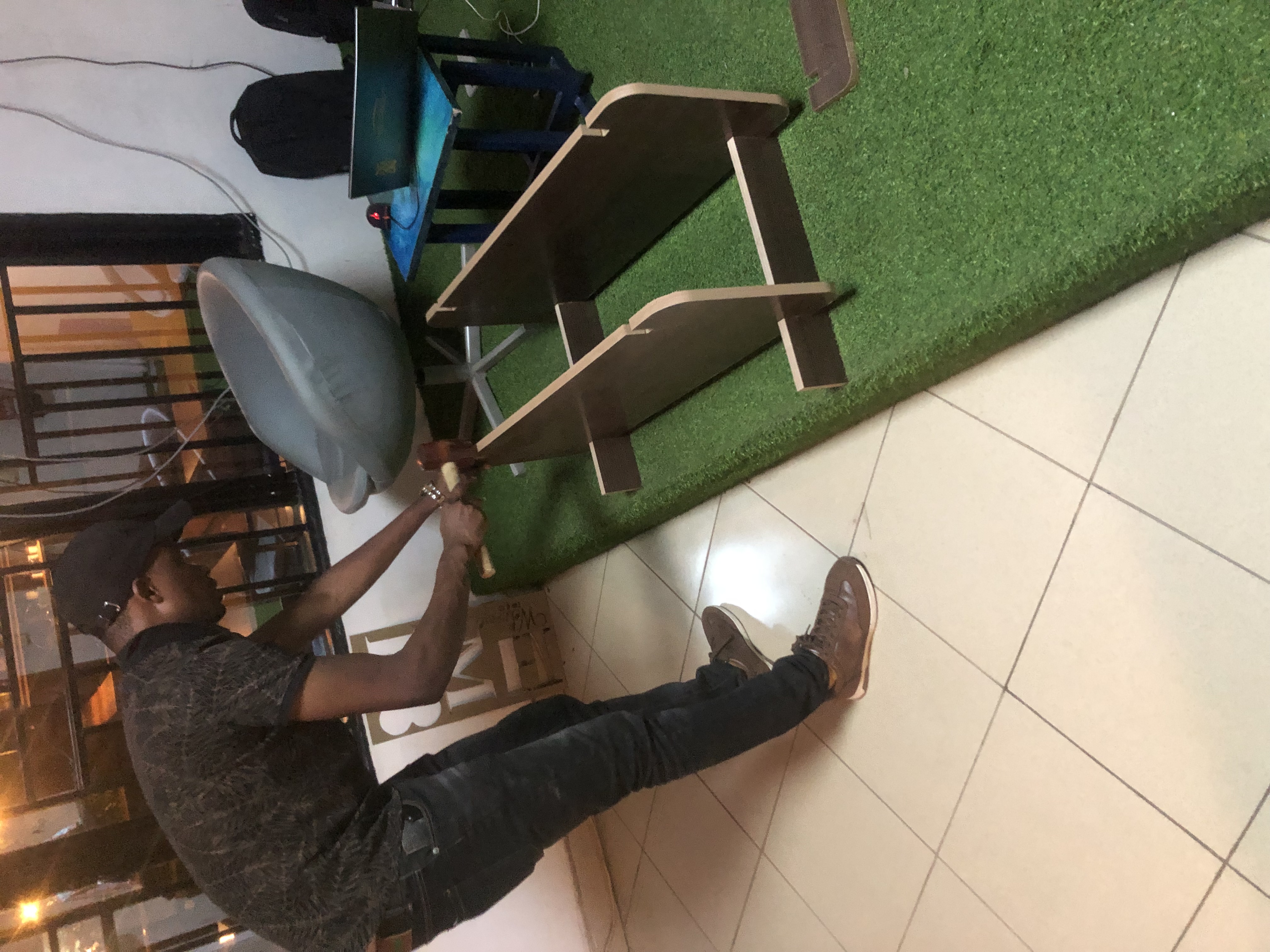
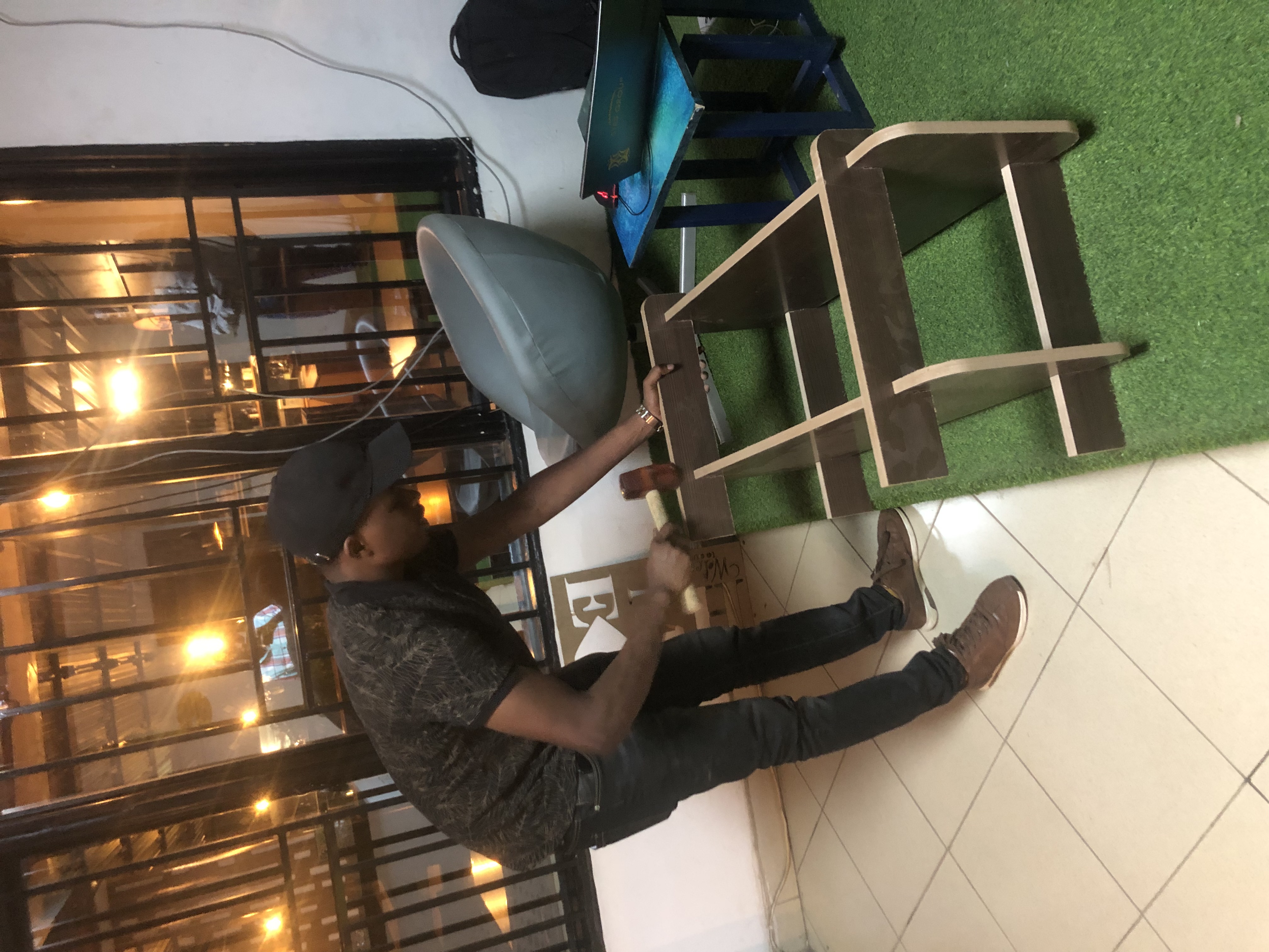
the shelf