Browse through the datasheet for your microcontroller
Compare the performance and development workflows for other architectures
Document your work to the group work page and reflect on your individual page what you learned
Individual assignment:
Write a program for a microcontroller development board to
interact (with local input &/or output devices)
and communicate (with remote wired or wireless devices)
Group Assignment
The group assigment link is available here on the fabalab page.
What is Embedded programming?
Embedded programming is the process of writing code for embedded systems, which are specialized computing devices designed to perform specific functions within larger systems or products. These systems typically have limited processing power, memory, and resources compared to general-purpose computers.
Embedded programming involves writing software that controls the behavior of the embedded system, interacts with hardware components such as sensors and actuators, and performs specific tasks or functions. It often requires a deep understanding of the hardware architecture and the ability to optimize code for efficiency and resource constraints.
Embedded programming is used in various industries and applications, including automotive, aerospace, consumer electronics, medical devices, industrial automation, and IoT (Internet of Things) devices. It plays a crucial role in enabling the functionality of devices ranging from simple microcontrollers to complex embedded systems with real-time operating systems.
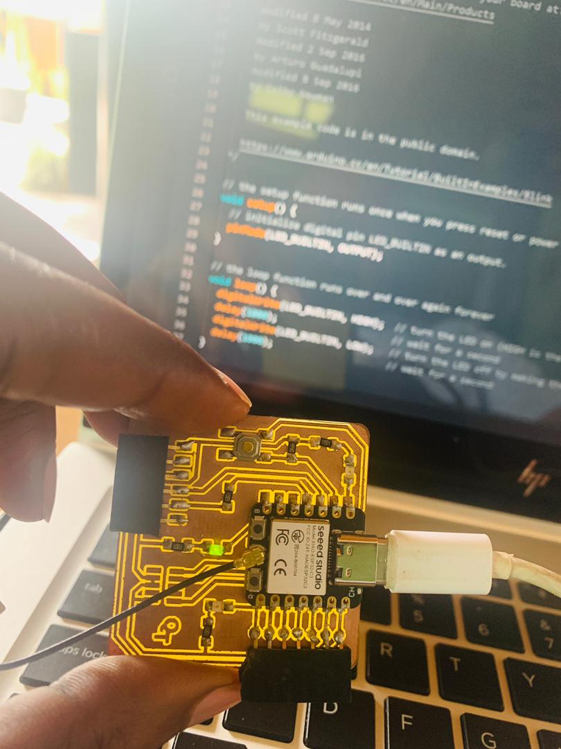
This week, I'm utilizing the board we manufactured during week 4. I've been engaging with the LEDs and push buttons on it.
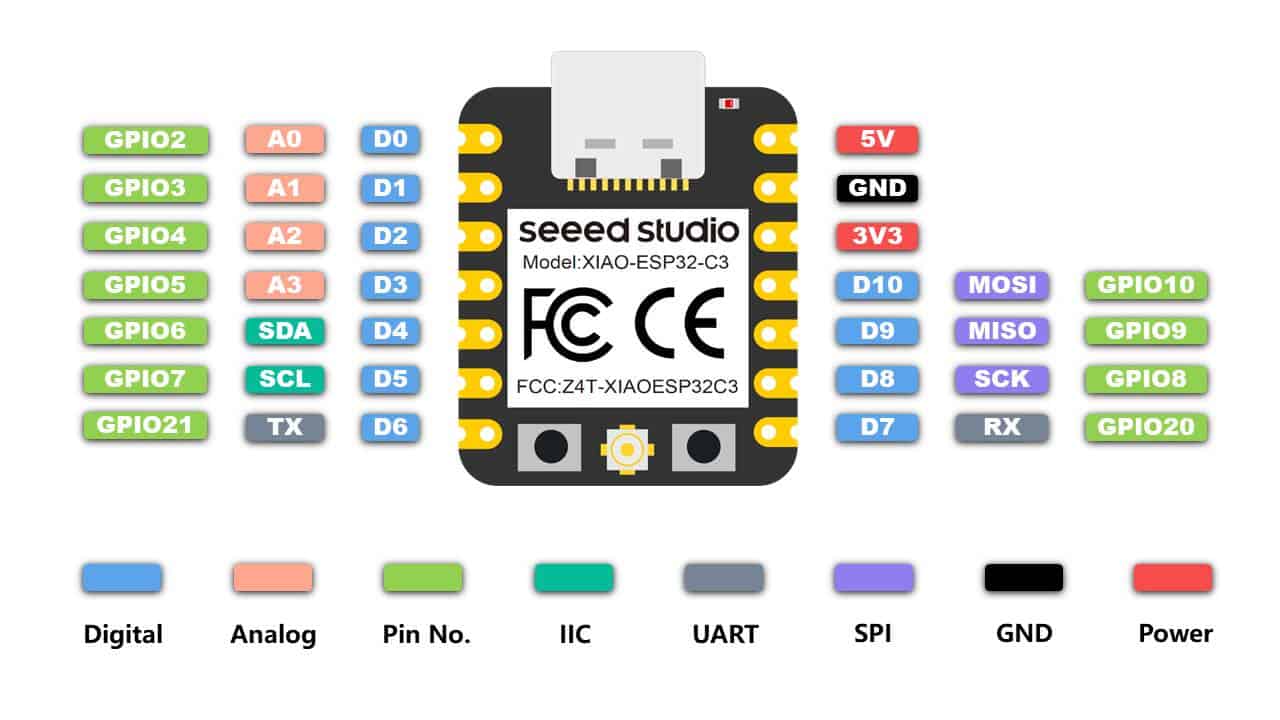
I employed the ESP32C3 microcontroller from Seeed Studio, a Chinese company, as the primary component to control the blinking of the LEDs.
LEDs Blink code
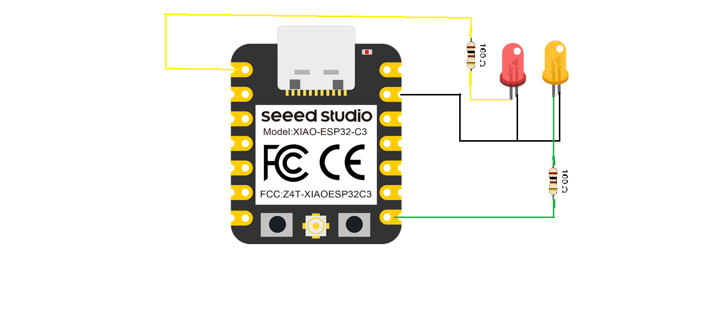
Wiring Connection
Output
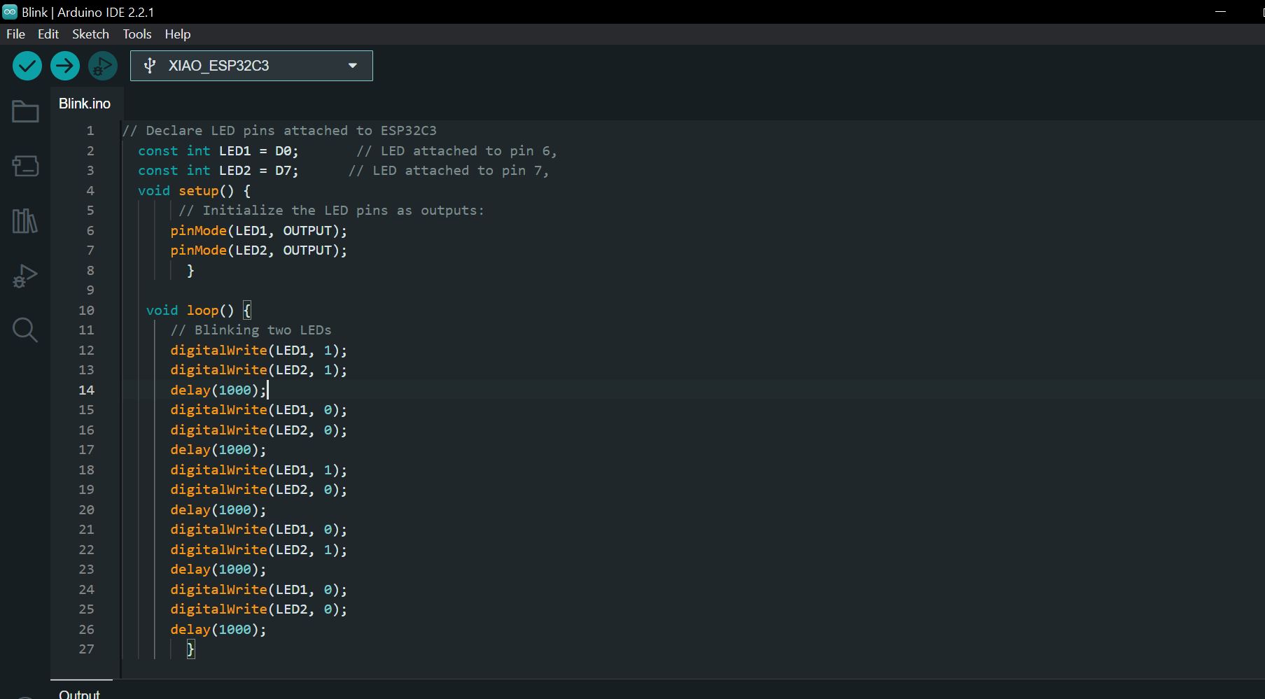
Blink Code
                    // Declare LED pins attached to ESP32C3
  const int LED1 = D0;       // LED attached to pin 6,
  const int LED2 = D7;      // LED attached to pin 7,
  void setup() {
       // Initialize the LED pins as outputs:
      pinMode(LED1, OUTPUT);
      pinMode(LED2, OUTPUT);
        }

   void loop() {
      // Blinking two LEDs
      digitalWrite(LED1, 1);
      digitalWrite(LED2, 1);
      delay(1000);
      digitalWrite(LED1, 0);
      digitalWrite(LED2, 0);
      delay(1000);
      digitalWrite(LED1, 1);
      digitalWrite(LED2, 0);
      delay(1000);
      digitalWrite(LED1, 0);
      digitalWrite(LED2, 1);
      delay(1000);
      digitalWrite(LED1, 0);
      digitalWrite(LED2, 0);
      delay(1000);
        }
Fading LEDs
Fading LEDs refers to a technique where the brightness of light-emitting diodes (LEDs) is
gradually increased or decreased in a smooth and controlled manner. This effect creates a
visually pleasing transition between different light intensities, rather than a sudden on/off effect.
In electronics and programming, fading LEDs are often achieved using pulse
width modulation (PWM). PWM involves rapidly switching the LED on and off at varying duty cycles.
By adjusting the duty cycle (the ratio of on-time to off-time),
I can control the average power delivered to the LED, which in turn controls its brightness.
Fading LEDs can be used for various purposes, such as creating ambient lighting effects,
simulating natural light changes, or adding visual appeal to
projects like mood lamps, decorative displays, or artistic installations.
LEDs Wiring
I opted to use the LED connected to Pin D1 on my board for feeding LED functionality.
You can find details on the wiring in the "blink" wiring section above. Additionally,
ensure you have correctly connected the LED to Pin D1 for proper functionality.
Code
int led = D0;         // the PWM pin the LED is attached to
int brightness = 0;  // how bright the LED is
int fadeAmount = 5;  // how many points to fade the LED by
void setup() {
  pinMode(led, OUTPUT);
}
void loop() {
  analogWrite(led, brightness);
  brightness = brightness + fadeAmount;
  if (brightness <= 0 || brightness >= 255) {
    fadeAmount = -fadeAmount;
  }
  delay(30);
}
Output
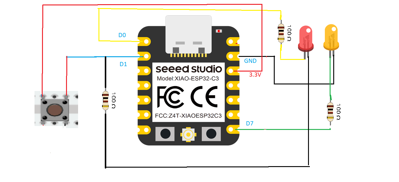
Control LEDs with Push Button
Implement LED control using a push button switch.
This project involves programming a
microcontroller to respond to button presses by toggling the state of LEDs connected to it.
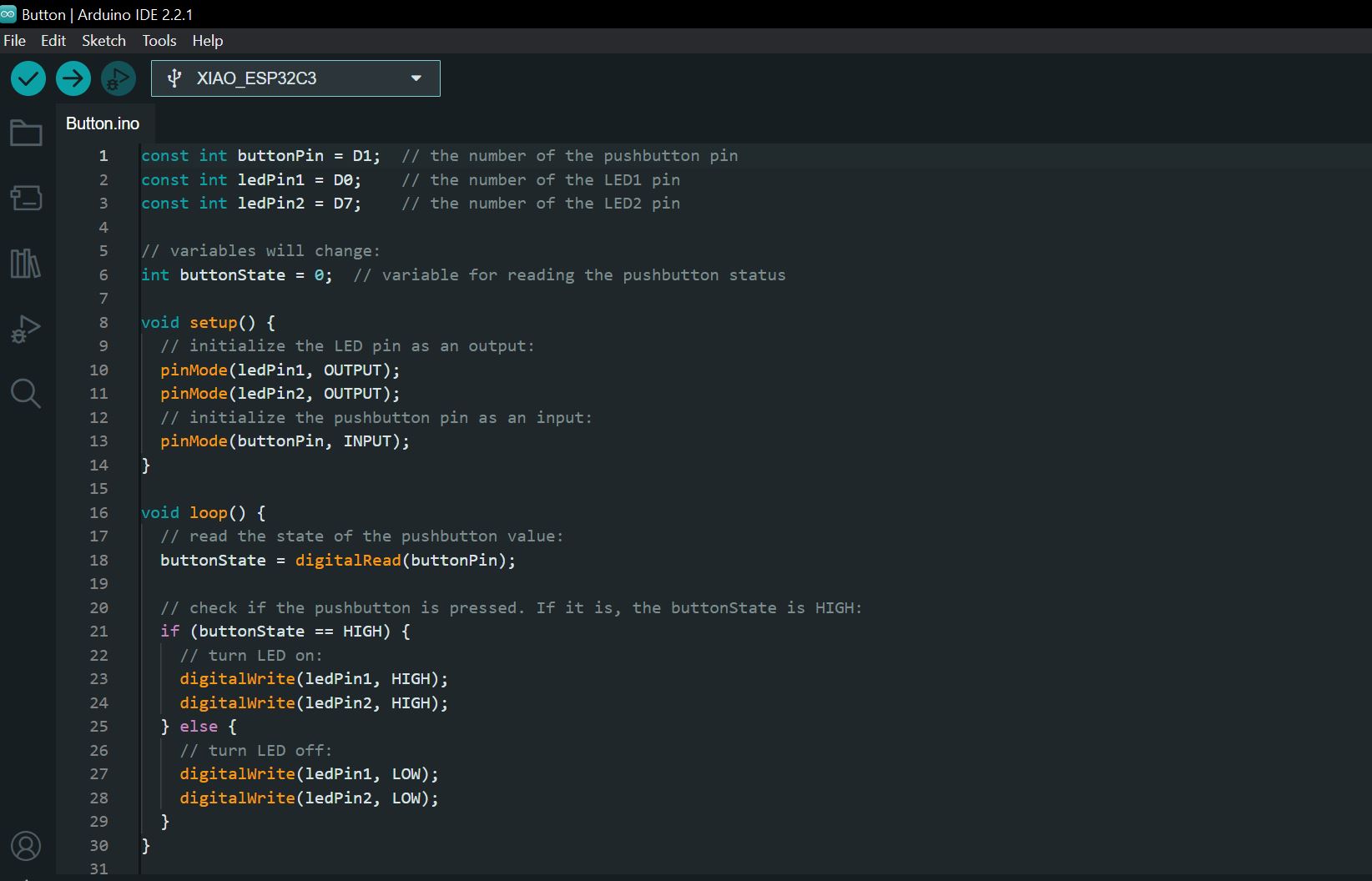
Wiring
Code
const int buttonPin = D1;  // the number of the pushbutton pin
const int ledPin1 = D0;    // the number of the LED1 pin
const int ledPin2 = D7;    // the number of the LED2 pin

// variables will change:
int buttonState = 0;  // variable for reading the pushbutton status

void setup() {
  // initialize the LED pin as an output:
  pinMode(ledPin1, OUTPUT);
  pinMode(ledPin2, OUTPUT);
  // initialize the pushbutton pin as an input:
  pinMode(buttonPin, INPUT);
}

void loop() {
  // read the state of the pushbutton value:
  buttonState = digitalRead(buttonPin);

  // check if the pushbutton is pressed. If it is, the buttonState is HIGH:
  if (buttonState == HIGH) {
    // turn LED on:
    digitalWrite(ledPin1, HIGH);
    digitalWrite(ledPin2, HIGH);
  } else {
    // turn LED off:
    digitalWrite(ledPin1, LOW);
    digitalWrite(ledPin2, LOW);
  }
}