Interface and Application Programming
This weeks task was:
Group assignment:
Compare as many tool options as possible.
Document your work on the group work page and reflect on your individual page what you learned.
Individual assignment
Write an application that interfaces a user with an input and/or output device(s) on a board that you made.
Group Work
Our group work was done on Siddart's Page
Learnings from group work
During our group work this week, I learned about the unique features and applications of Processing, P5.js, and Blynk. Processing, a Java-based tool, is excellent for creating visual art and interactive graphics, with extensive libraries for graphics, sound, and video. P5.js, a JavaScript library, is ideal for web-based projects, enabling interactive graphics and animations directly in web browsers. Blynk, an IoT platform, allows for remote control and monitoring of hardware devices through simple mobile and web app interfaces, making it easy to develop IoT applications with its user-friendly GUI and drag-and-drop features. These insights will help me choose the right tools for future interactive and IoT projects.
Individual Assignment
What are interfaces?
Interfaces typically refer to the point of interaction between different systems, components, or entities. In computing, an interface is a set of methods or functions that define how different software components can communicate or interact with each other. It establishes a boundary across which different software components can exchange information, pass data, or request services without needing to know the internal workings of each other.
What does API Stand for?
API stands for Application Programming Interface. An API (not to be confused with the American Petroleum Institute), an acronym for Application Programming Interface, is a set of definitions and protocols that allow technology products and services to communicate with each other via the internet of things (IoT).
What is Application Programming Interface (API)?
An API defines a set of rules and protocols that allow different software applications to communicate with each other. APIs enable developers to access the functionality of external services, libraries, or platforms in their own applications.
What are APIs Used For?
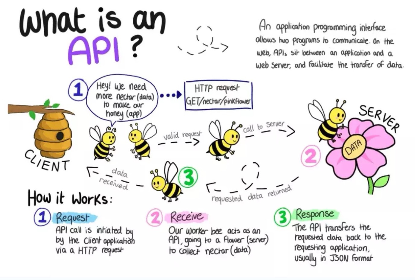
Essentially, an API allows two software programs to communicate with each other. One program can call another program’s API to get access to data or functionality of the other program.
To understand exactly how an API works, consider this non-technical example. When you go to a restaurant, a waiter will take your order and report it to the kitchen. The kitchen makes your food, and the waiter brings it back to your table.
In this example, one program is you (the person ordering food), and one program is the kitchen. The waiter represents the API that is used to receive requests and return something. In this case, the waiter returns your order, but an actual API would return data or other functionality.
What does an API do?
In simplest terms, an API acts as a middleman between two or more applications, accepting messages and returning a response. When developing a complex application, we write all of the data manipulation code on the server, which is not accessible to the user on the client side. It is primarily for security reasons. A server is a separate application that is hosted elsewhere.
To obtain data from the server, we must use the server’s API. The API will return a response to the client based on their authentication level.
An API isn’t just for getting data. It can also be used to create, delete, or exchange data on the server.

Assignment
write an application that interfaces a user with an input &/or output device that we made and also compare as many tool options as possible
Processing using the Xiao RP2040:
Initially I was very confused about this week, so I started with referring at Jesal sir's documentation..
In this assignment, I worked on a project using the Seeed Xiao RP2040 microcontroller and Processing. I created a sketch in Processing that displays a circle on the screen. When I clicked within the circle, the built-in RGB LED on the Xiao RP2040 would light up. This project demonstrated how to interface hardware components with software applications, enabling real-time data visualization and interaction between the microcontroller and the Processing sketch.
I began by examining his code for creating a circle in Processing. The goal was to program the RP2040 so that when you click within the circle, the built-in RGB LED on the Xiao lights up.
Using this concept, I experimented by changing the shape of the sketch and altering the colors based on mouse clicks.
Logic behind my code
The Arduino code listens for serial data representing red and green color values. When it receives these values, it updates the color of an RGB LED connected to the Seeed Xiao RP2040. The Processing code creates a graphical interface with a square representing the LED. Clicking the left or right mouse button within the interface sends commands over the serial port to turn the LED on or off. Dragging the mouse or pressing any key sends additional commands to change the LED's state. The outcome is a synchronized visual and hardware interaction where actions in the Processing interface control the LED's color and state on the Xiao RP2040.
Steps of setup
Step 01: Softwares
For Processing you need to have processing IDE for creating the visualization sketch
and Arduino IDE for programming the Seeed Xiao RP2040
Step 02: Connect
Connect rp2040 board to your computer and upload rp2040 code on arduino IDE
    #include
      #define numpixels 1
      #define pixelpower 11
      #define pixelpin 12
      Adafruit_NeoPixel pixel(numpixels, pixelpin, NEO_GRB + NEO_KHZ800);


      void setup() {
        Serial.begin(9600); // Set the baud rate to match the Processing sketch

        pinMode(pixelpower, OUTPUT);
        pixel.begin();
        digitalWrite(pixelpower, HIGH);

      }

      void loop() {
        if (Serial.available())
        {
          char g = Serial.read();
          char r = Serial.read();
          Serial.print(r);
          Serial.print(" ");
          Serial.println(g);

          int r_ = int(r);
          int g_ = int(g);

          pixel.setPixelColor(0, pixel.Color(r_, g_, 128));
          pixel.show();
          delay(200);
          pixel.setPixelColor(0, pixel.Color(0, 0, 0));
          pixel.show();
        }
      }
Open processing IDE and upload processing code
    import processing.serial.*;

Serial myPort;

void setup() {
  size(300, 300); // Set the size of the canvas
  myPort = new Serial(this, "COM6", 9600); // Open the serial port
  myPort.bufferUntil('\n'); // Wait for a newline character
}

void draw() {
  // Draw the canvas
  background(255);
  rectMode(CENTER);
  rect(width / 2, height / 2, 100, 100); // Draw a square representing the LED

  // Check for mouse click
  if (mousePressed && (mouseButton == LEFT)) {
    myPort.write('1'); // Send '1' to turn on the LED
  } else if (mousePressed && (mouseButton == RIGHT)) {
    myPort.write('0'); // Send '0' to turn off the LED
  }
}

void mouseDragged() {
  myPort.write('3');
}

void keyPressed() {
  myPort.write('2');
}
Heroshot
Web Server using Blynk.io
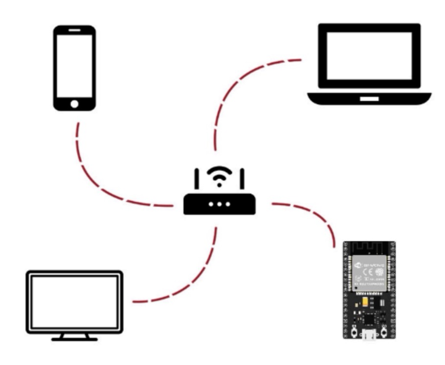
A webserver is a virtual interface to visualize and control your ESP and all of its I/Os.
You can connect to the internet and use your phone / laptop to perform all operations.
Go to blynk.io and sign up. Link for blynk.io
After signing up log in with the same email id and password on the same link.
Download the same app on your phone as well and log in with the same email id and password
Steps
The page will redirect you to the dashboard interface.
1. Go to developer zone > My templates > New Template
2. Select Esp8266 in hardware and connection type as wifi and add the description.
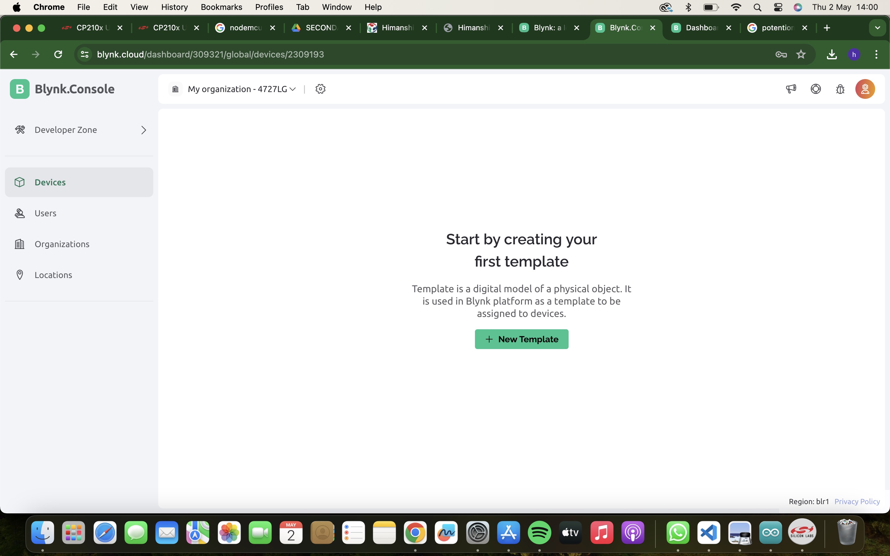
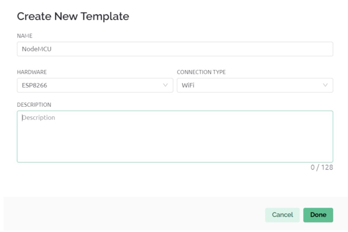
3. You’ll see the following interface.
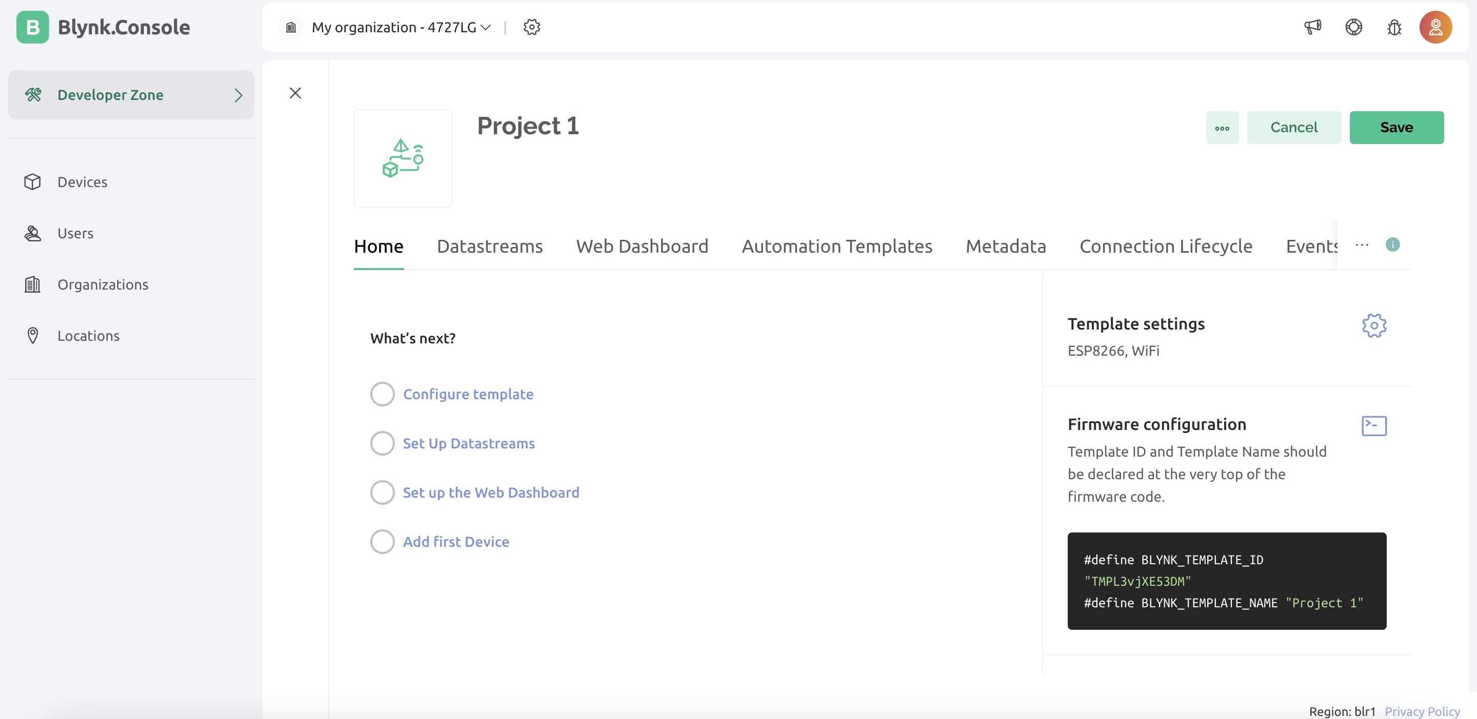
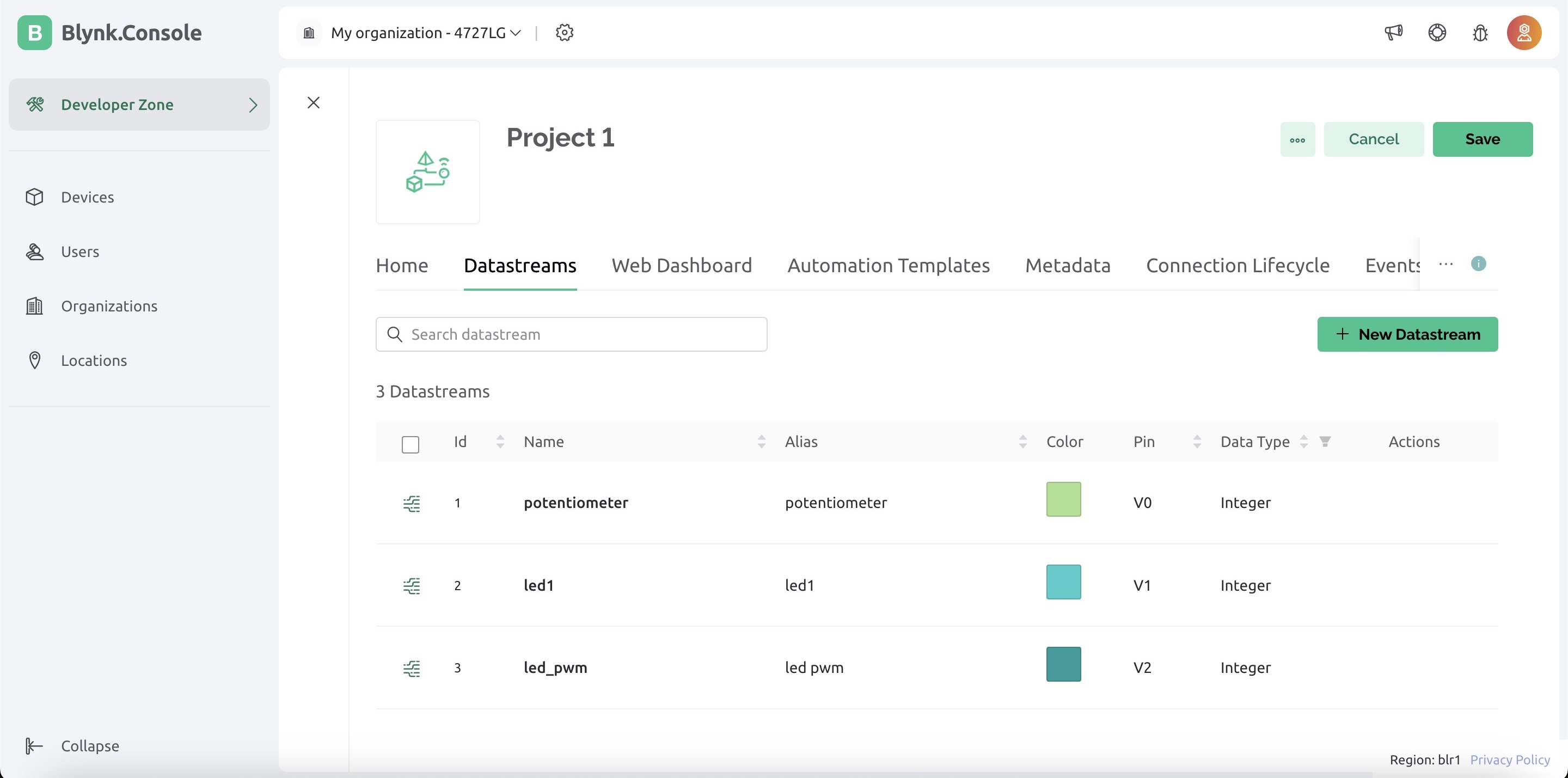
4. Go to Datastreams. Every I/O device will be defined in Datastreams.
Click on edit to add/remove data streams.


5. Go to the Web Dashboard. This is the GUI for visualizing/ controlling through a web browser. Click On edit. Go to the Widget box to add elements.


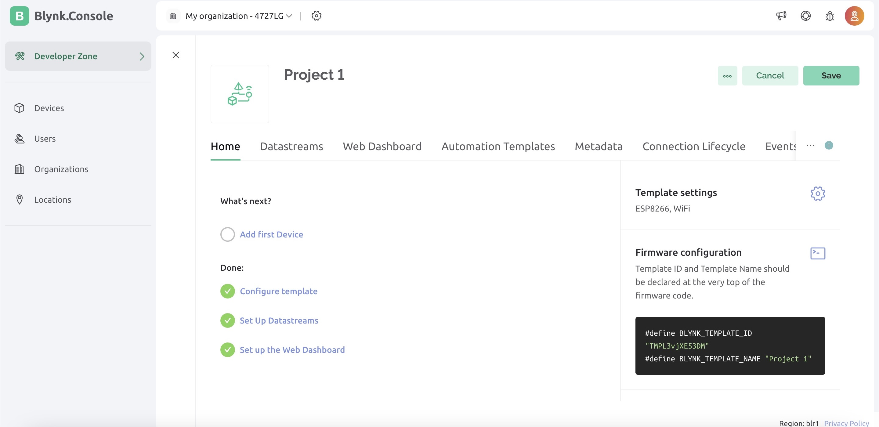
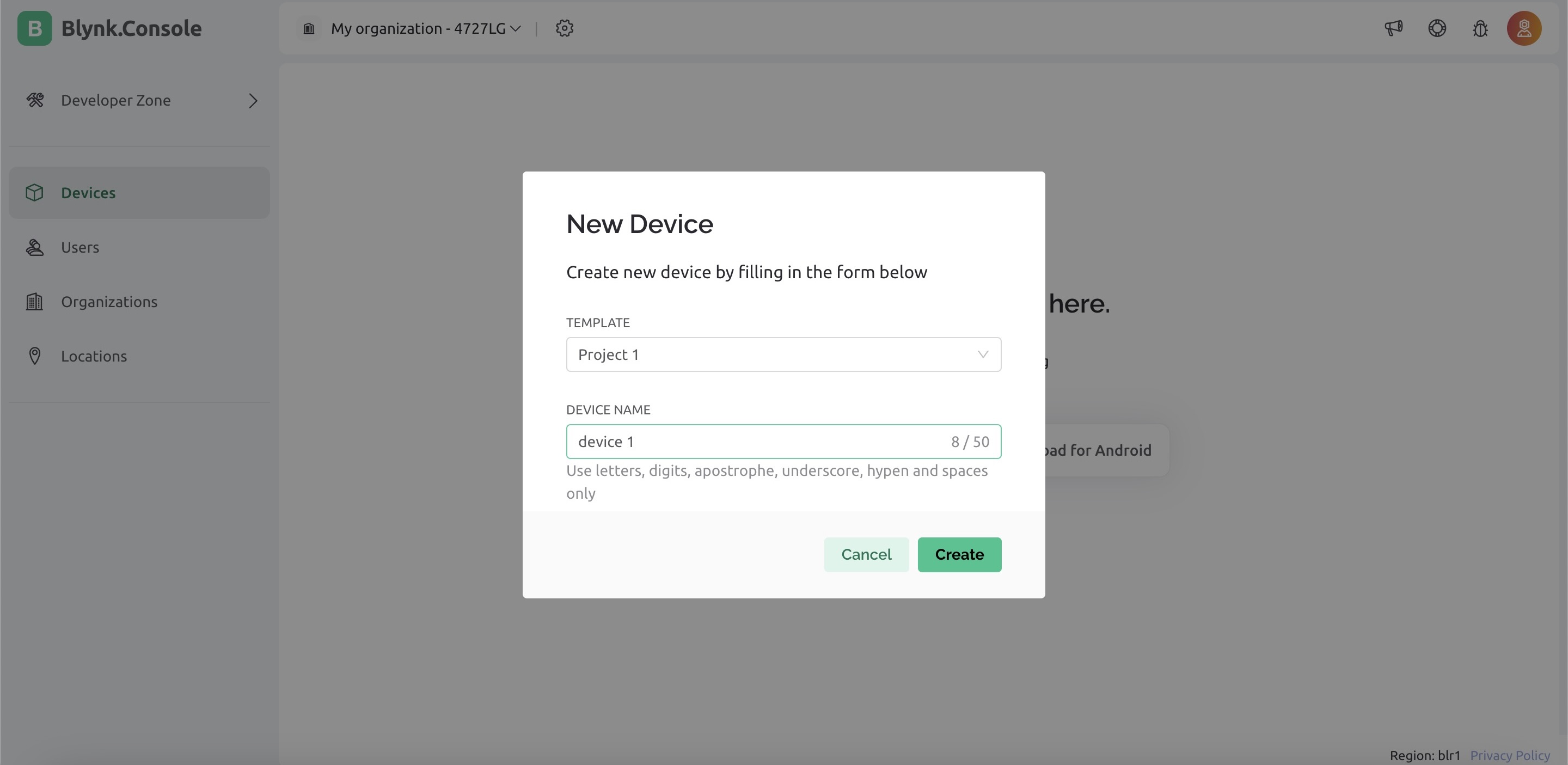
6. Go to Devices on left > New Device > From template. Select the template that you previously created and assign a name to your device.


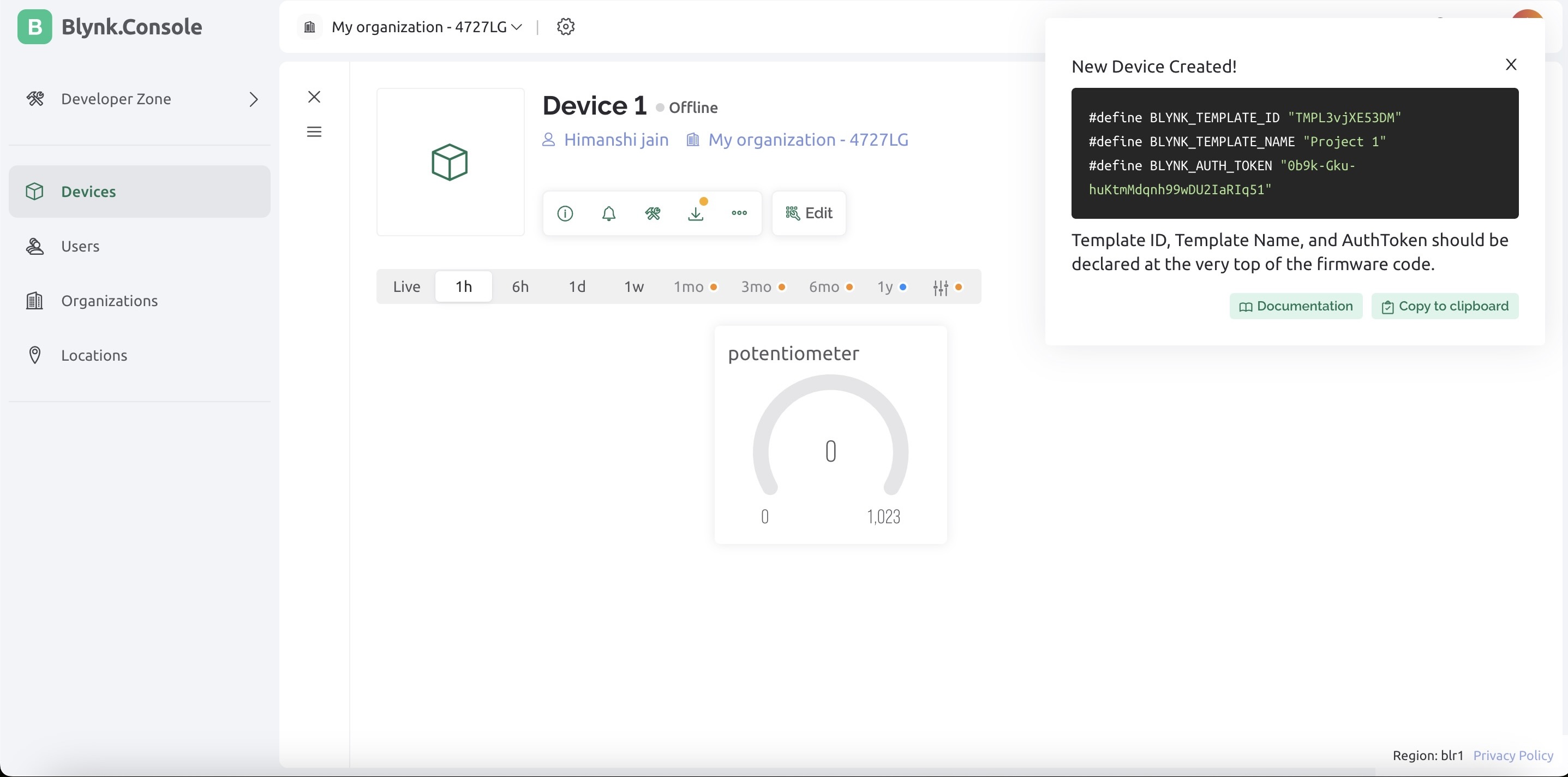
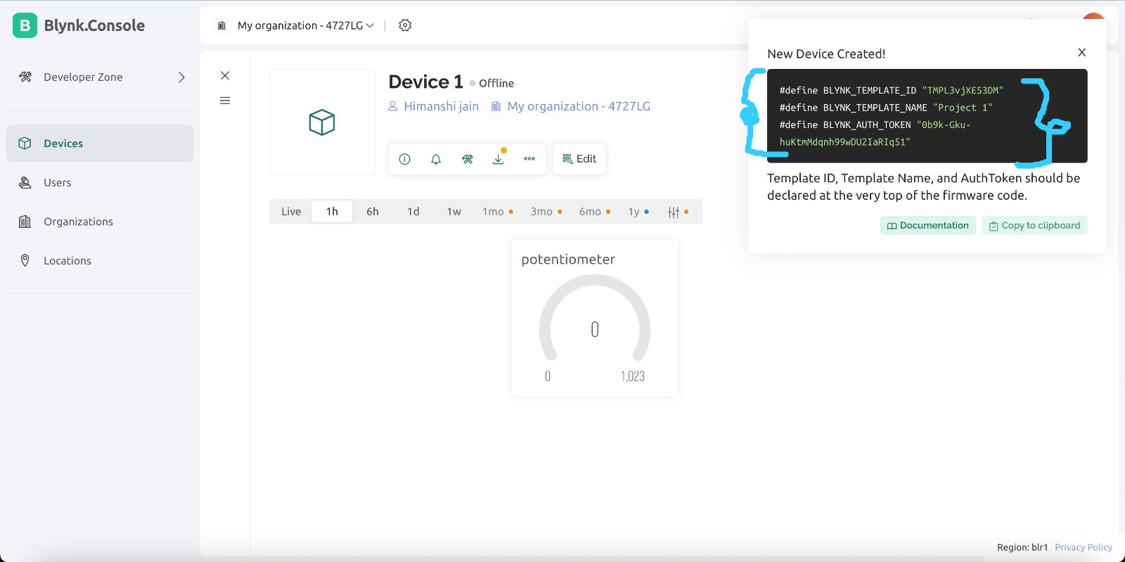
7. Once you create your device, you’ll get the following screen
Copy the 3 parameters in your arduino sketch.
Similarly, login into the mobile app. Add widgets and Datastreams.
8. Open the mobile app and you will be able to see a device already, no need to add a device, click on device 1
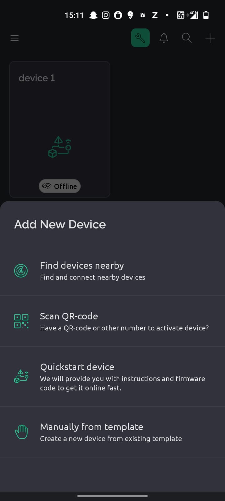
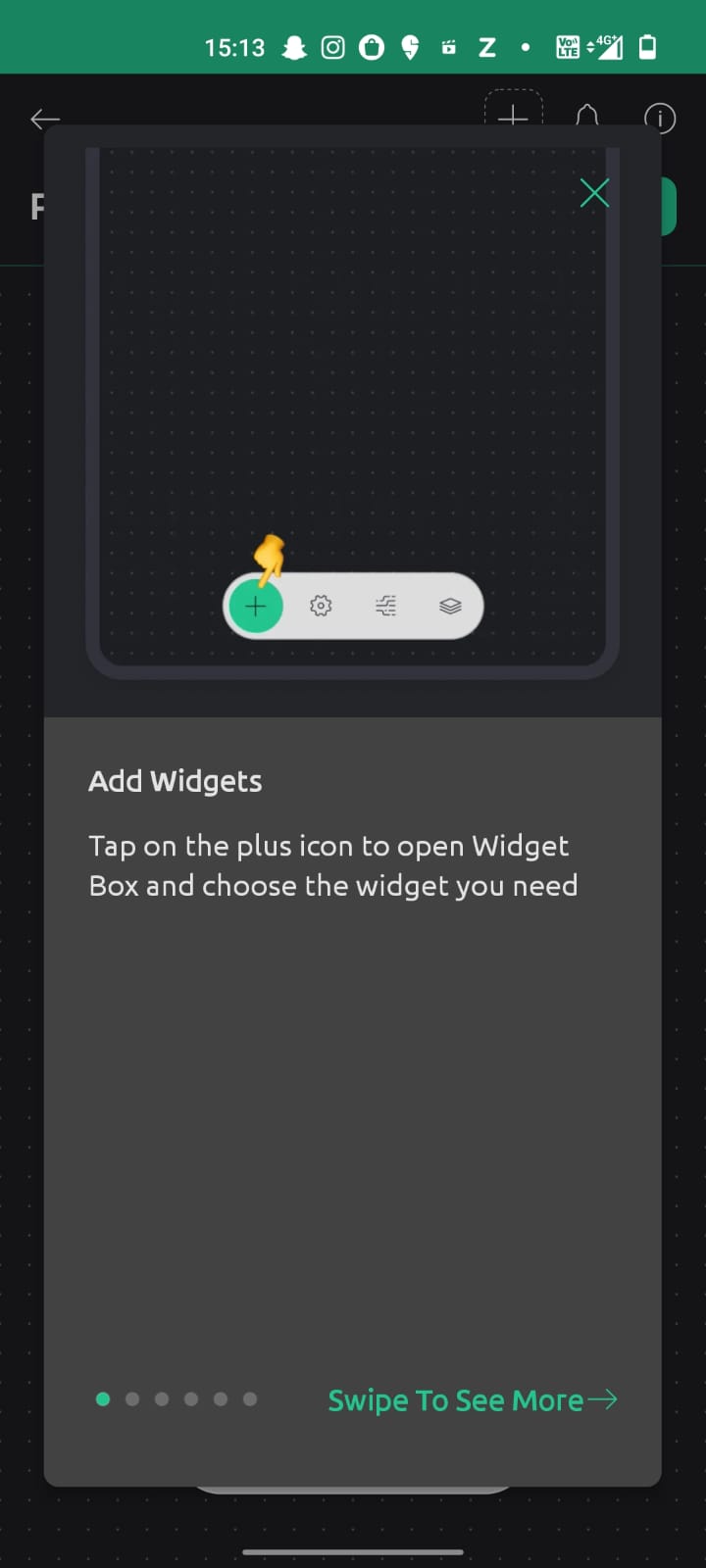
9. After clicking you will be able to see a plus sign that is a sign to add new widget, click on that.
10. After that add new widgt I needed button and a slider so I selected that.
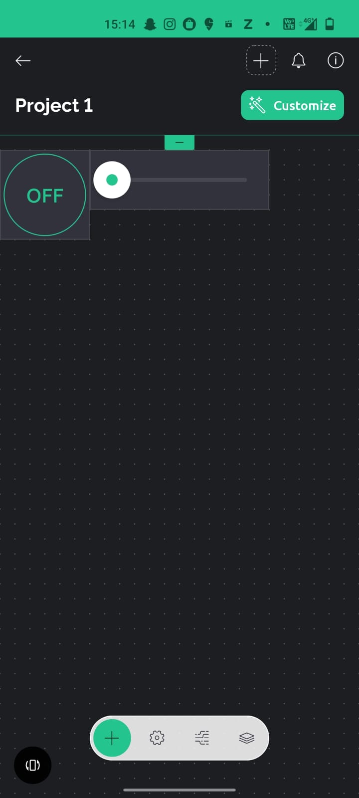
11. You will be able to see button and slider on the page, you can edit and play with size and posistion of the same.
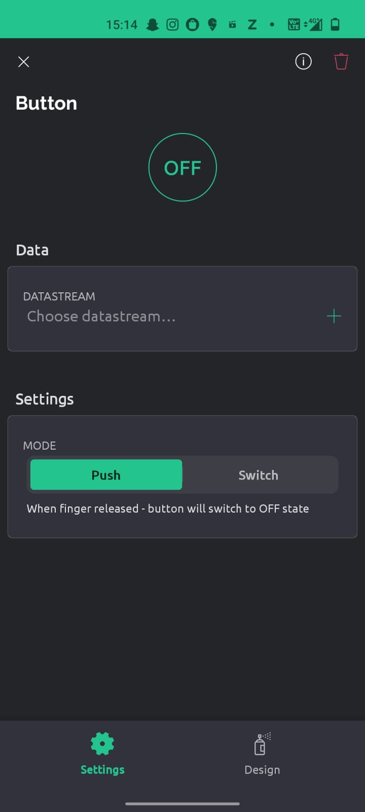
12. Click on the button, go to settings and select switch button as we want that and from the button we want to control led, so in the datastream add that.
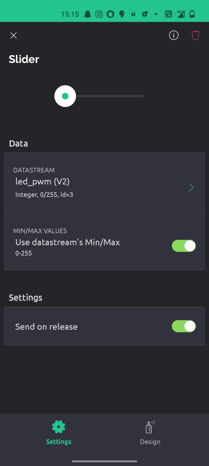
13. Again select slider do the same thing and now select led_pwm.
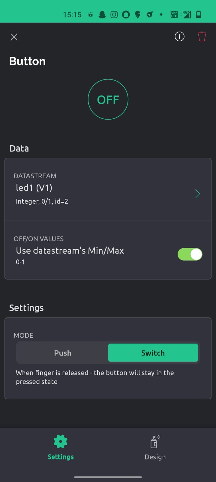
14. Now you can peform the function, the page is ready1
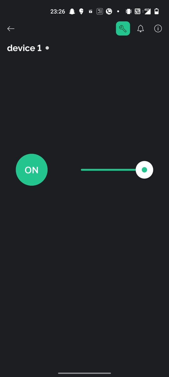
Connections
Circuit diagram
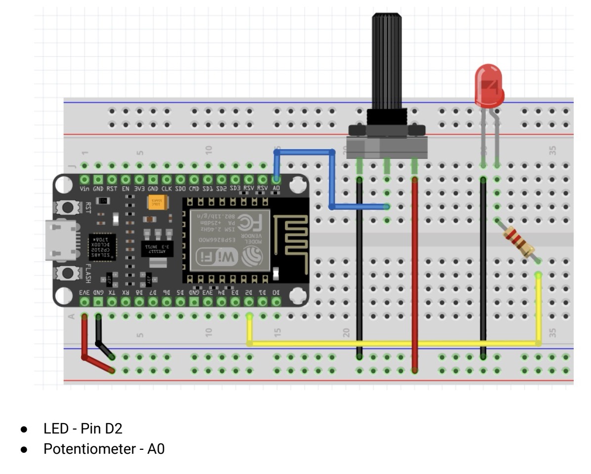
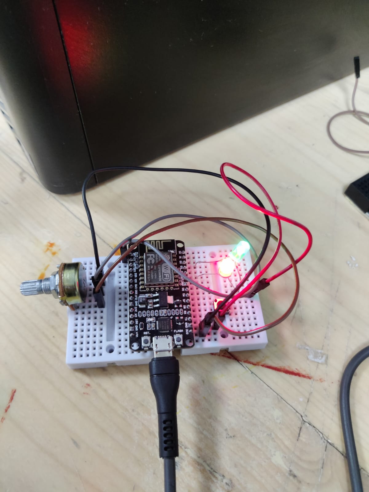
Final working
Controlled by button and slider on phone
controlled by potentiometer
Guage on interface
Code
In this code in line 16 and 17 add your wifi name and password and in line 4, 5 and 6 add the code which you have copied in the clipboard
Learning and Conclusion
This week focused on Interface and Application Programming, where I explored various tools and technologies for connecting hardware with software applications. Through group work, I learned about Processing, P5.js, and Blynk, understanding their unique applications for interactive graphics and IoT projects. Individually, I developed a project using the Seeed Xiao RP2040 and Processing to control an RGB LED based on mouse interactions. Additionally, I created a web server using Blynk to control and monitor ESP8266 devices through a mobile app. These experiences deepened my understanding of interfacing hardware with software, enabling real-time control and visualization of data.