Computer Controlled Cutting
This week, we're diving into computer-controlled cutting, where we'll explore two main machines: the Vinyl Cutter and the Laser Cutter. These machines work like super precise routers, but they're controlled by computers. They're awesome for cutting all sorts of tough materials like wood, plastic, and metal.
The Vinyl Cutter is perfect for cutting sticker papers, while the Laser Cutter can handle a wider range of materials, from paper to leather to acrylic. We're also looking at CNC routers, which are used for cutting wood and plywood. And let's not forget about the big industrial metal laser cutters and engravers.
I've always loved the Laser Cutter—it's one of the coolest tools in the FABLAB. I first tried it out back when I was at Somaiya School of Design. Even though I've used laser cutters before, I haven't really paid much attention to details like model checking and joint clearance. So, this week, I'm excited to learn more about how to use the RIIDL laser cutter like a pro.
Exploring the RIIDL Laser Cutter
To grasp laser cutting and how the machine operates, let's begin with the fundamentals.
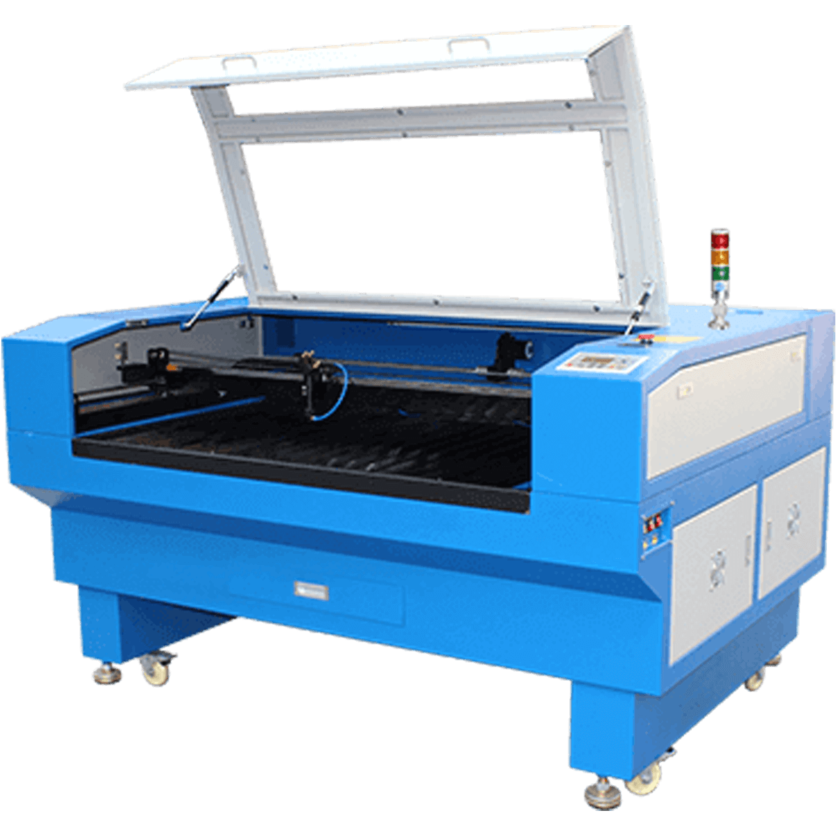
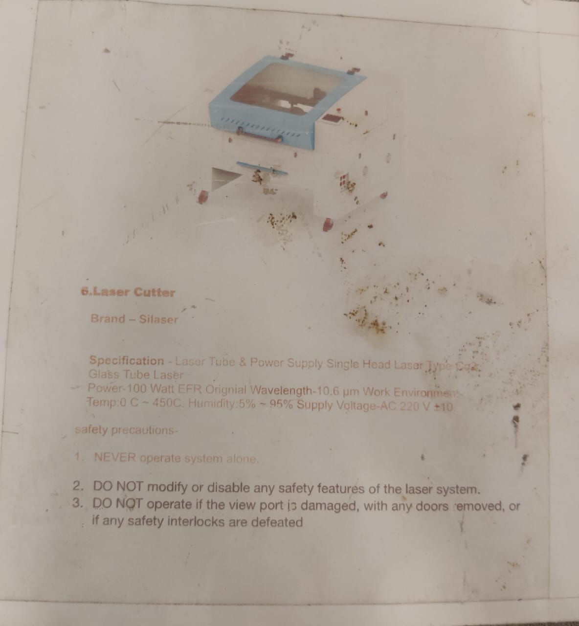
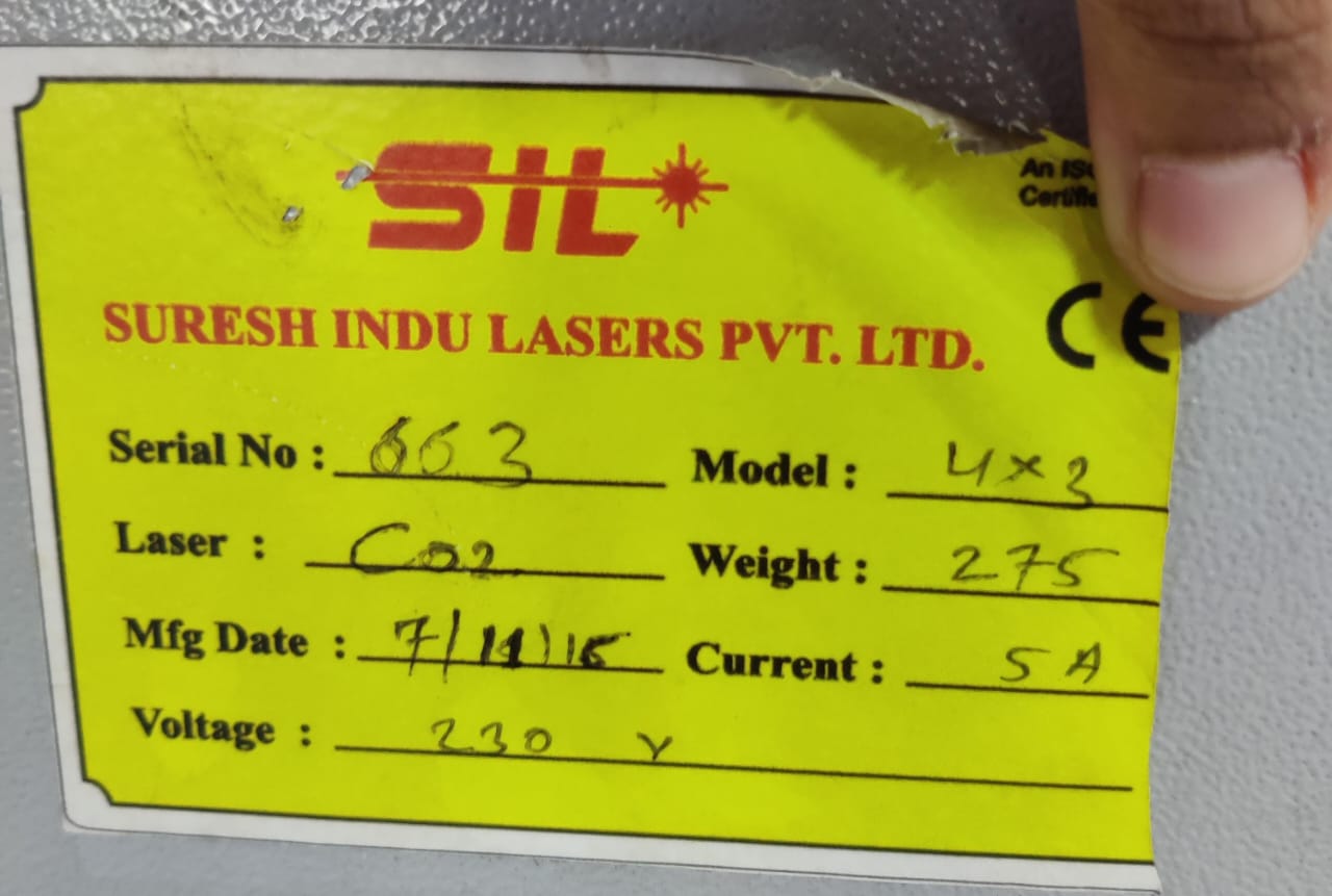
Our laser cutter machine at riidl is a CO2 Laser cutter from SIL (Suresh Indu Lasers Pvt. Ltd). The details of the same are as follows:
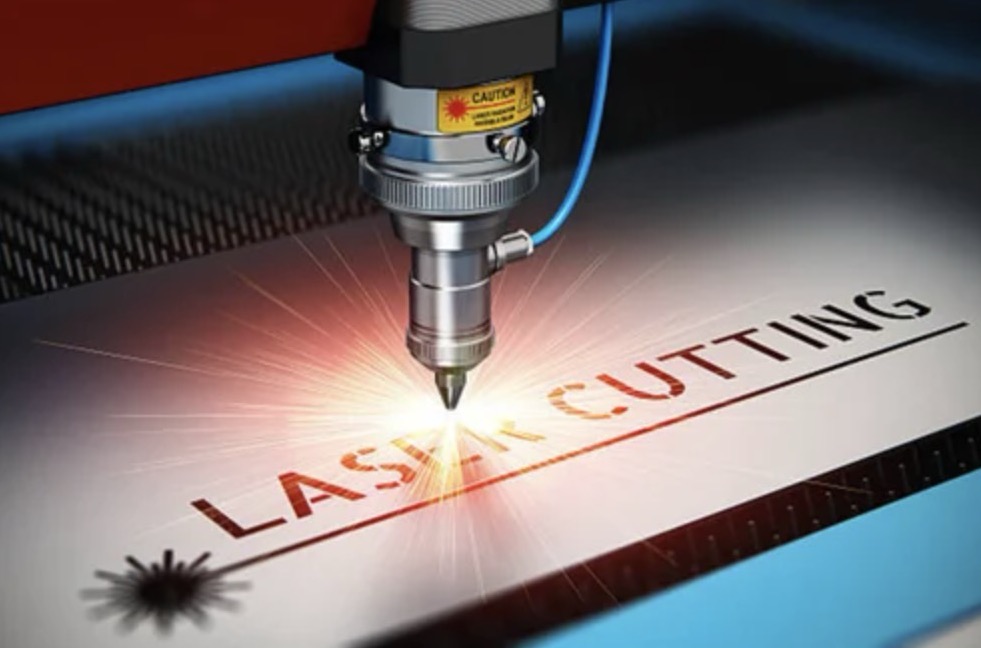
Laser cutting is a method that employs a laser beam to vaporize materials, resulting in precise cuts. Initially developed for industrial manufacturing, laser cutting has now become accessible to schools, small businesses, architects, and hobbyists alike. The process involves guiding the intense beam of a high-power laser through optics to achieve the desired cuts.
Types of Laser cutters
The three main types of laser cutters are as follows:
CO2 laser cutter:
CO2 laser cutting machines use a special gas mixture, including CO2, helium, and nitrogen, to create a laser beam. This beam has a wavelength of 10.6mm. CO2 laser cutters are popular because they're efficient and affordable. They can cut materials like glass, plastic, leather, wood, and acrylic.
Crystal Laser Cutter:
Crystal laser cutters use a different method, generating beams from a material called Neodymium doped yttrium ortho vanadate. These cutters have smaller wavelengths than CO2 lasers, allowing them to cut through thicker materials. They also provide better focus and higher intensity. However, their parts may wear out due to the high power they use. They can cut plastics, metals, and ceramics.
Fiber Laser Cutter:
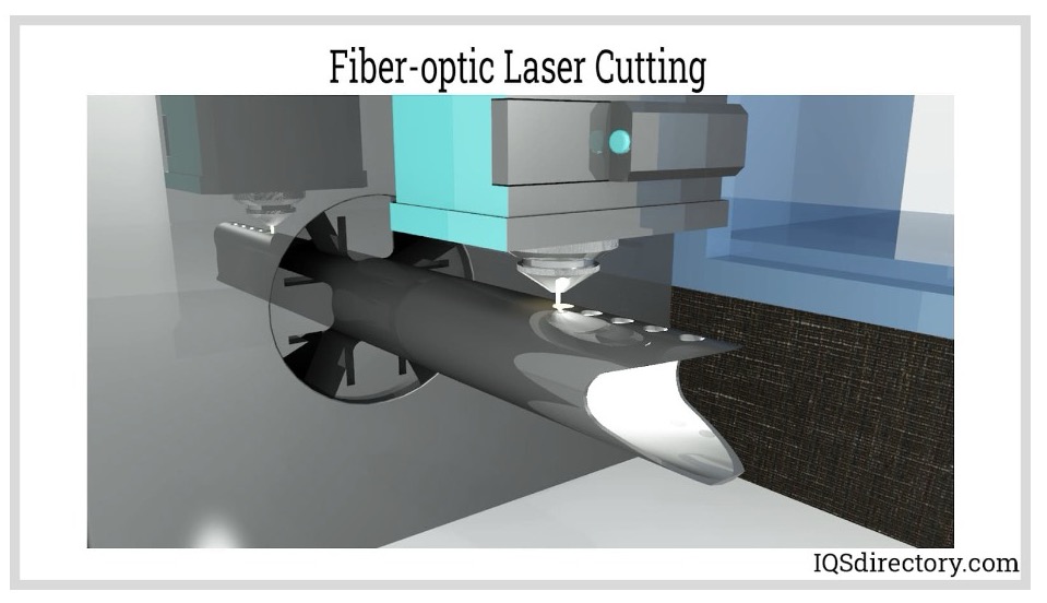
Fiber laser cutters use a process where a seed laser is amplified and magnified using special optical fibers. Another name for them is solid-state lasers. Fiber laser cutters have several advantages, including the ability to cut reflective and conductive metals, three times the efficiency of CO2 lasers, and the absence of movable parts. They're suitable for cutting metals and organic materials.
What is Parametric Design Kit?
A parametric design kit is like a toolbox for designers. It helps them make things where changing just one thing can affect the whole design. Imagine you're building with blocks, and if you change the size of one block, all the others change too. That's what parametric design is about. It's like having a magic wand that lets you tweak and adjust things easily, but the overall shape stays the same. So, designers use these kits to create cool stuff that can adapt and change without too much fuss.
Exploring Laser Cutter Traits
To recalibrate the laser cutter's settings, my teammates Tejas and Siddhart I focused on the following aspects for testing.
1. Focus
In laser cutting, the focal point plays a crucial role in optimizing the transmission of energy from the tube to the workpiece. When the focus is off, the machine's cutting efficiency diminishes, reducing the beam's effectiveness on the material.
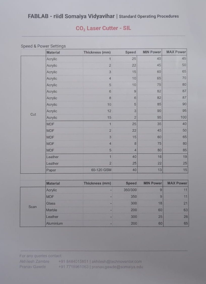
2. Power x Speed settings
The power of a laser is not influenced by its speed; however, achieving an ideal balance between the two is crucial for achieving the best outcomes. Generally, high speed with low power is used for engraving, while low speed with high power is employed for cutting. A chart outlining the appropriate speed and power settings for materials of specific thicknesses has been developed at RIIDL, as illustrated below:
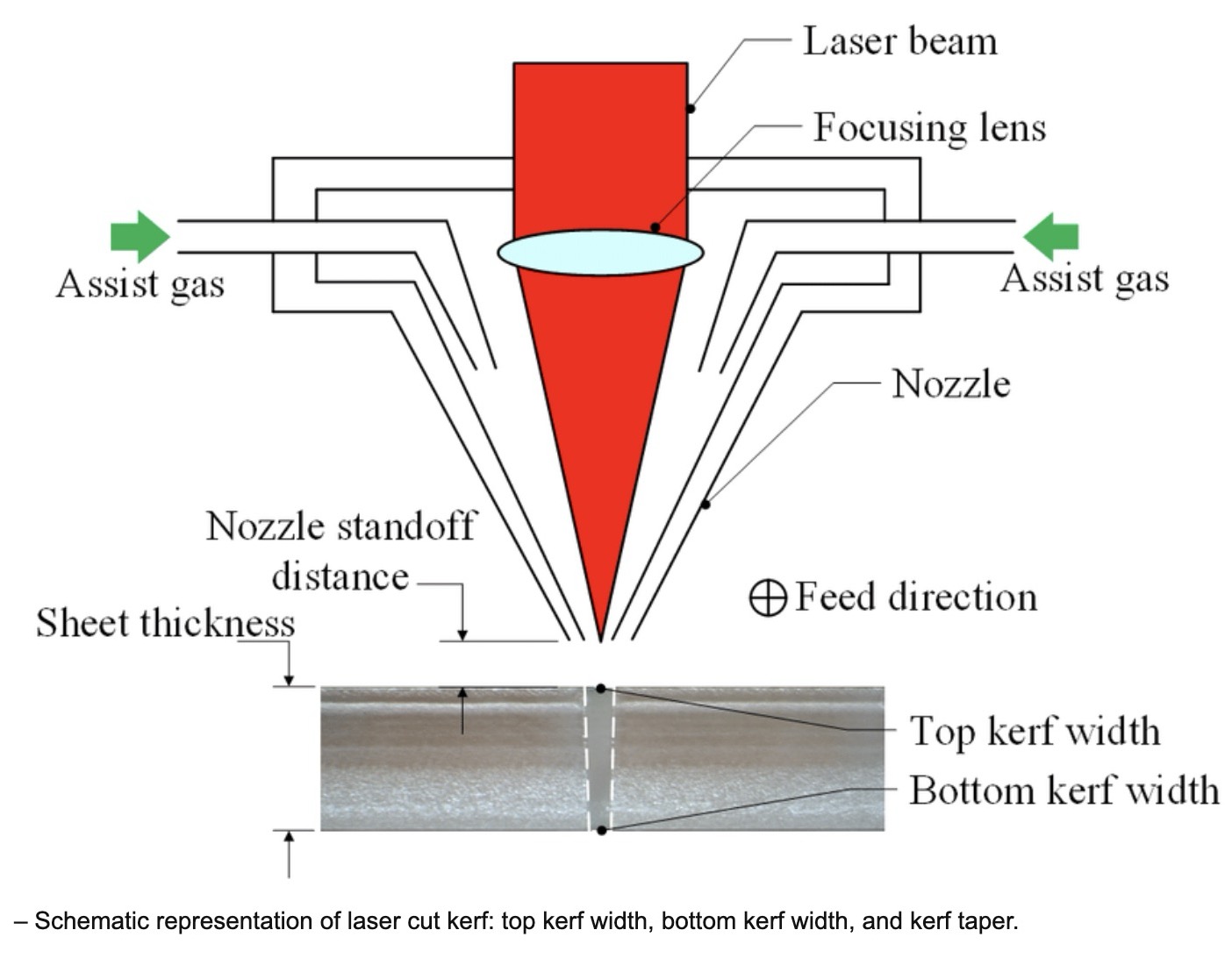
3. Kerf
When the laser makes a cut, it vaporizes a portion of the material, creating what's called the laser kerf. The width of this kerf can vary between 0.08mm to 1mm, depending on factors such as the type of material and other environmental conditions.
4. Joints and joint clearance
Finger joints (also known as box joints), mortise and tenon joints, and slotting joints are frequently utilized in laser-cut structures due to their simplicity and robustness. To achieve the desired fit, whether it's clearance fit or interference fit, you'll need to assess the efficiency of your laser cutter machine through trial and error.
Parametric design kit
The latter portion of this week's task involves creating, laser cutting, and documenting a parametric construction kit.
Finger joints for making the box
To make the lamp, we need to first check how to make the finger joints which fits perfectly
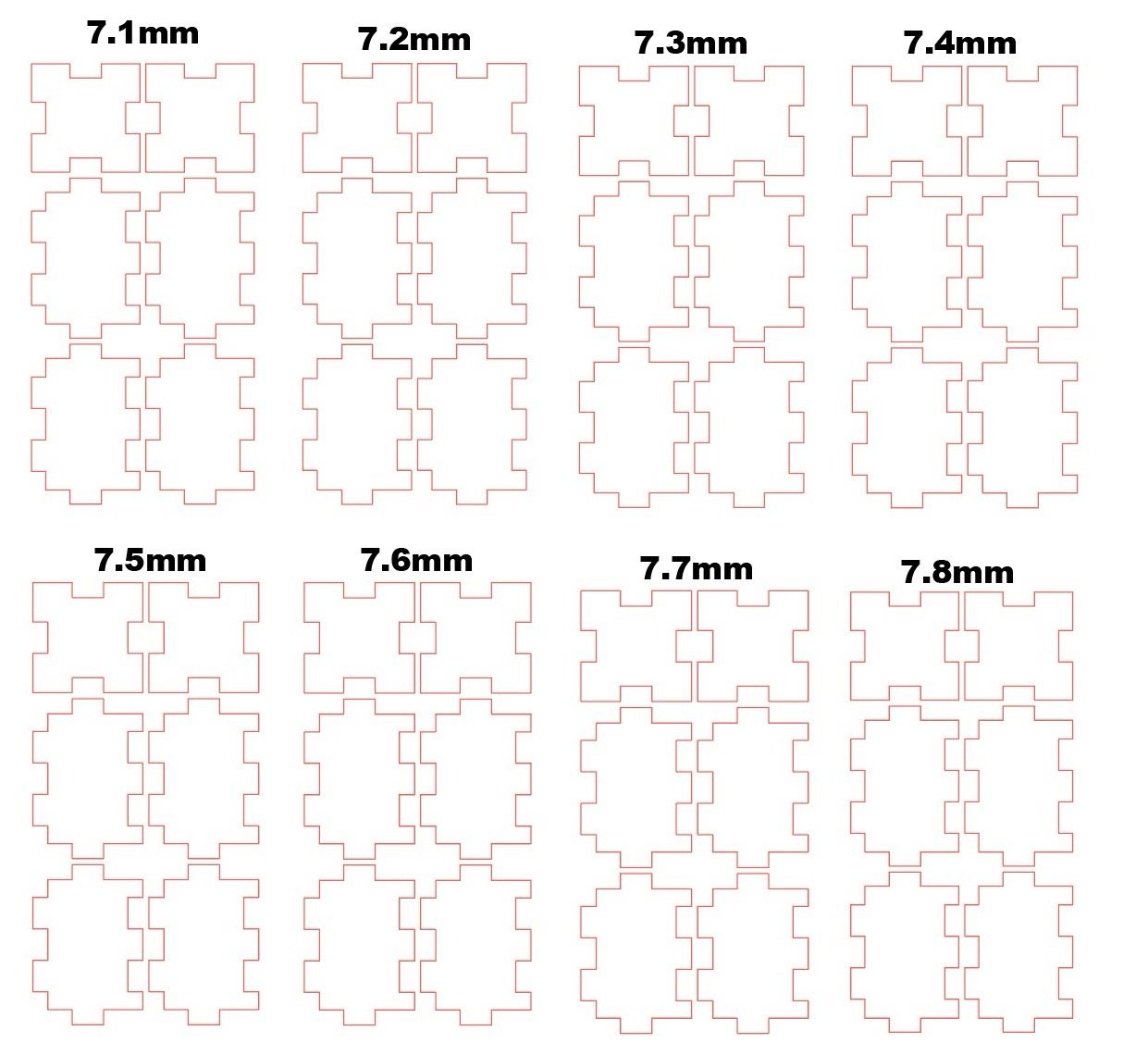
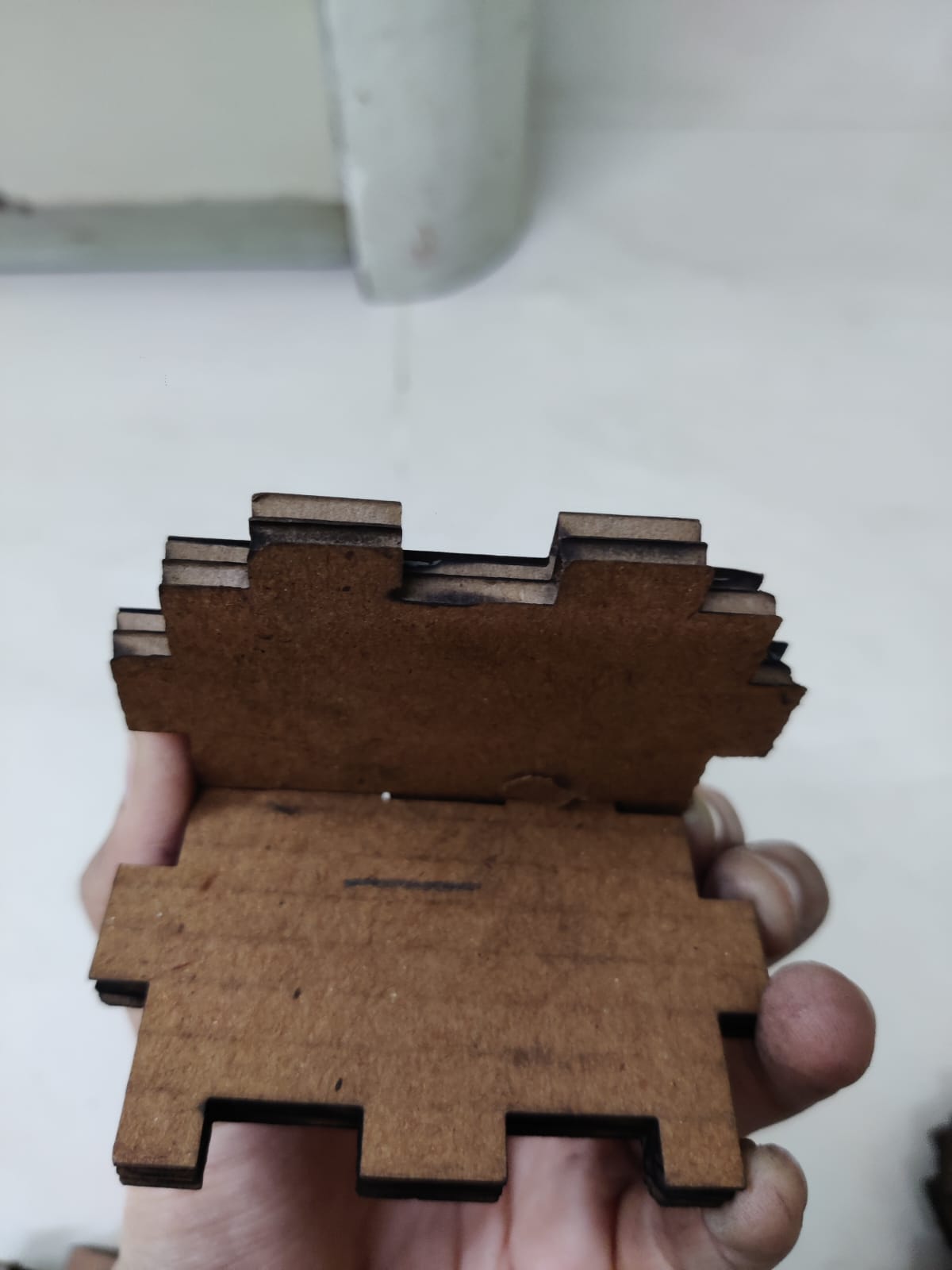
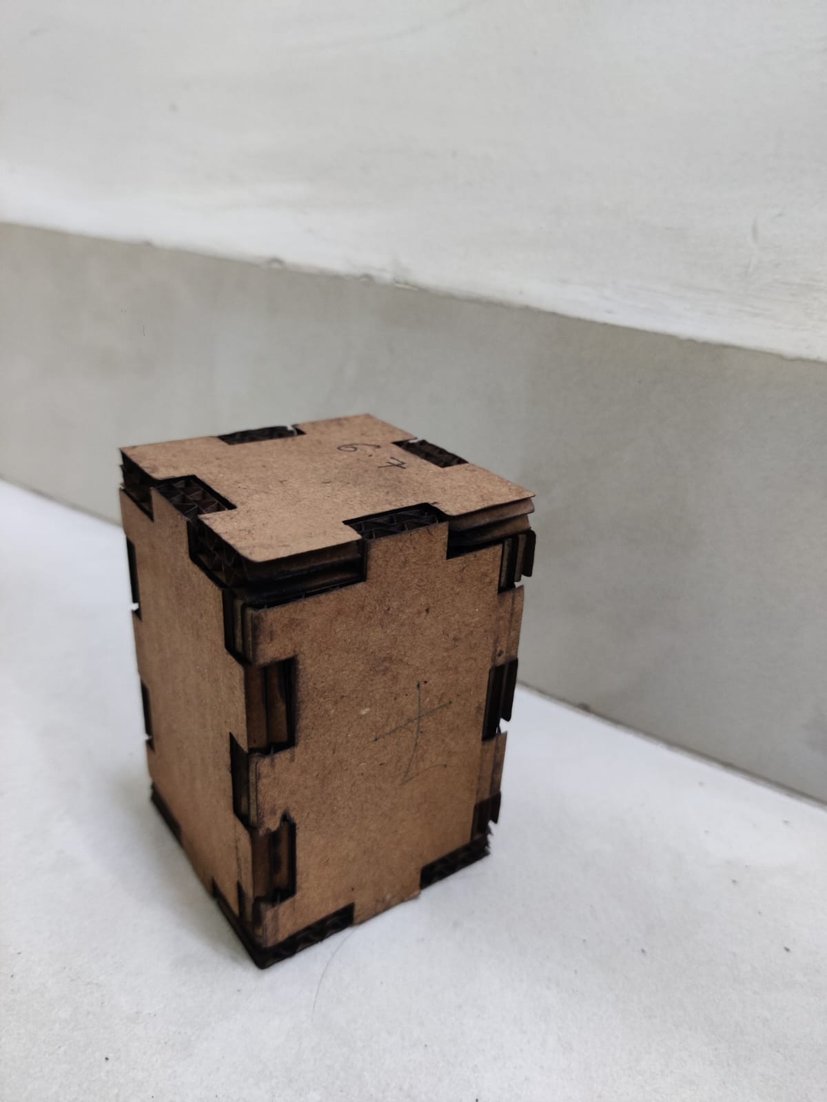
I wanted to make a box with a finger joint so we selected the material as 5mm corrugated sheet ply which was approximately 7.3mm in thickness.
Initially we made a file of 7.1mm to 7.8mm
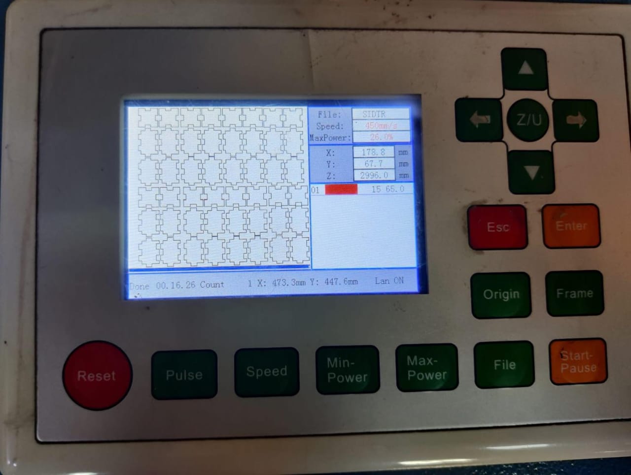
The speed power for the file I used was of 3mm mdf, the min and max- speed power I used from the image shown below
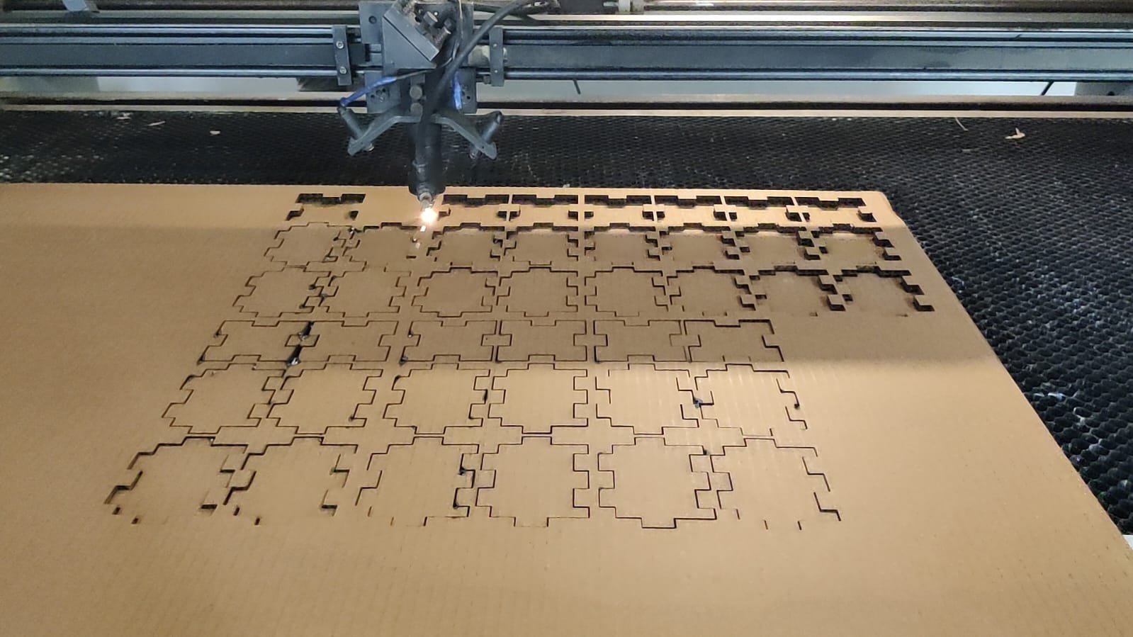
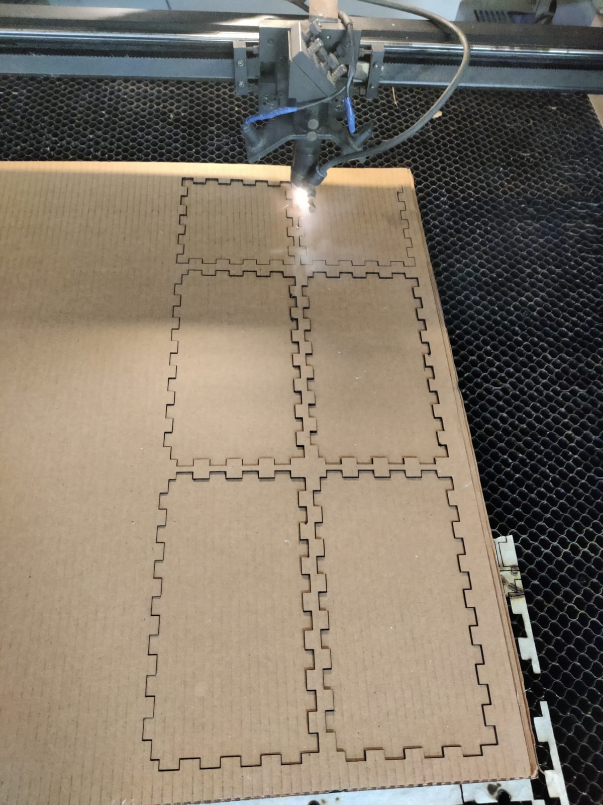
I inserted the file in the machine according to the laser cutting settings and adjusted the bed and started the cutting.
To see the video of cutting the pieces click below
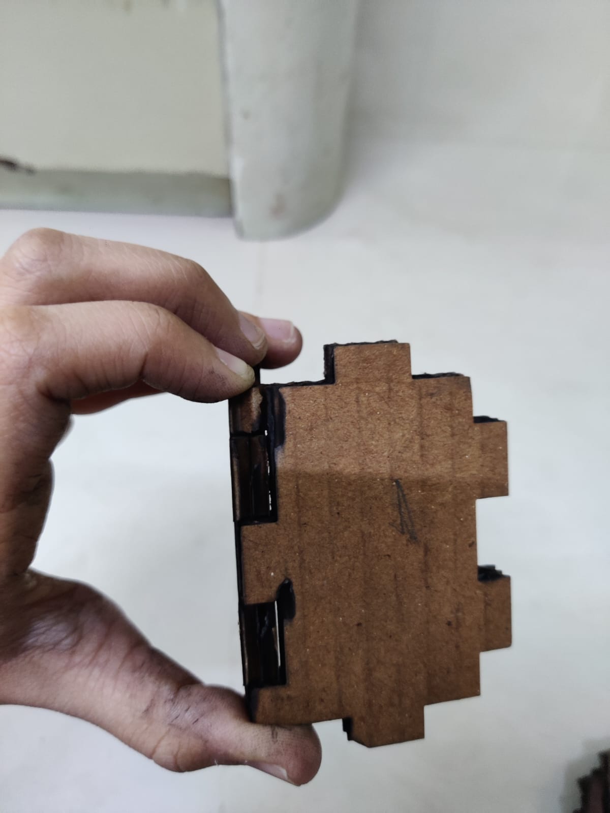
After cutting the file I tried fitting 7.1mm first, when I were trying this I realised 7.1mm was only loose and was not fitting so I did not try all the others
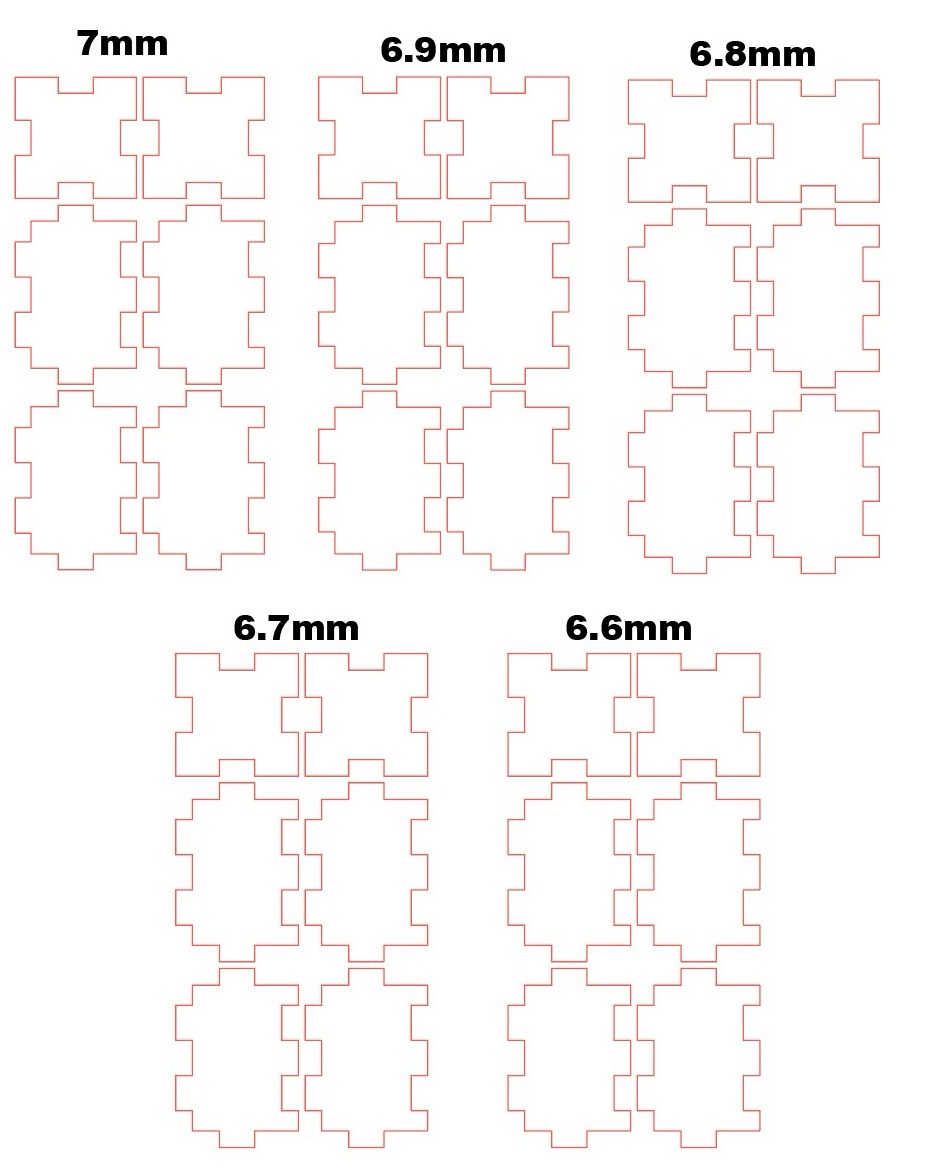
After that I made a file of 7mm and went down till 6.6mm
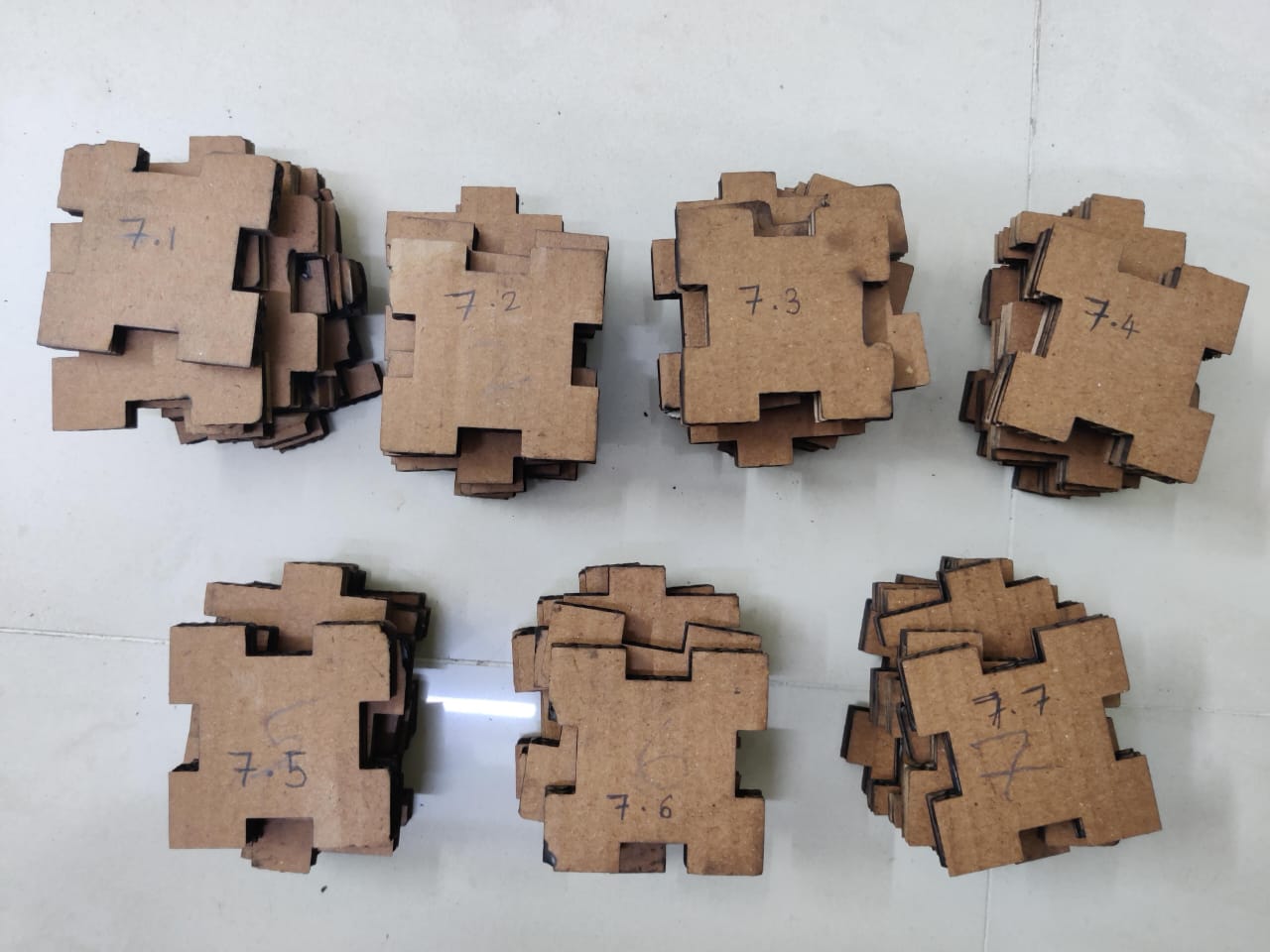
When I started fitting these pieces 6.6mm was fitting, but here I realised I was making the entire box small but the error here was we wanted to only decrease the width and height of the slots because everytime the difference was 0.2mm.
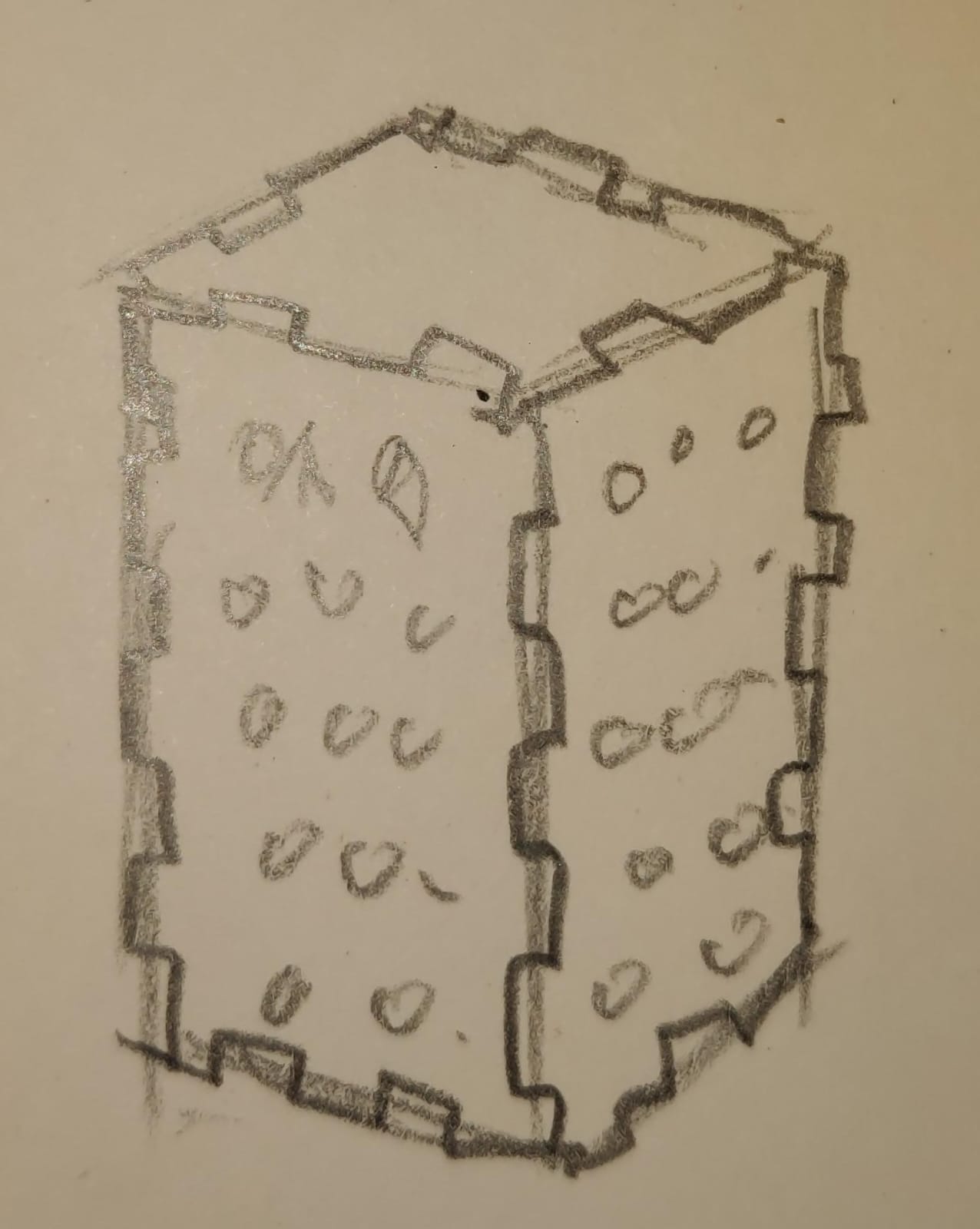
Step 1: Ideation
After thinking hard about what exactly I want to do as a parametric design kit, inspired by a lamp design, I decided to try out a finger joint parametric design kit.All the iterations and design changes along with the kerf of the finger joined was done as a group assignment, you can check it here. The initial ideation and plan is shown in the figure below:
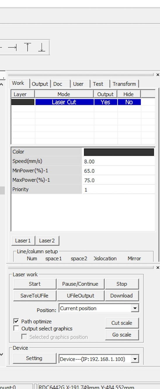
Then we inserted the file in RD works, how to use the laser cutting from start to end is explained below and set the speed power as shown in the image below:
Step 2a: Making Case with finger joints
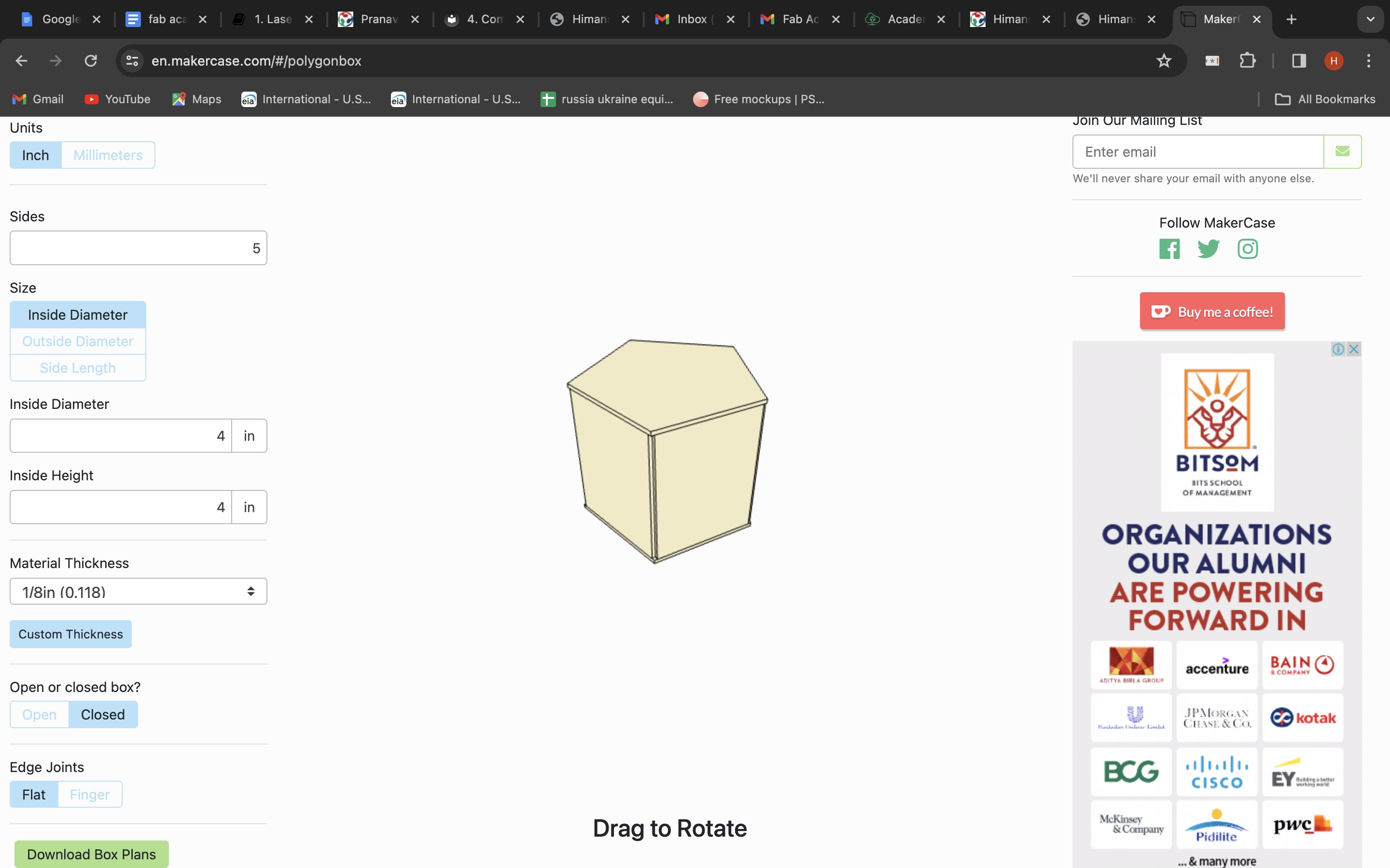
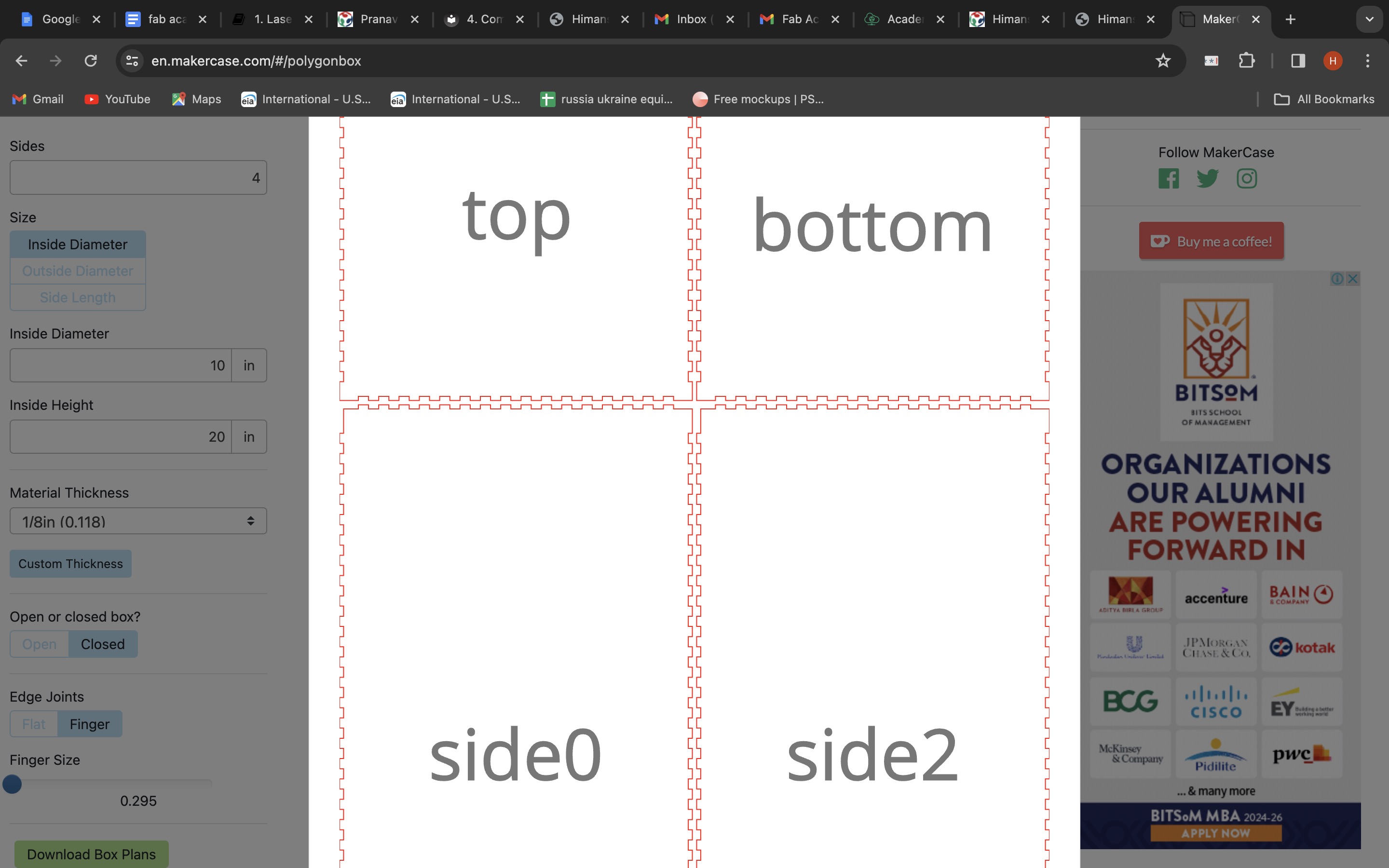
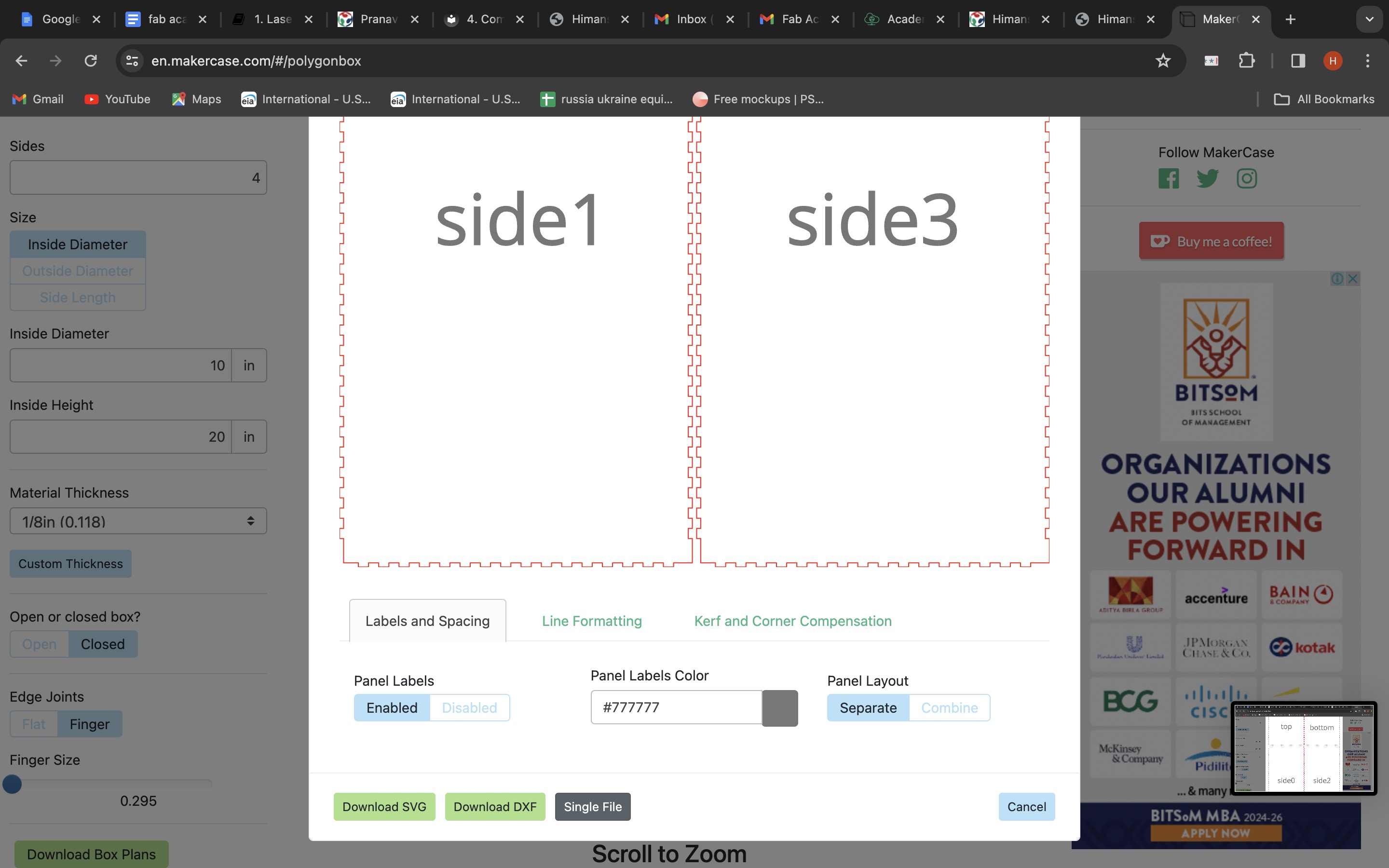
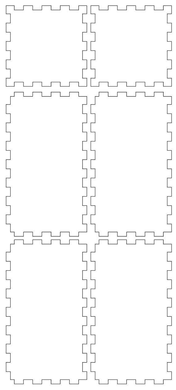
I used Make a case online tool which helps to make finger joints. You need to mention number of sides, inner, outer diameter or side length- depending on what you are making, specify material thickness and you have an option of edge joint or finger joint, select finger joint and you can adjust finger joints, the more joints the better outcome. Then you can click on download and there is an option of different formats such as SVG, DXF,or a single file. Here if you want you can manually change label and spacing which includes- colour of boxes, you want boxes to be combined or seperate, you can also change line formatting and kerf and corner compensation which has multiple options again.
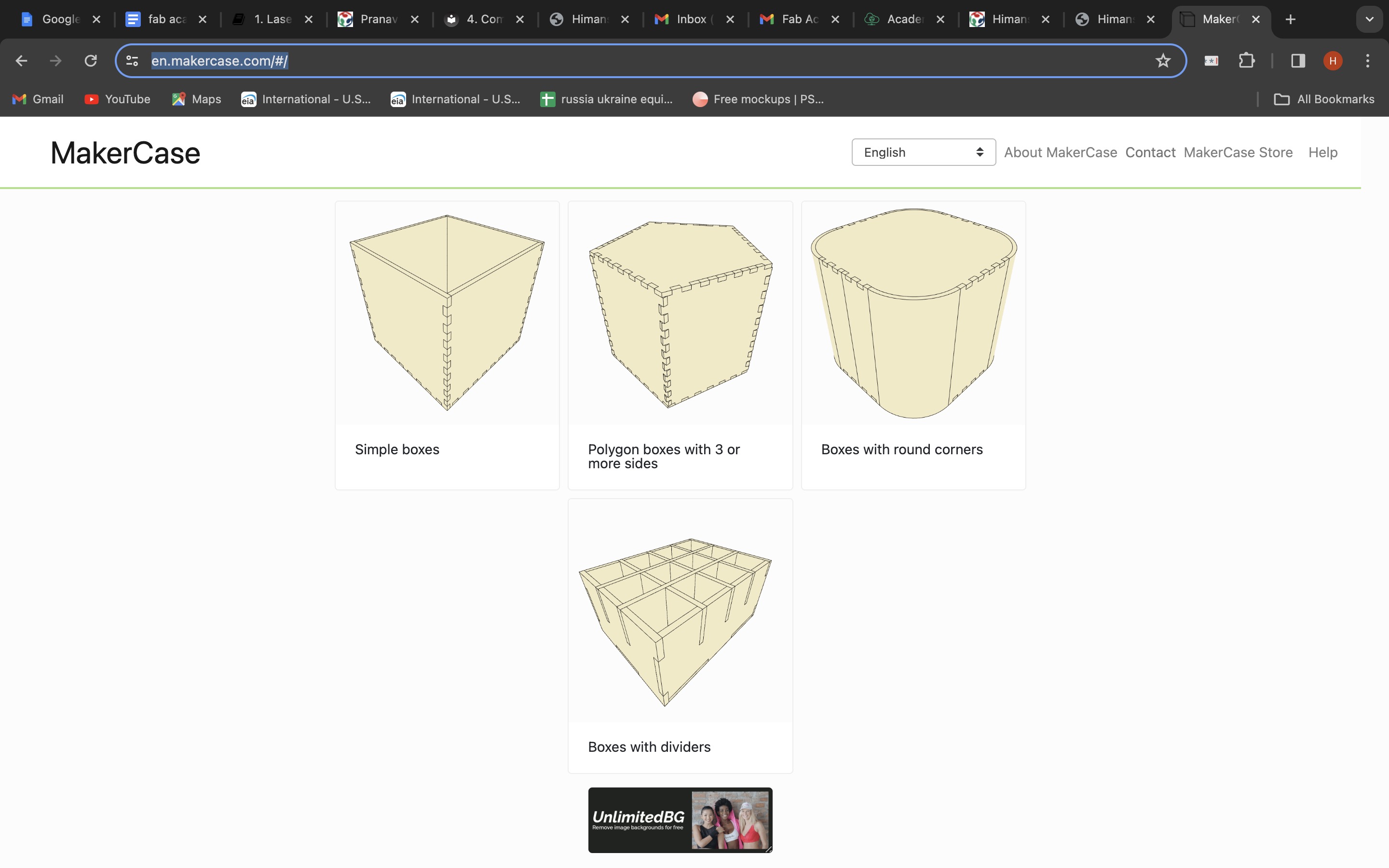
Site for making the Case
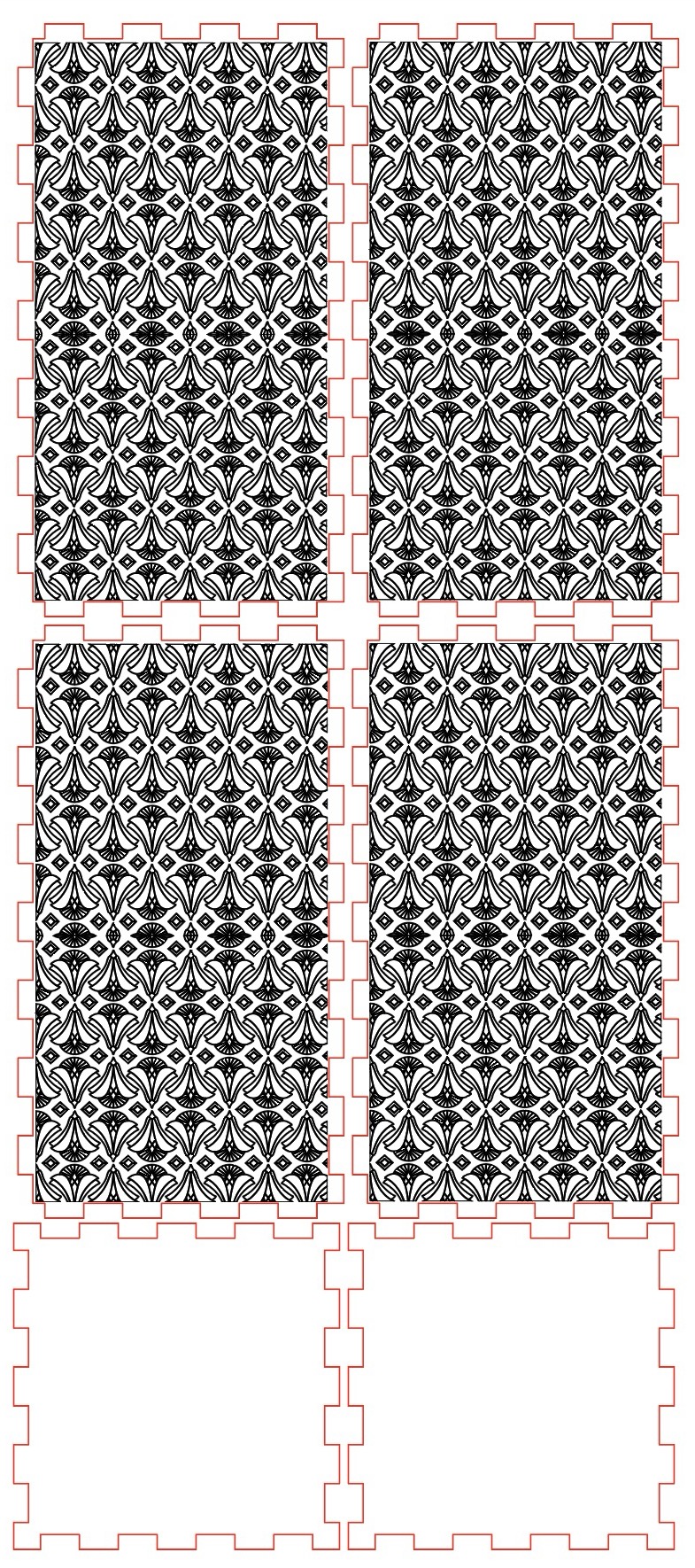
Make a caseAfter downloading the box you can open the SVG file in your illustrator and if you want patterns on boxes, make the design annually or you can take design from an online site and convert it into a vector. After making the design, convert everything into 1 colour and give stroke thickness from 1pt and not less than that as it will sometimes not show on your laser machine controller.
Then save and export the file as DXF and open your file in RD works.
Step 2b: Design
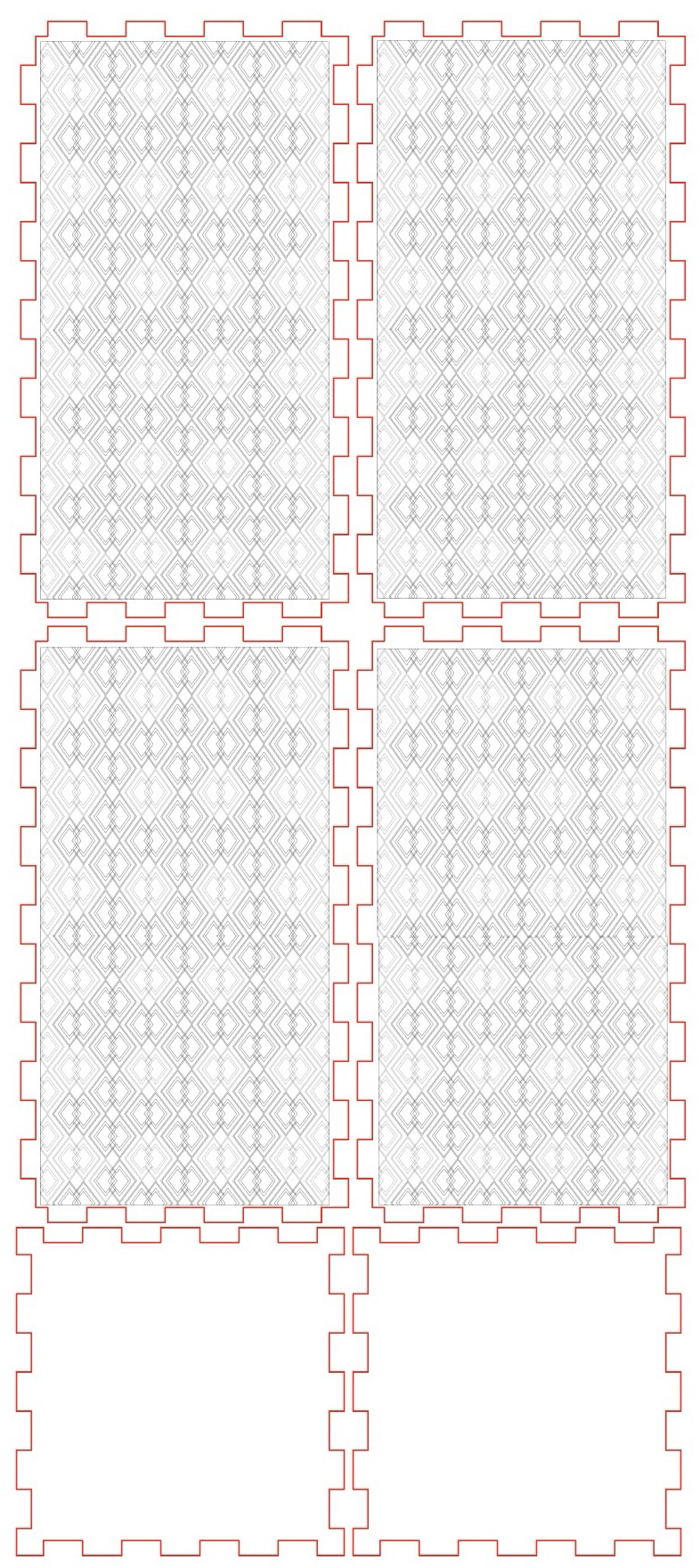
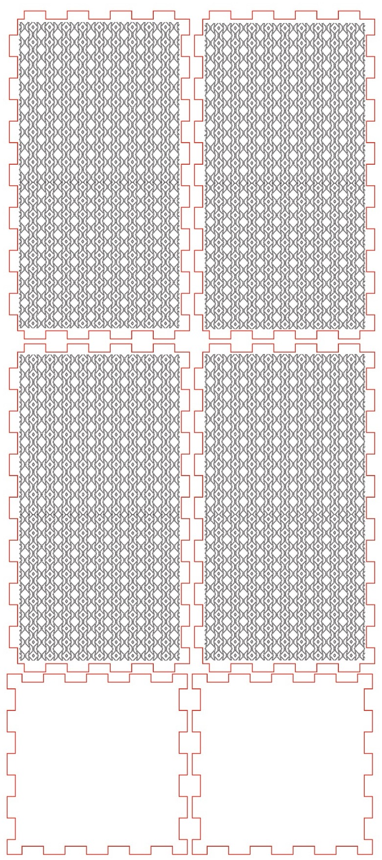
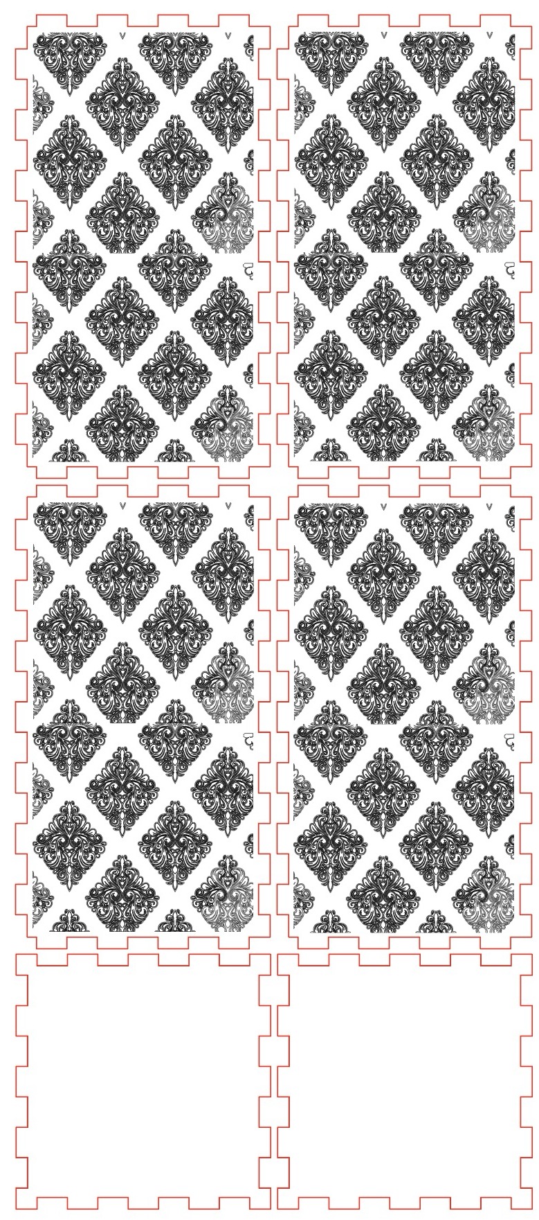
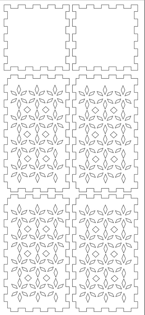
Initially I made a very intricate pattern on my lamp, I inserted that pattern into RD works and then my mentor told me that laser cutting will not give you such intricate pattern as there was only 0.3 mm distance between patterns, so it was not possible to cut. Below is my old design file
Next step was to design it on any software, I did it in illustrator. One needs to try it out with respect to the laser kerf for a perfect joint. Design can also be made on other vector based softwares like Corel Draw, directly on RD works or Fusion or Solidowrks.
Step 2c: Installing RDWorks
RUIDA RDWorks is a software used for controlling laser engraving and cutting machines manufactured by RUIDA Technology. The software provides users with a graphical user interface to create, edit and execute laser engraving and cutting jobs. It is compatible with a wide range of vector formats including DXF, AI, PLT, and DST. The RDWork v8/LaserWorks v8 system supports the following formats: Vector format: Dxf, ai, plt, DST, dsb, and related formats. Bitmap format: BMP, jpg, gif, png, mng, and related formats. RDWorks can be installed at the link here
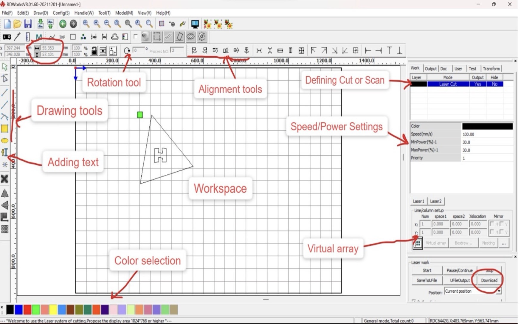
RD worksStep 2d: Exploring RDWorks
The interface RDWorks software is quite intuitive. One can directly make file in Rd works or put a file in Rd works. After opening the file the center part which you can see is your workspace. There are different tools like one can change the measurements, drawing tool, rotation tool, allignment tool, adding text, colour selection, depending on the material you can adjust the speed power as shown in the image above, There is also an option of cut or scan, scan helps in scanning or engraving the file and cut cuts the entire file. A quick overview of the same is shown below:
Step 2e: Putting the file on Rd works
I designed my file of lamp on illustrator (which is seen above) along with the measurements which I wanted.
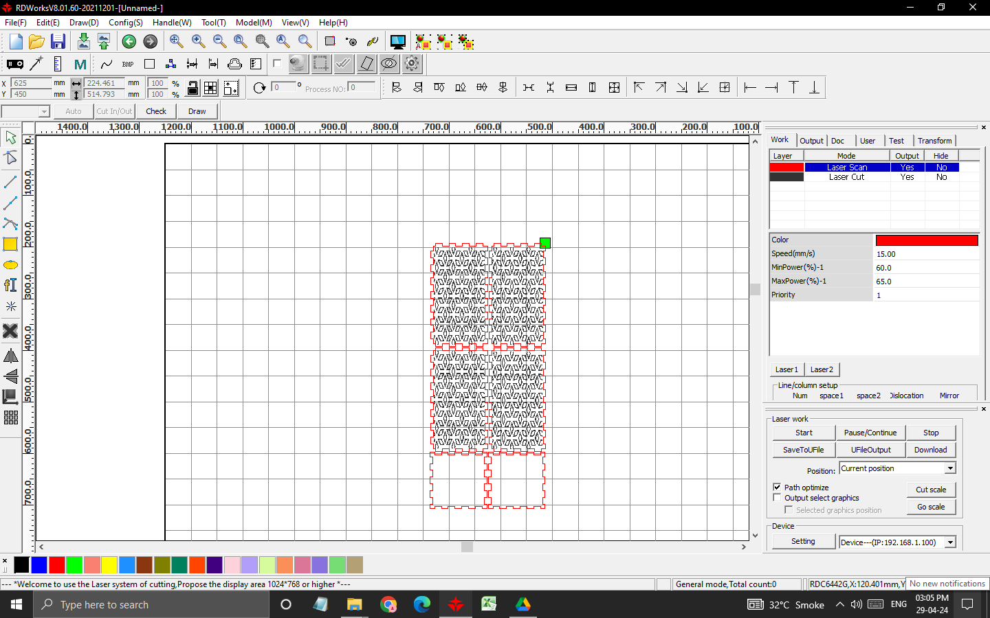
Step 2f: Setting power and speed
You need to set the speed and power here. The material I used was 5 ply corrugated sheet which was approximately 7.3mm thick and thus accordingly speed and power values as shown below.
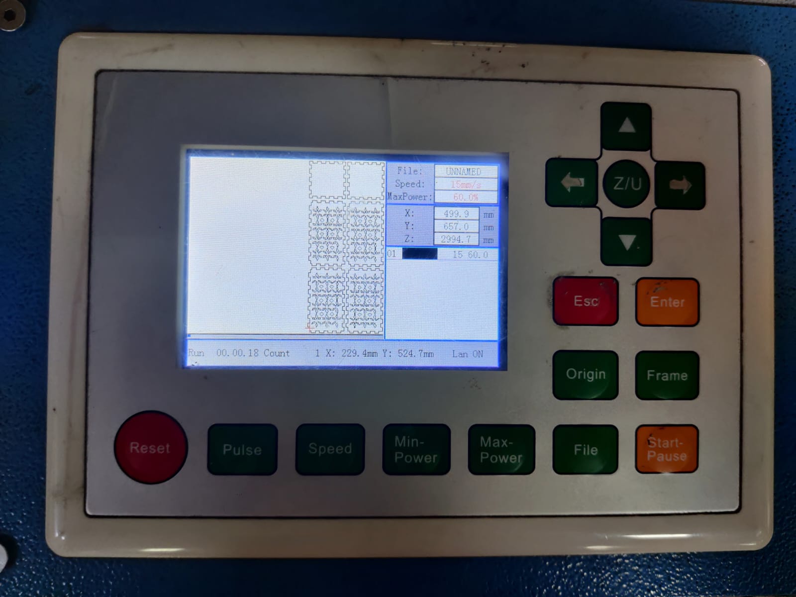
Step 2g: Downloaded the file on machine
After setting speed and power, and cut or scan option, click on download and it will download the file on machine.
Click on file and check your file name and press enter, your file will open, check your file whether everything is there are not.
Adjust the bed according to the material, if you want to take your bed downwards press ZU and left arrow together, if you want it above press ZU and right hand side arrow together.There should almost be 6mm gap between the laser and the material, set the origin by clicking on origin.
Check the frame it shows how much piece of material it is going to cut, basically the outer measurements of your design. Then press start.
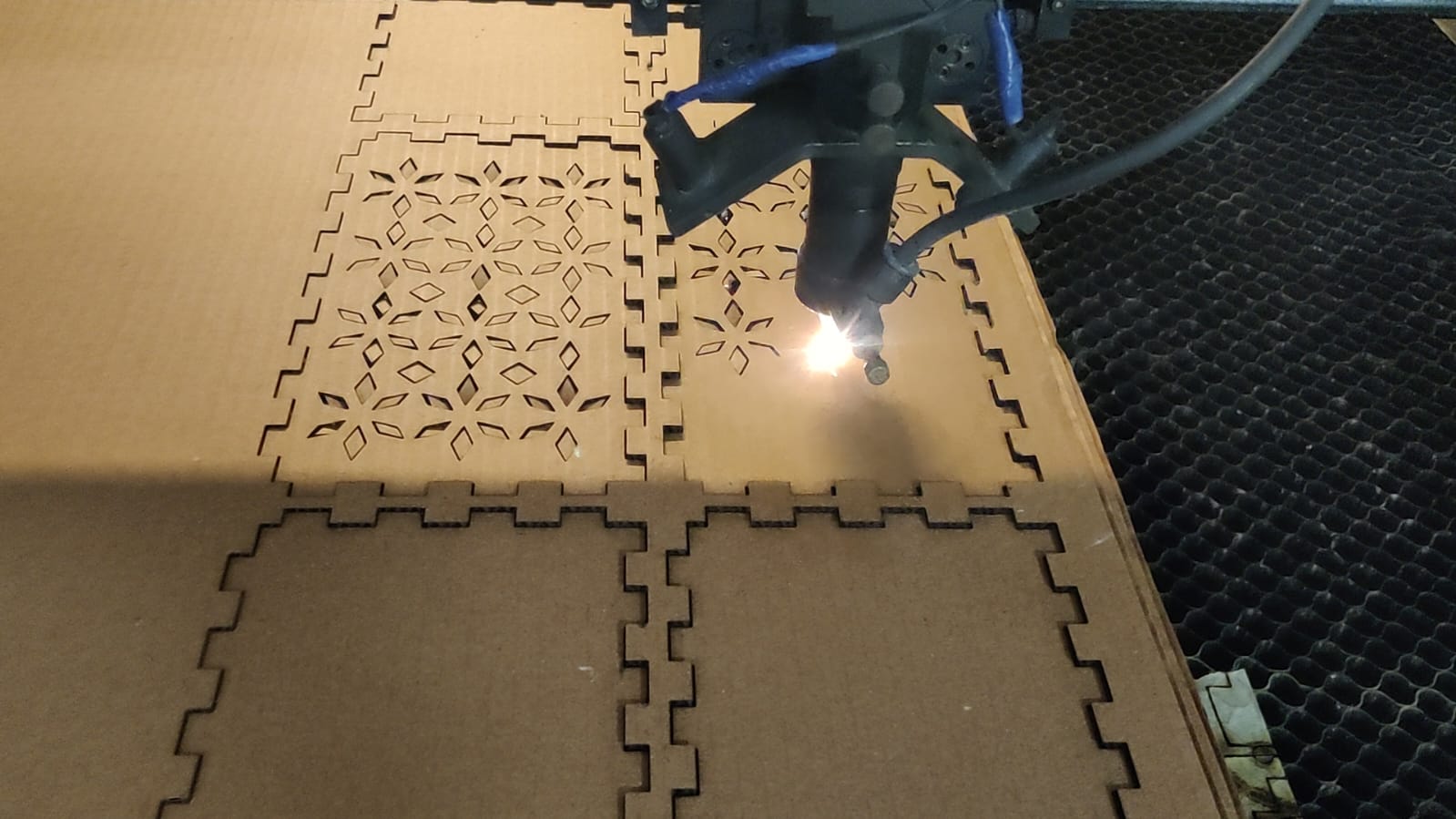
Step 2h Cutting
Check the material whether it is cutting or not, you can check hta by looking at the material whether it is coming a bit up or not, or at the end after the laser stops, don't shake the main material slightly take that material above and check whether the pieces are cut or not, if it is not cut then start the file again by pressing start on the machine, without changing anything not even the origin.
To see the video of cutting the pieces , click below:
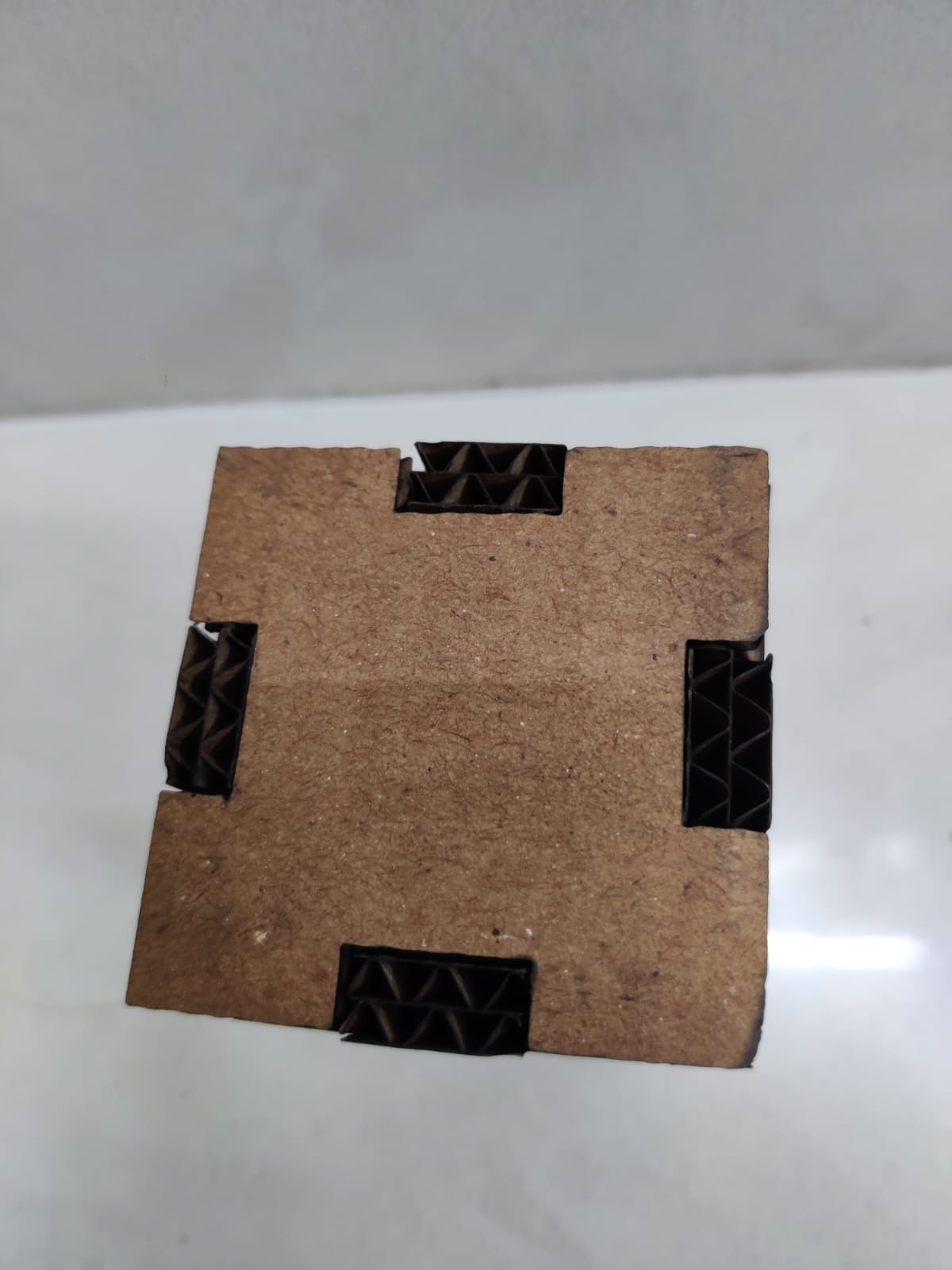
After cutting the file looks like this
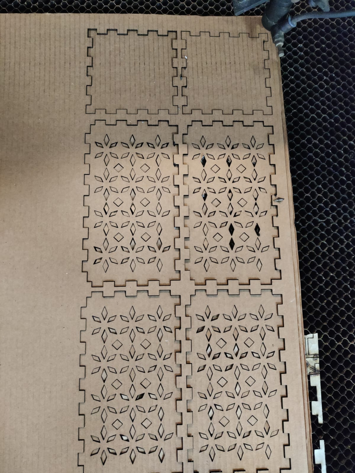
Step 2i Initial Outcome
Step 3: Kerf test cut
For the testing of the fitting between two finger joints , I first experimented by just printing the small size finger joint boxes of varying thickness with different sizes as shown below:
The best fit dimension for a tight fit of approximately 7.3mm thick 5 ply corrugated sheet was 6.9 mm width. So we can estimate that the kerf is around 0.2mm for the laser cutter at riidl. If wondering how it was calculated, then
[Thickness (7.3mm) - tight fit dimension (6.9mm)]/2 = Kerf (0.2mm)
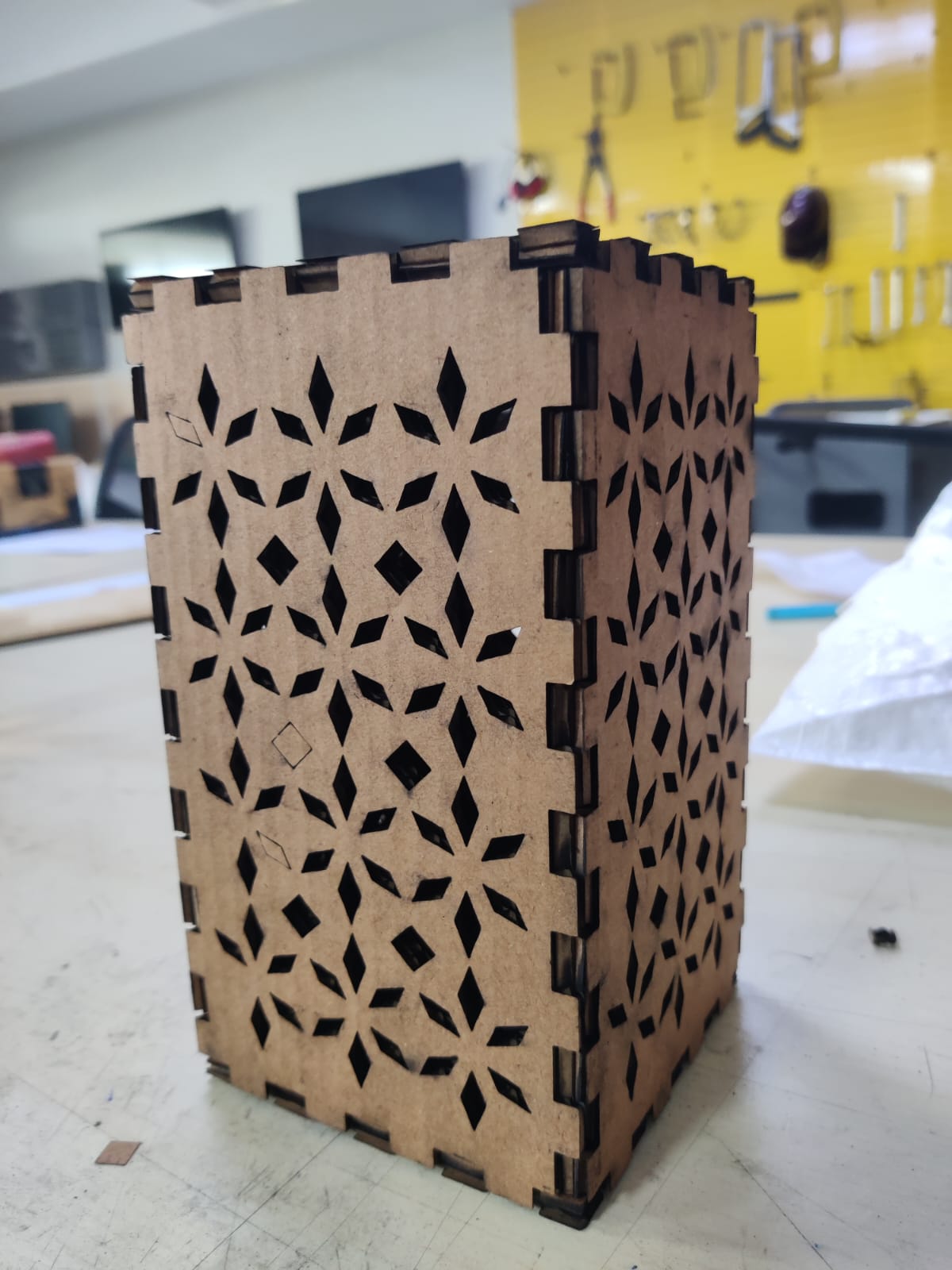
Step 4: Cutting everything and assembly
So after cutting all the pieces, it's time to build a lamp out of it. The thinking behind the design was to be able to achieve a closed lamp like structure by connecting with H finger joints. After multiple try and error I got a perfect fit. !
Hero Shots
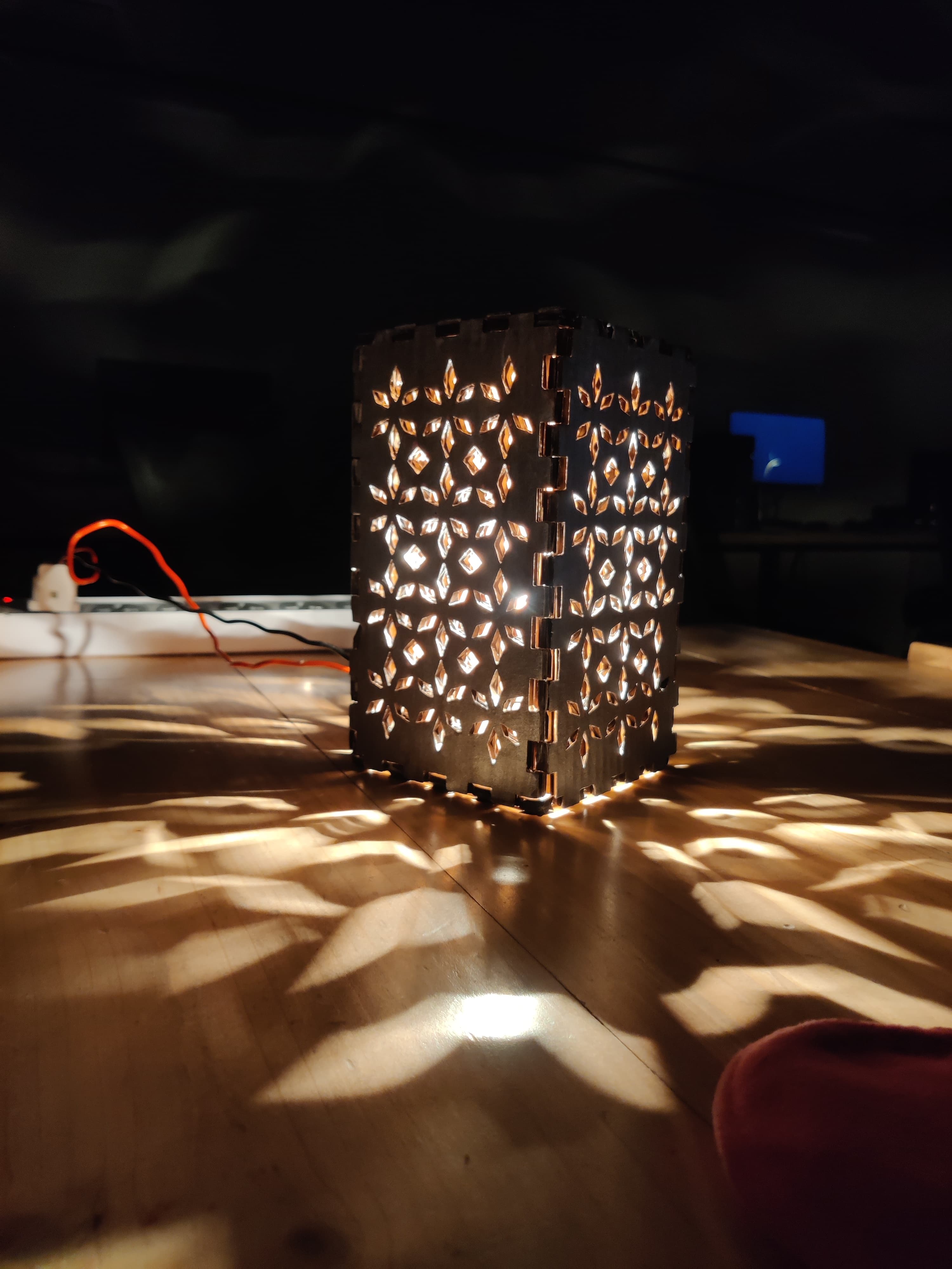
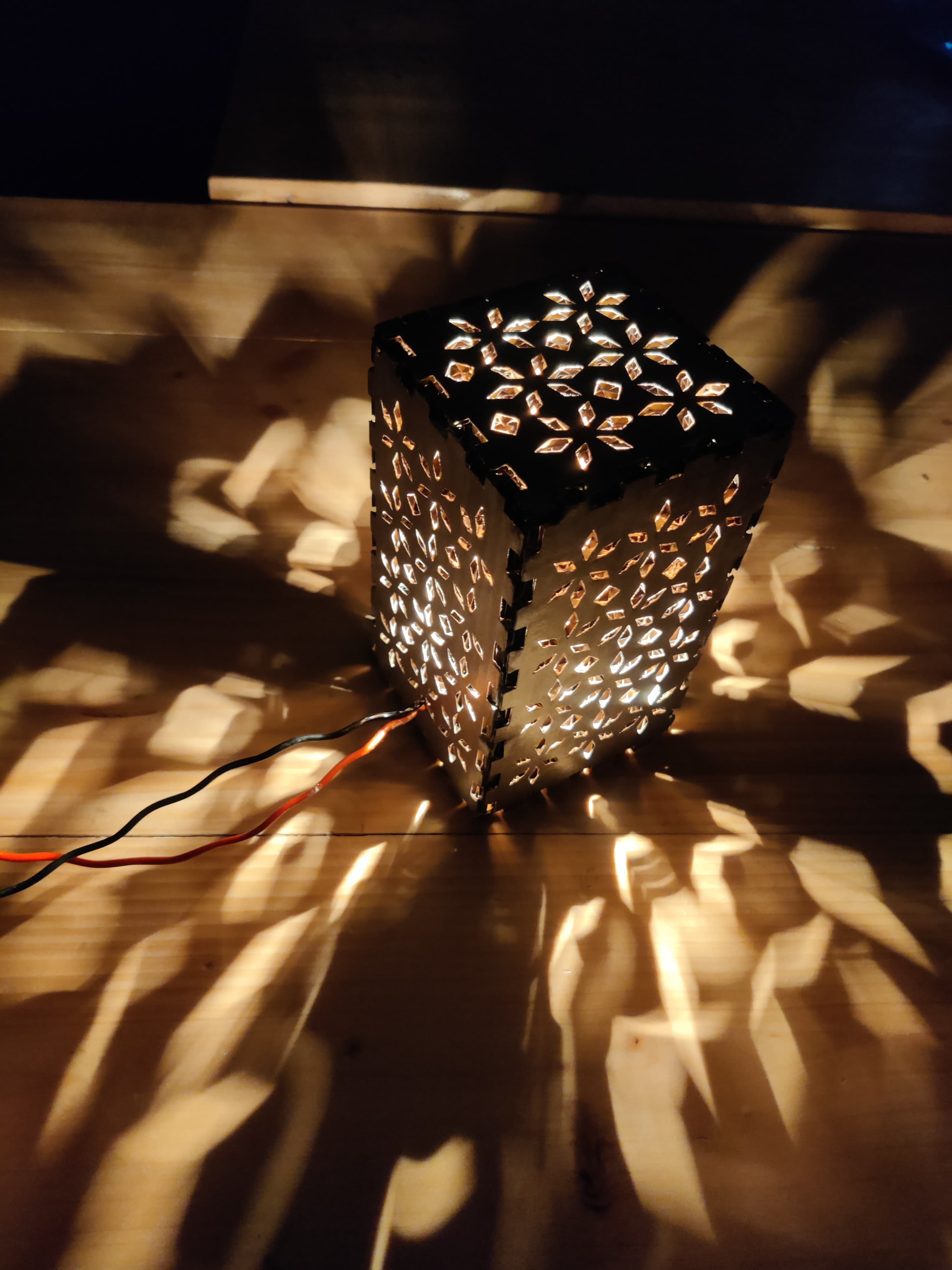
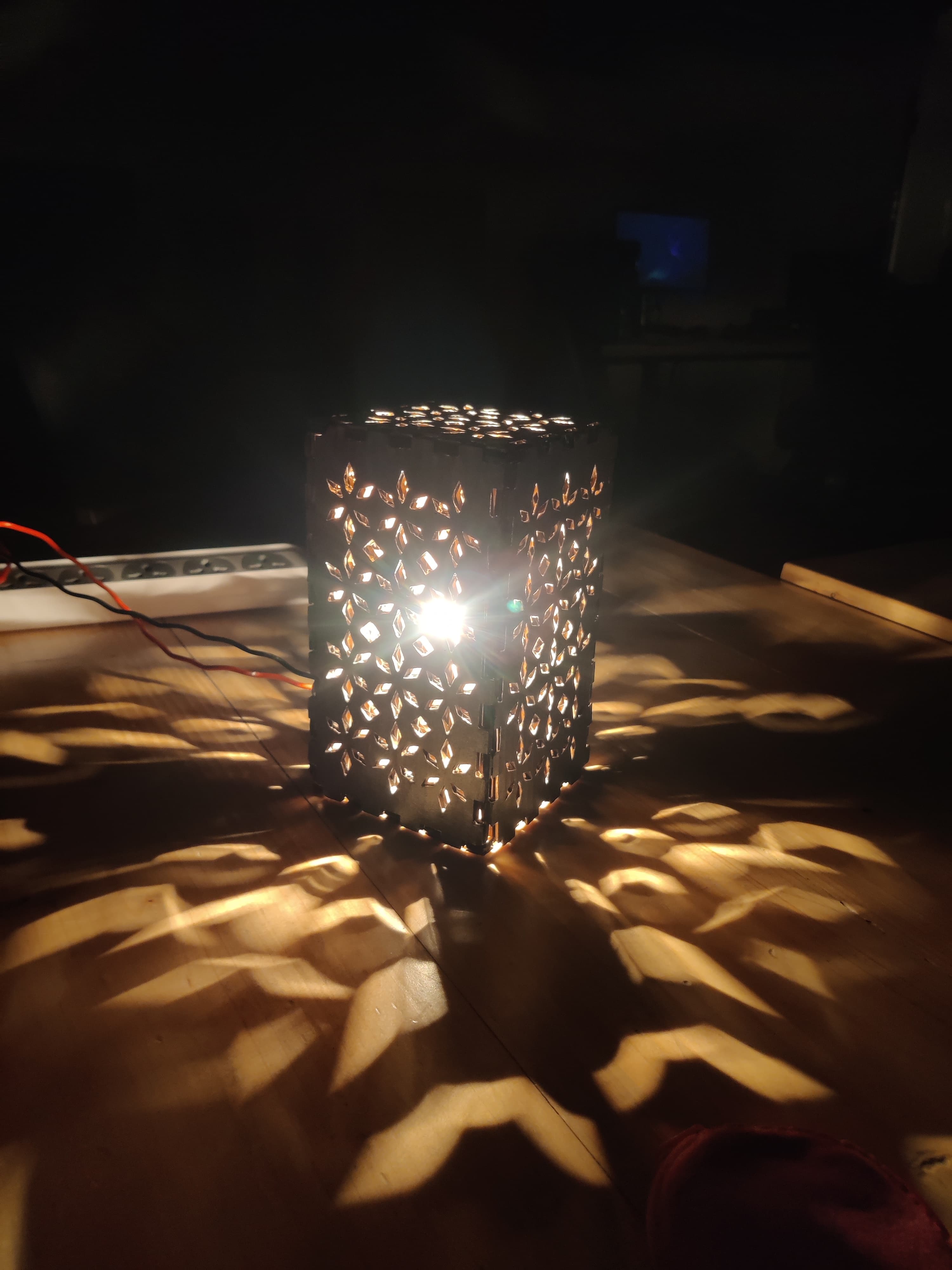
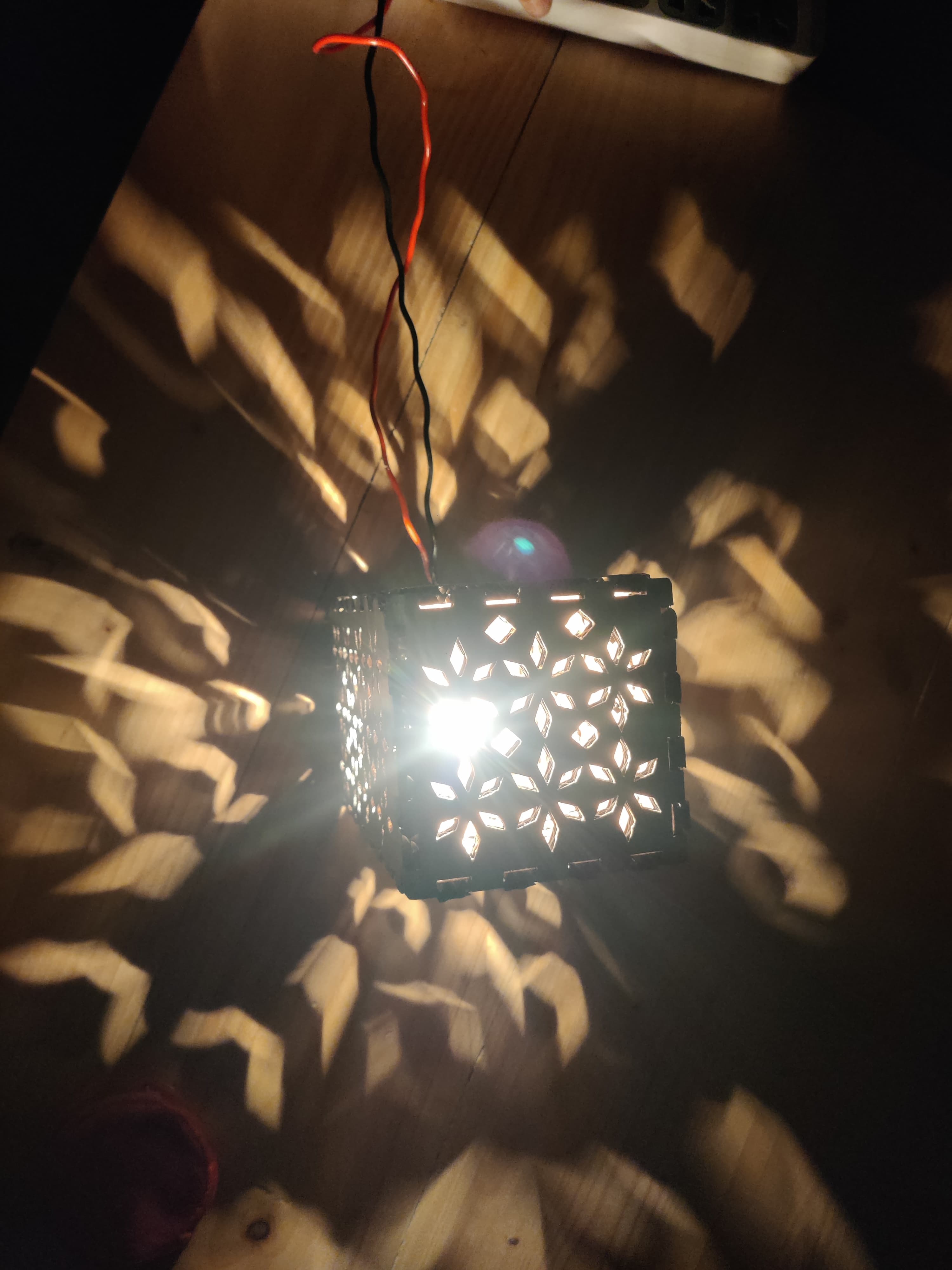
Lamp Effect
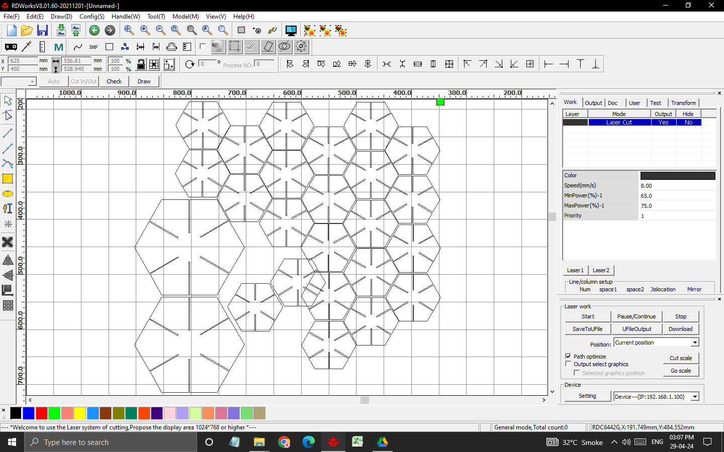
Parametric Design Kit 2 After doing the lamp my mentors told me to explore more as it was a very basic parametric, so I though I'll make a holder with 2mm ply which can hold anything and can be used on the side of bed or may be study table. I started designing the file on illustrator as shown below
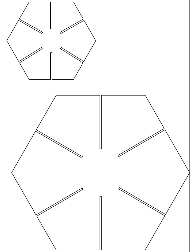
As I designed my file on illustrator for this thing it worked as I knew the kerf of my machine as we tested the kerf of slot in the group assignment, the link of group assignment is here. To change even a 1mm measurement I realised I need to keep changing manually so I decided from next time I will make file in any 3d software for me it is fusion 360 as we can link the edge points with each other and if we change 1 distance of any point it automatically changes for all the other points.
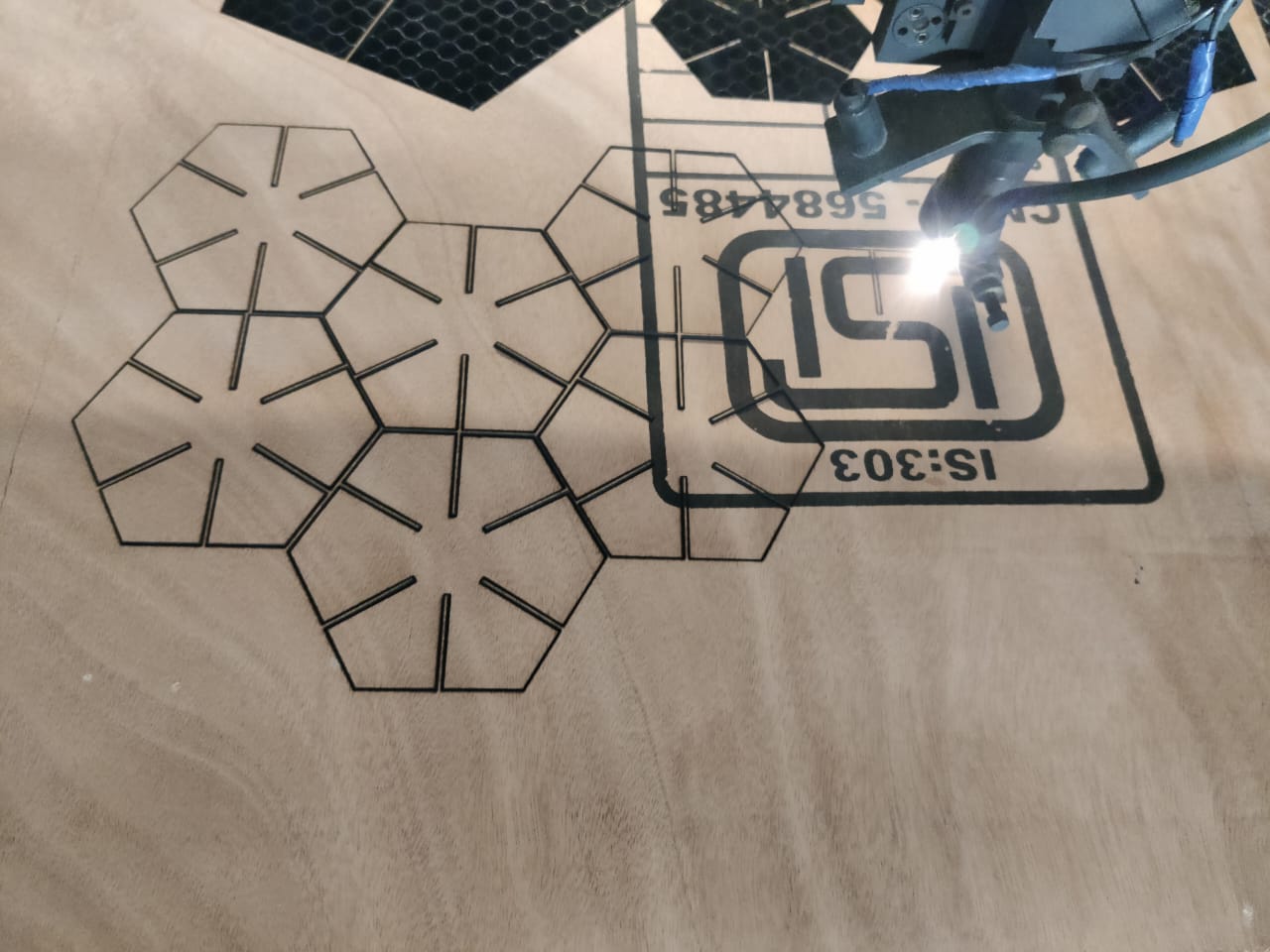
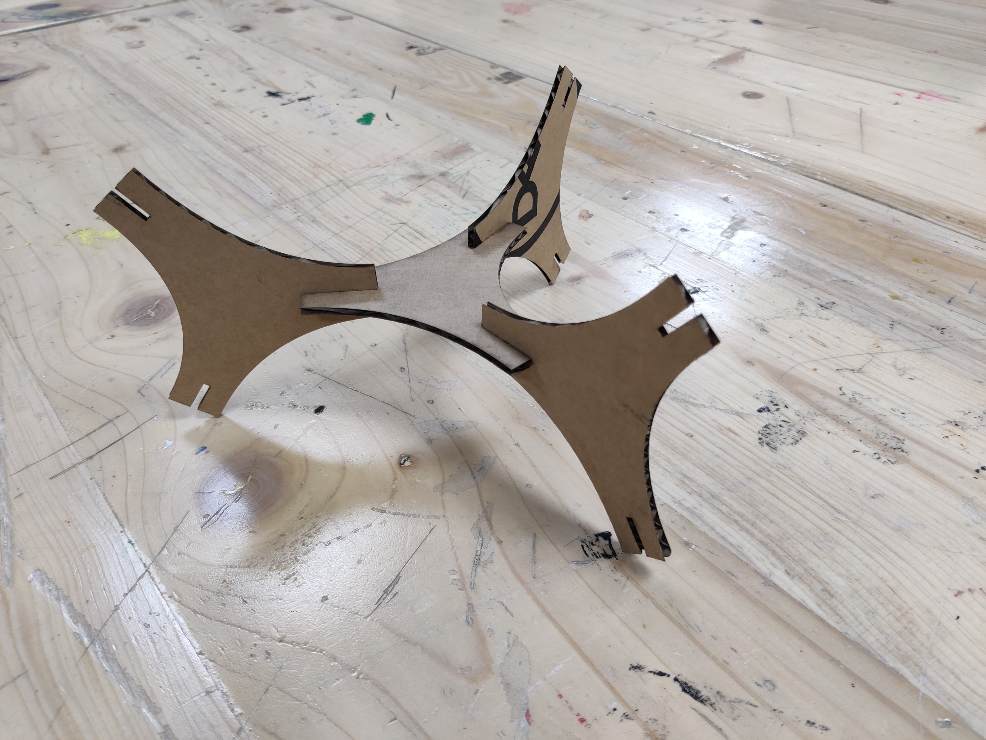
I cutted 1 big piece for the base and other 3 piece first and did the testing as shown in the picture below:
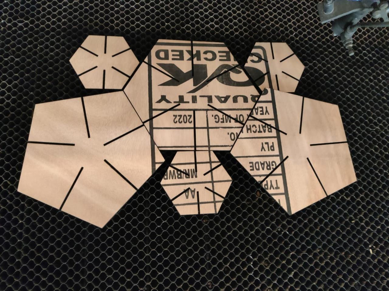
As it was fitting perfectly I started cutting all the other pieces after doing nestling for saving the material.The speed power for this material I took 4mm MDF speed power as mentioned below
To see the video of cutting the pieces Click here
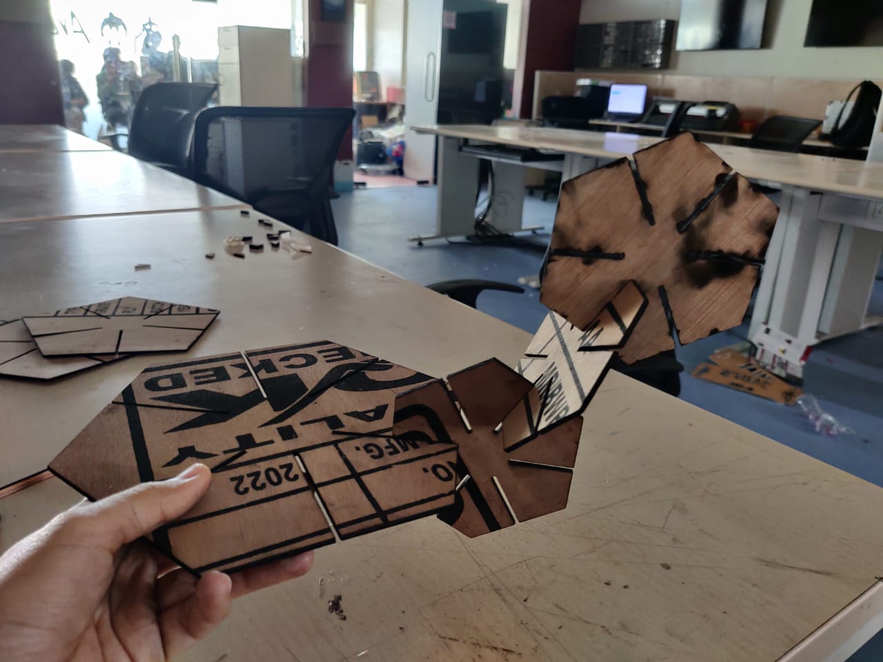
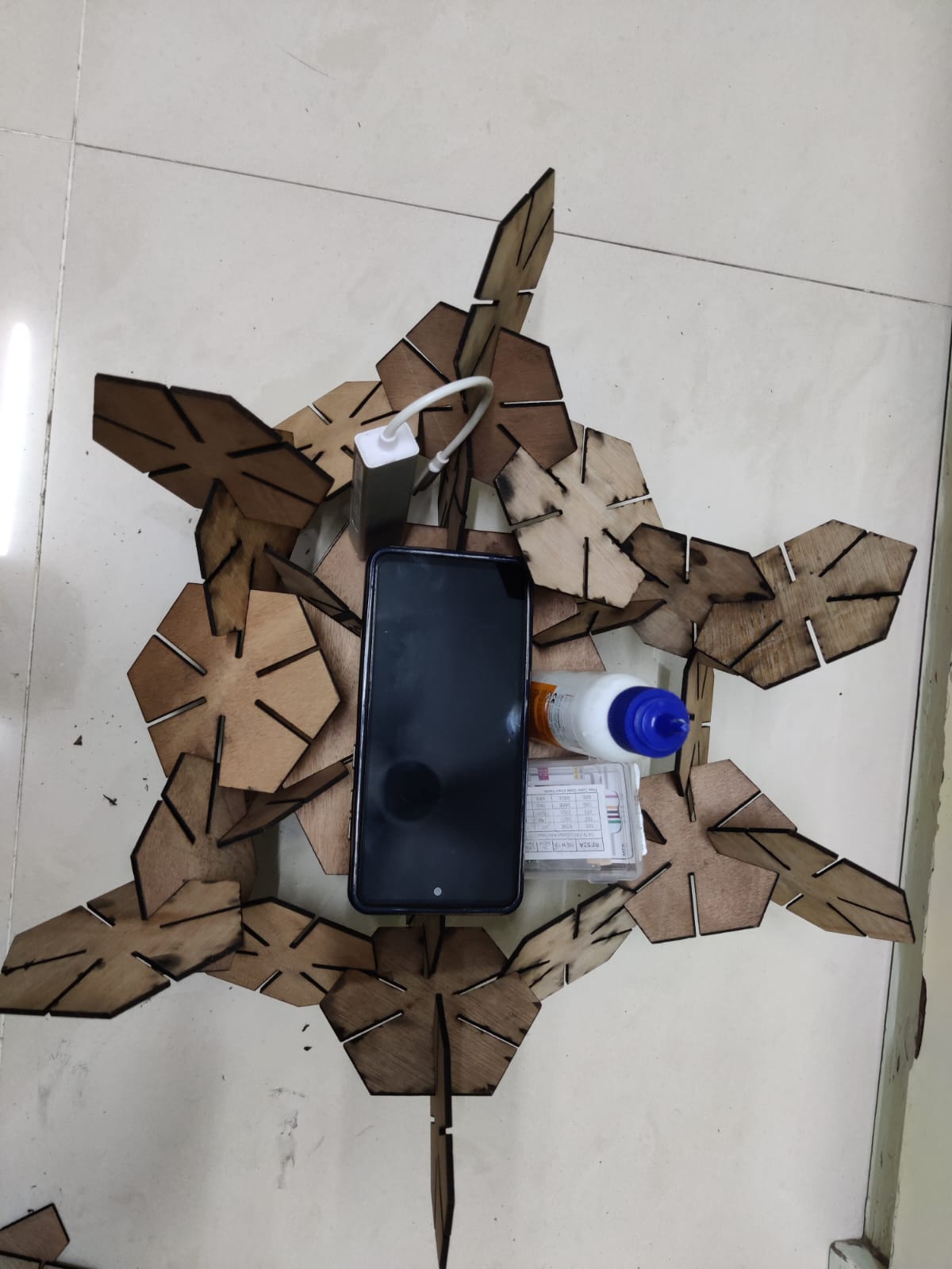
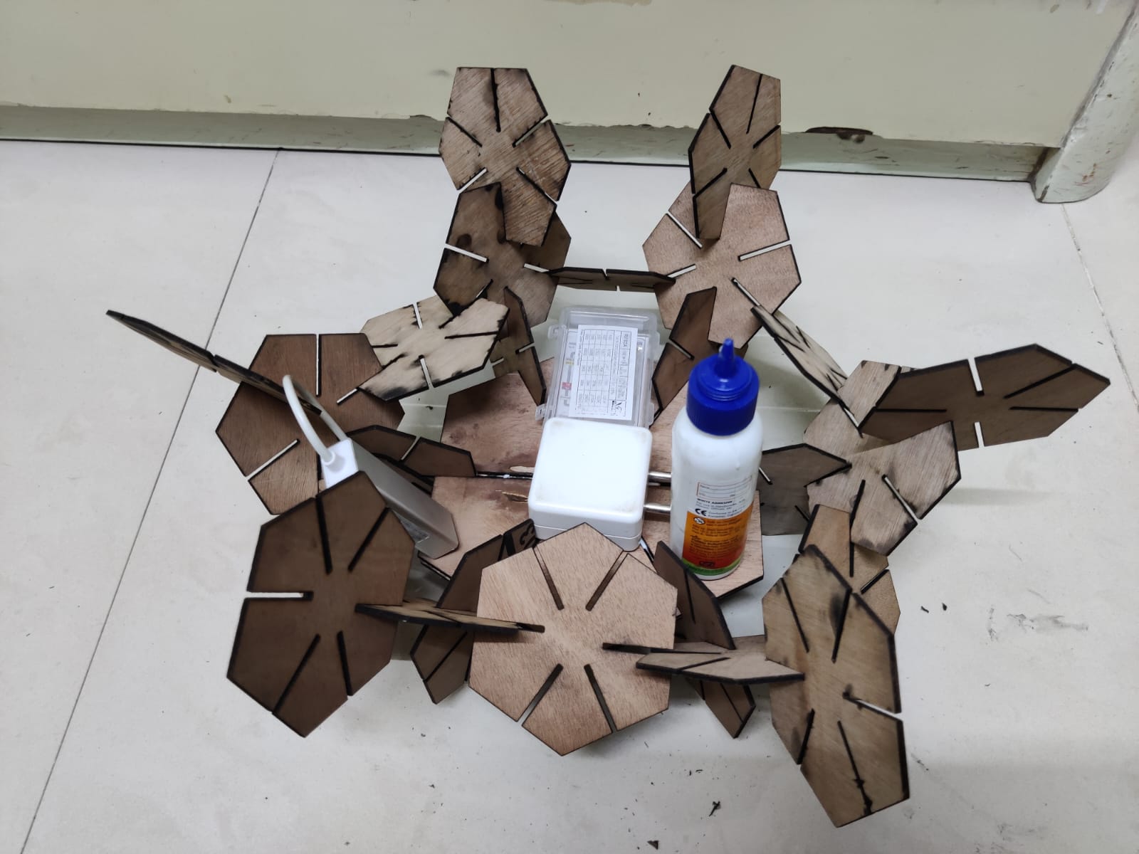
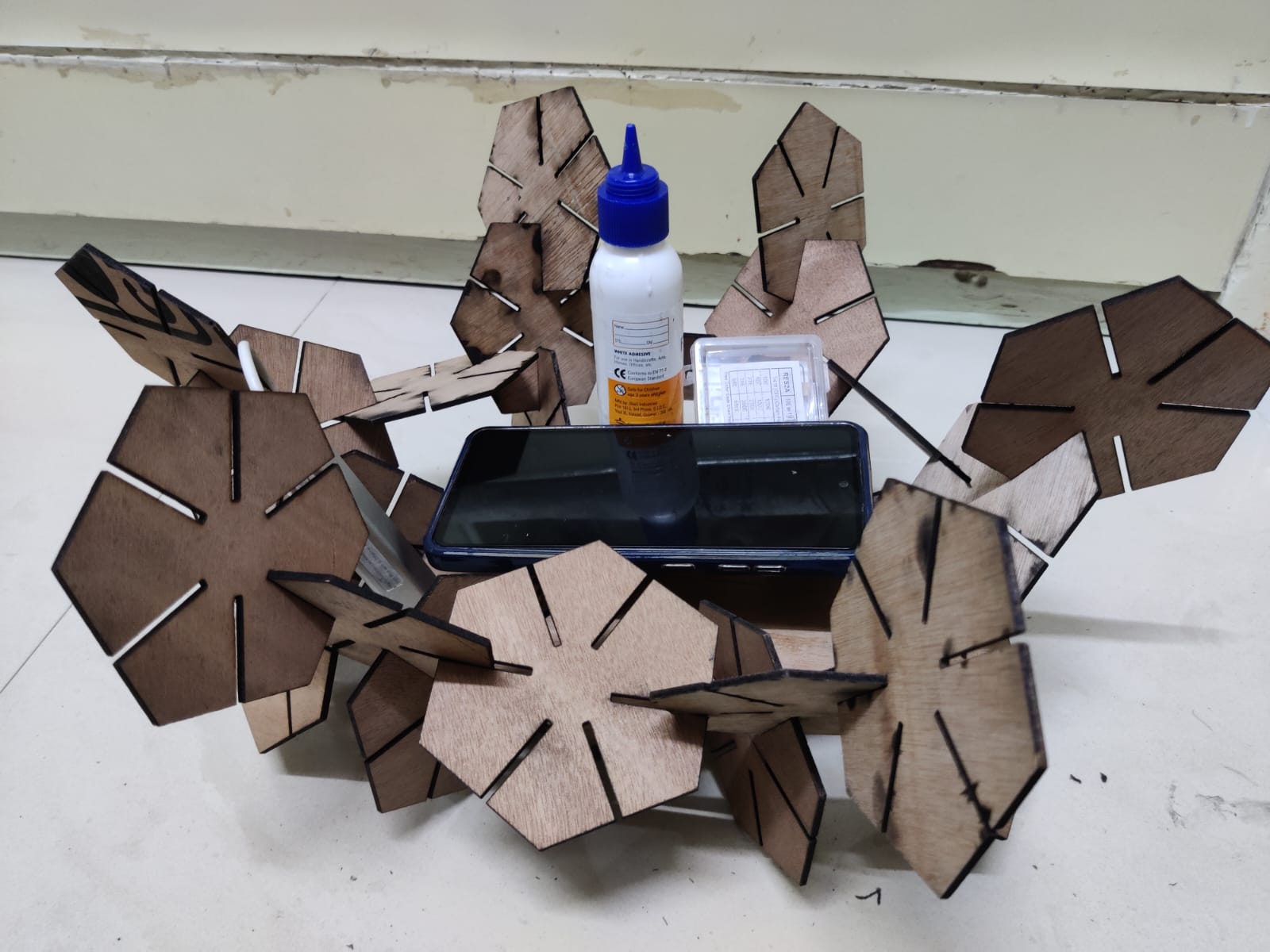
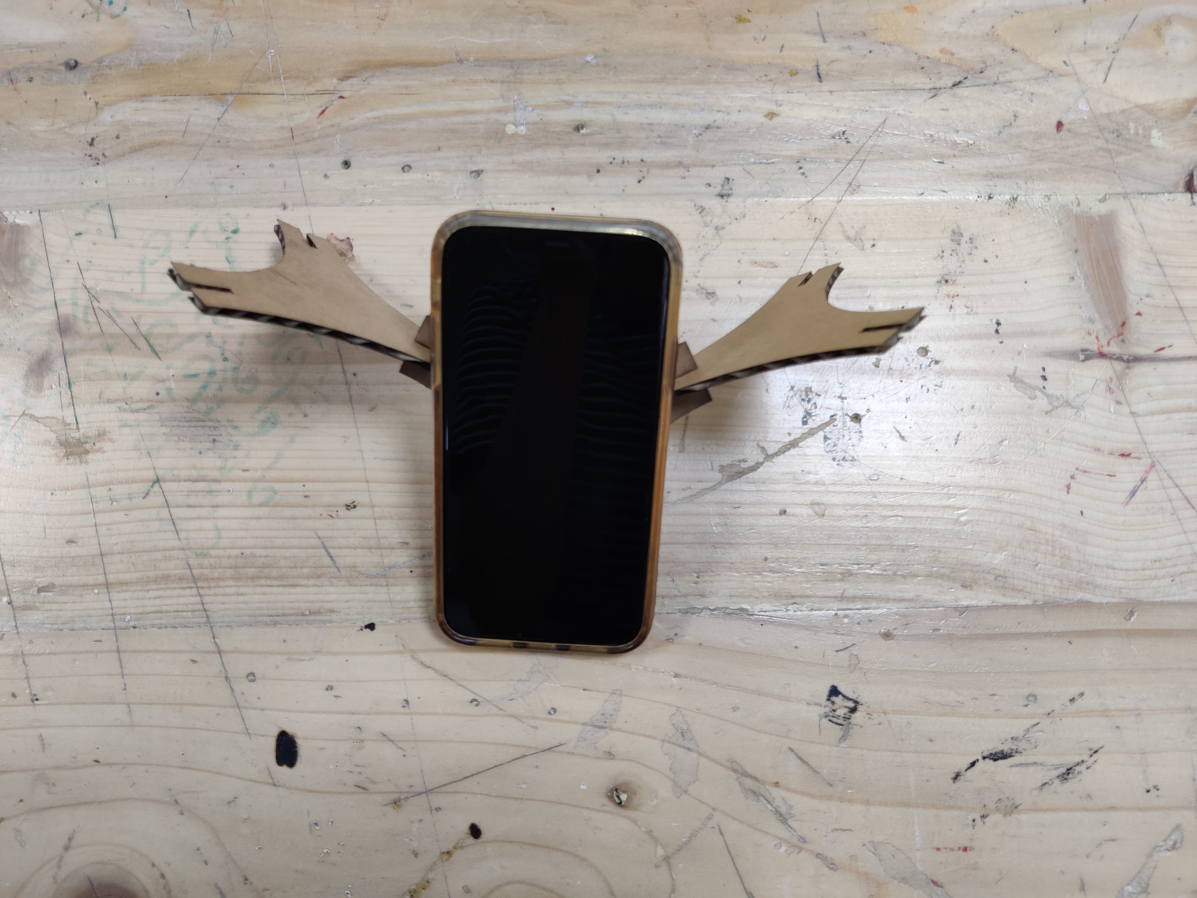
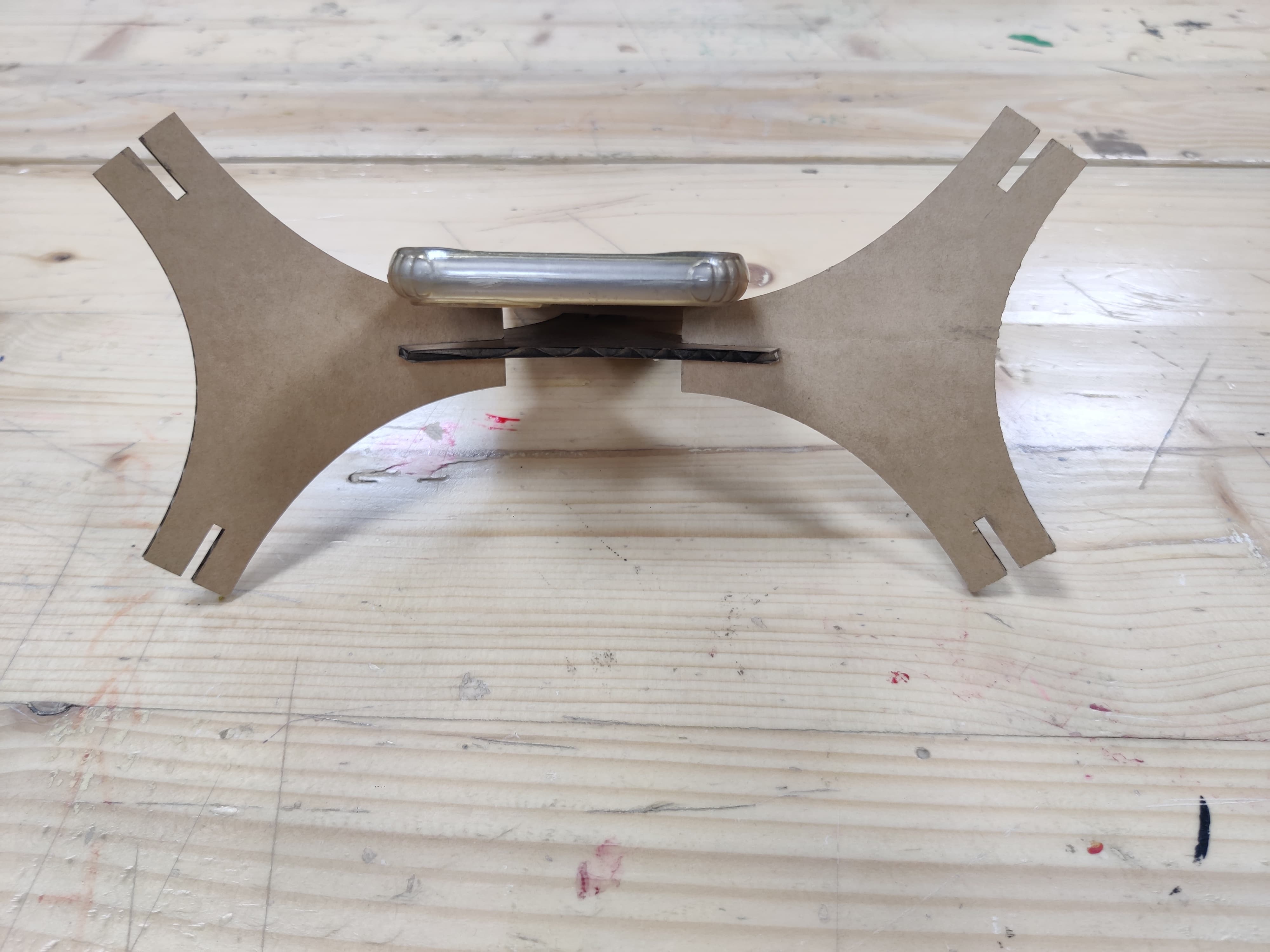
After cutting all 20 parts as my ply was 2mm and it was very thin and as it was a holder, the main weight was in the center so I made 2 big pieces and stuck it together.
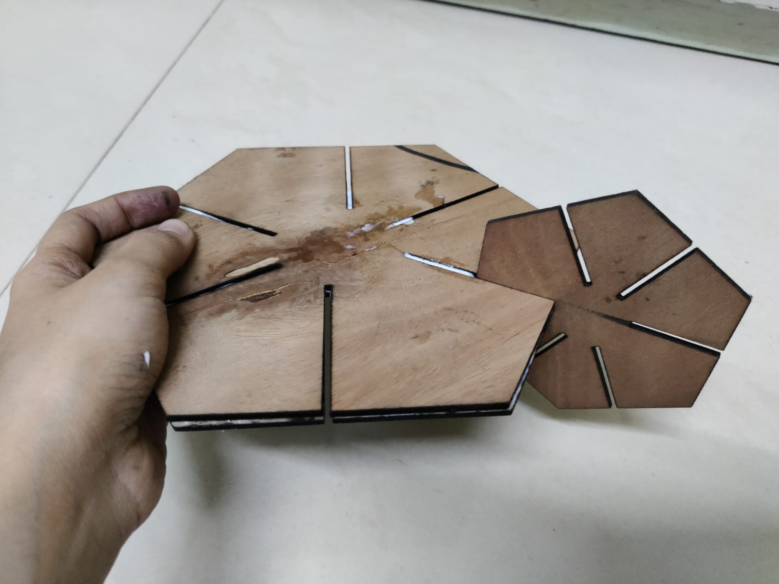
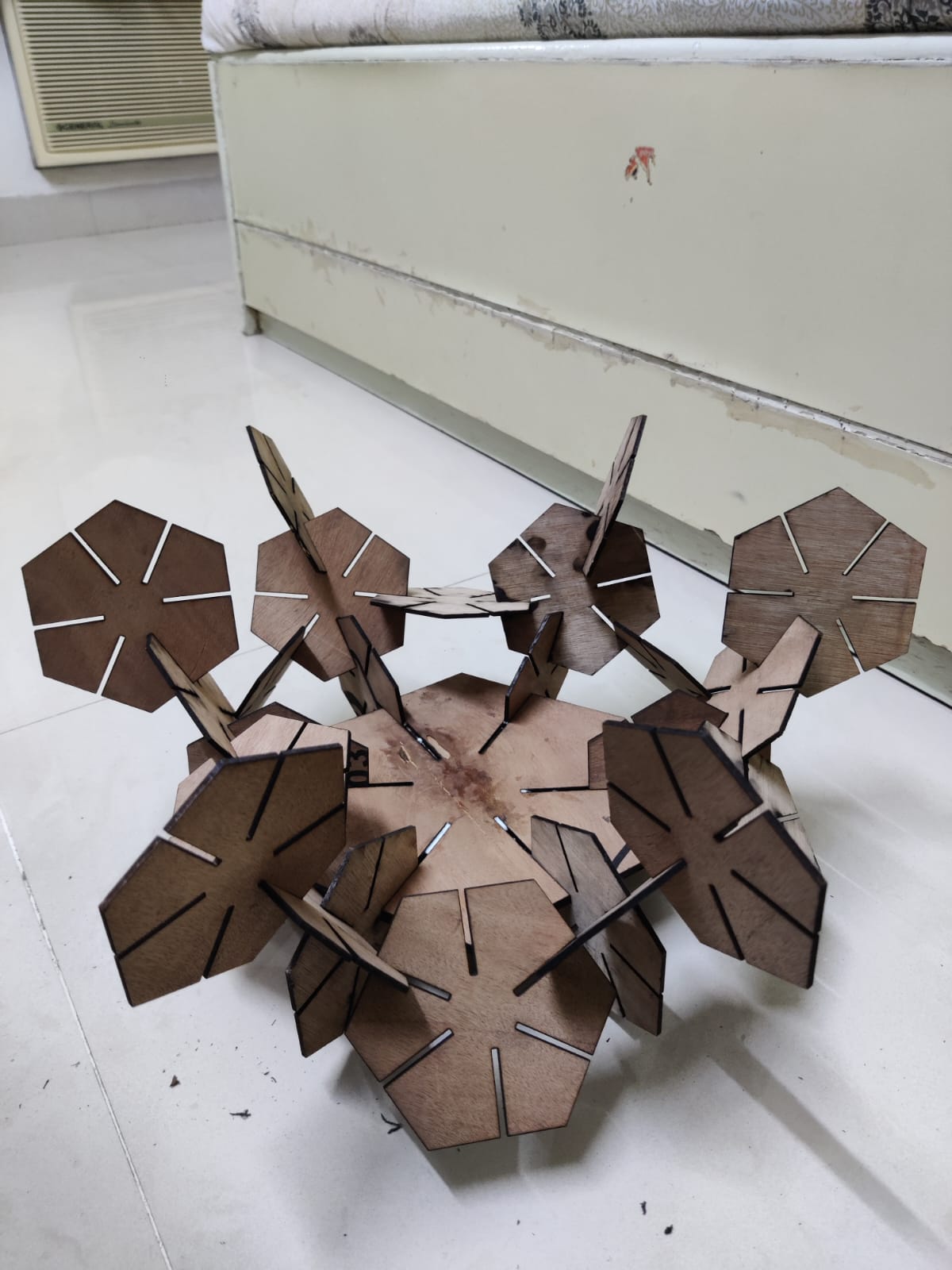
I started making the holder by adding more hexagons in the slots.
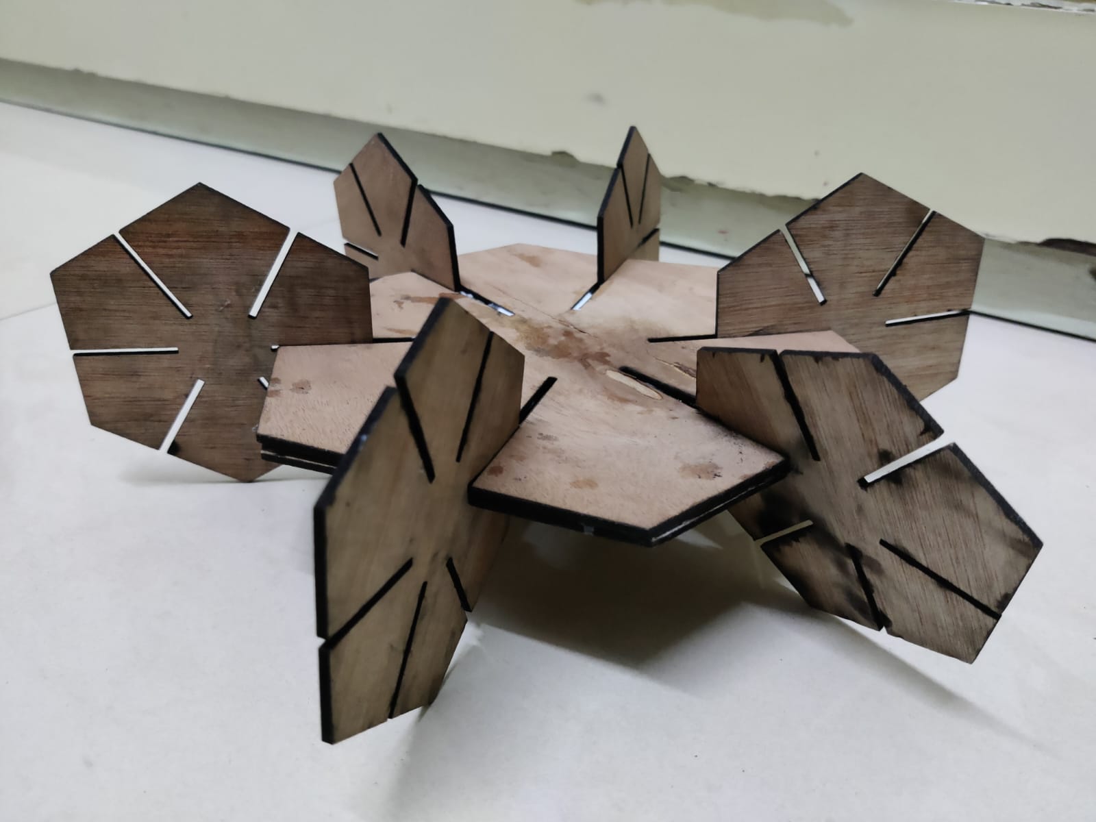
And here is the final outcome.!
Hero Shots
Error
After doing the above thing i got the feedback and I realised that I did the parametric assignment in the wrong manner, so i did it again.
Parametric design involves defining a system with a single parameter that can be easily modified, while ensuring that the shape of the unit remains constant.
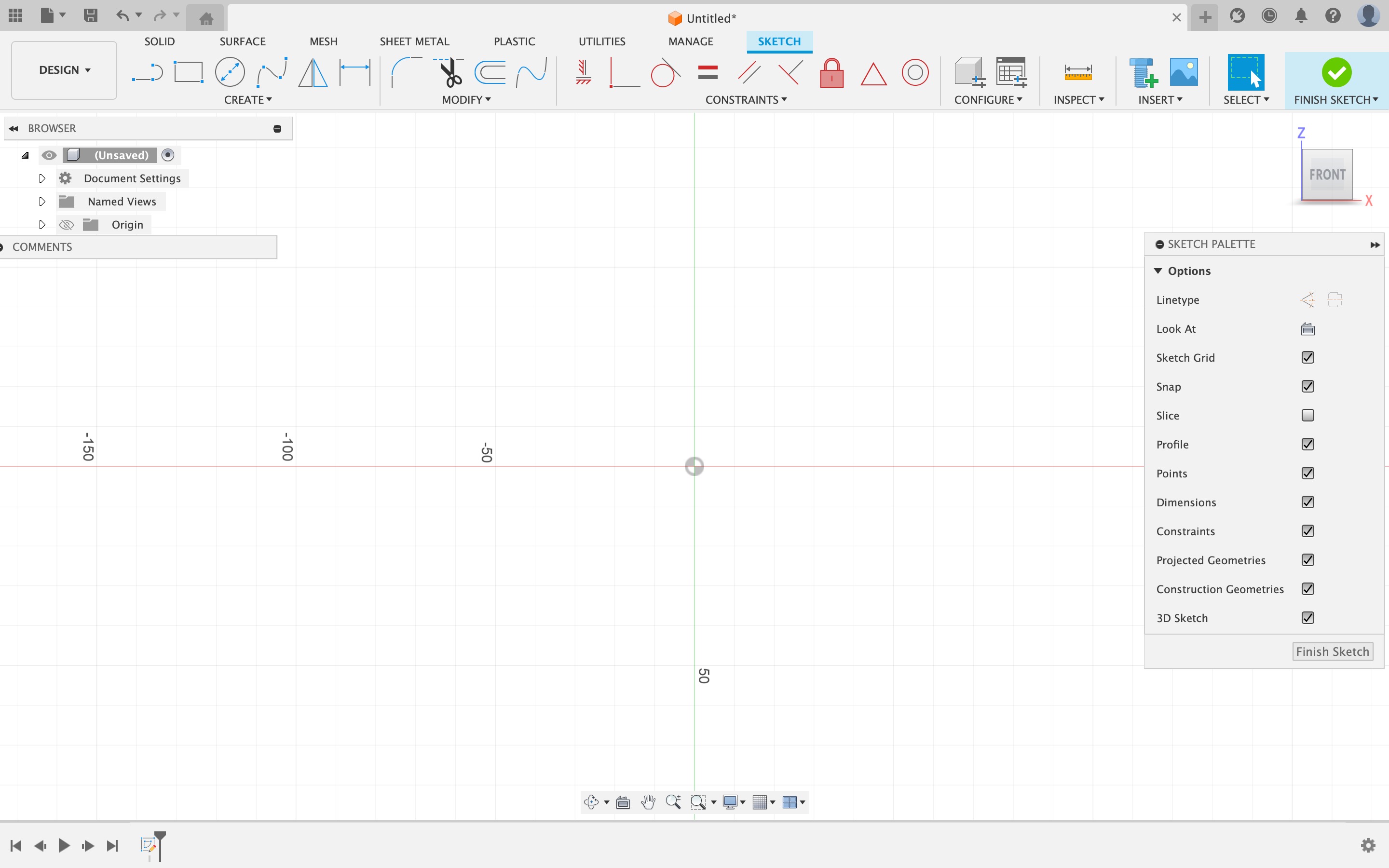
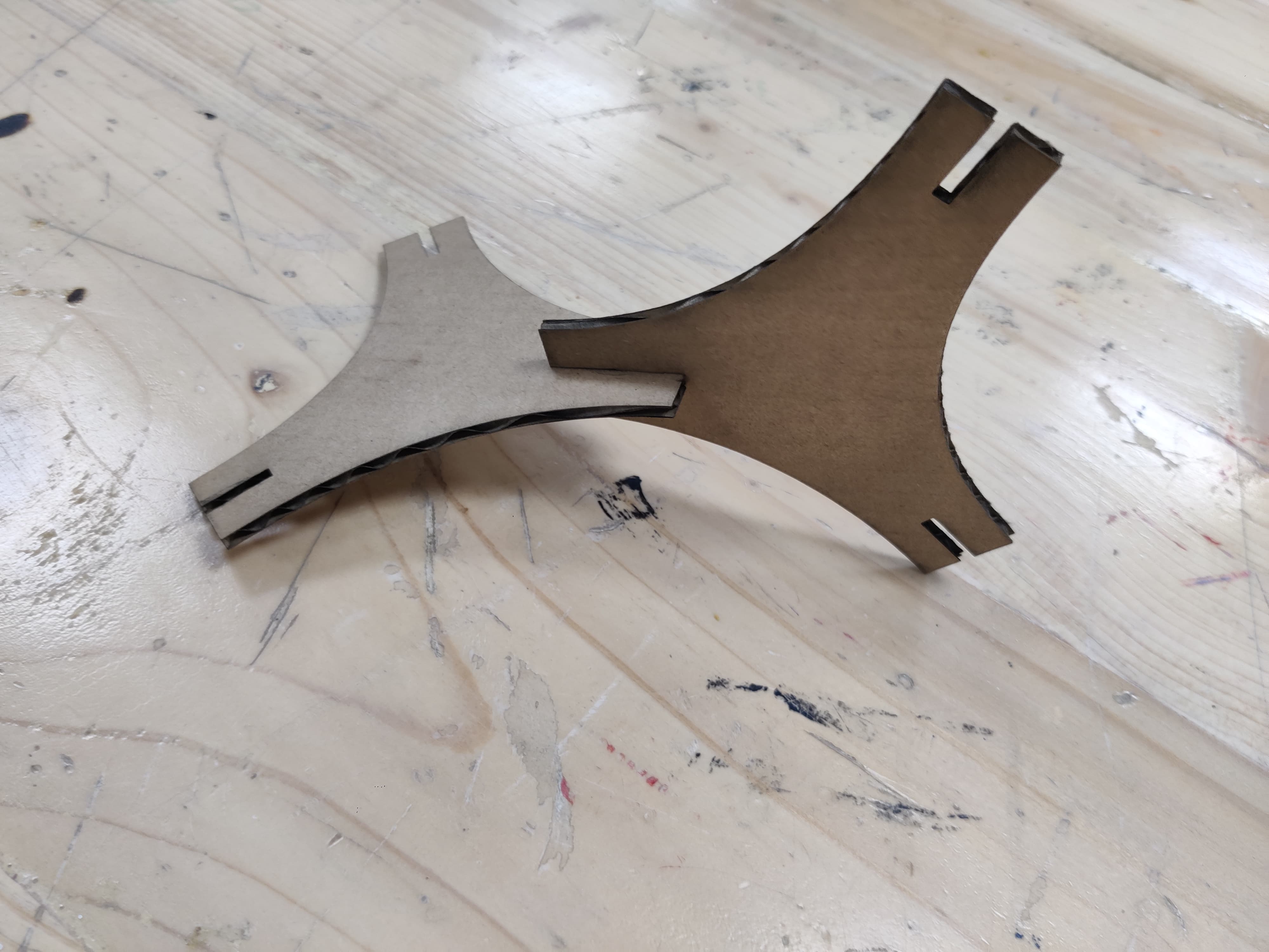
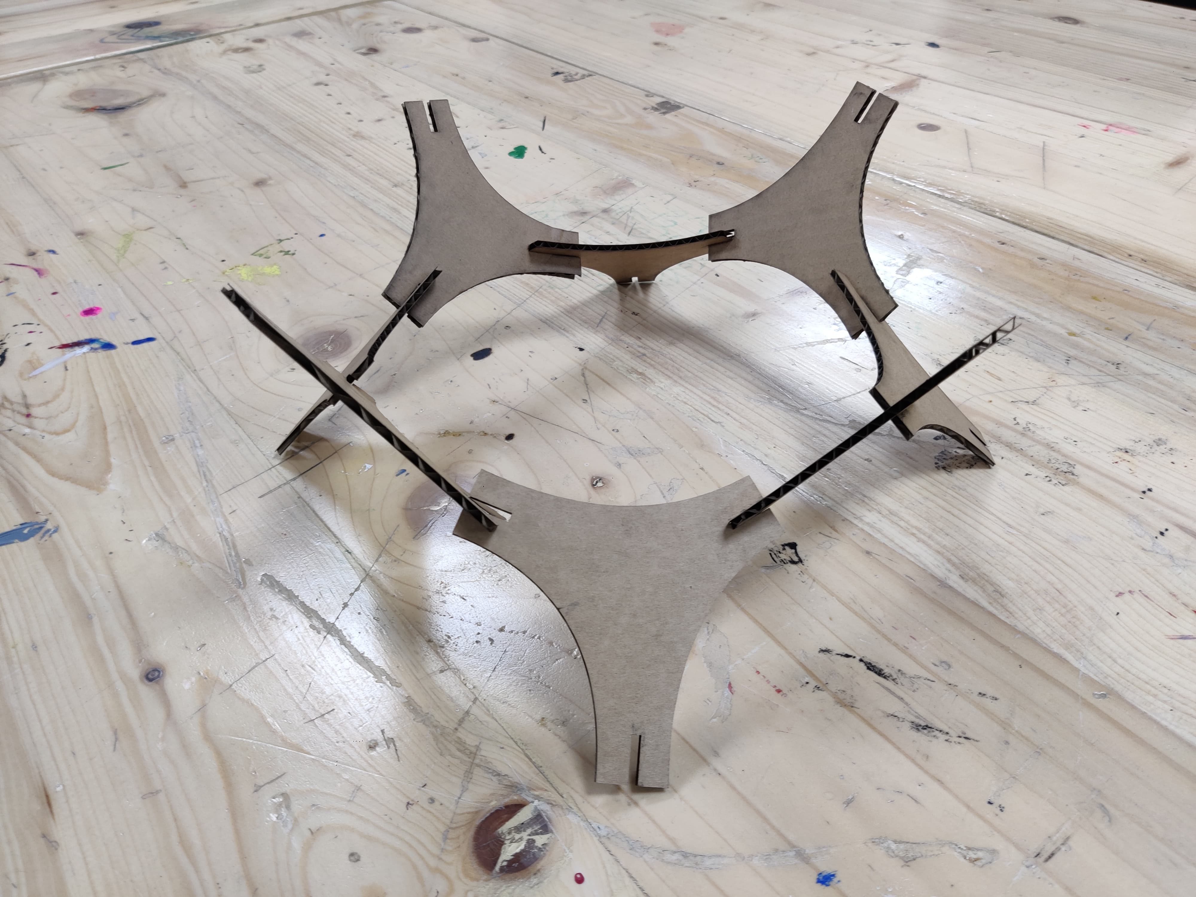
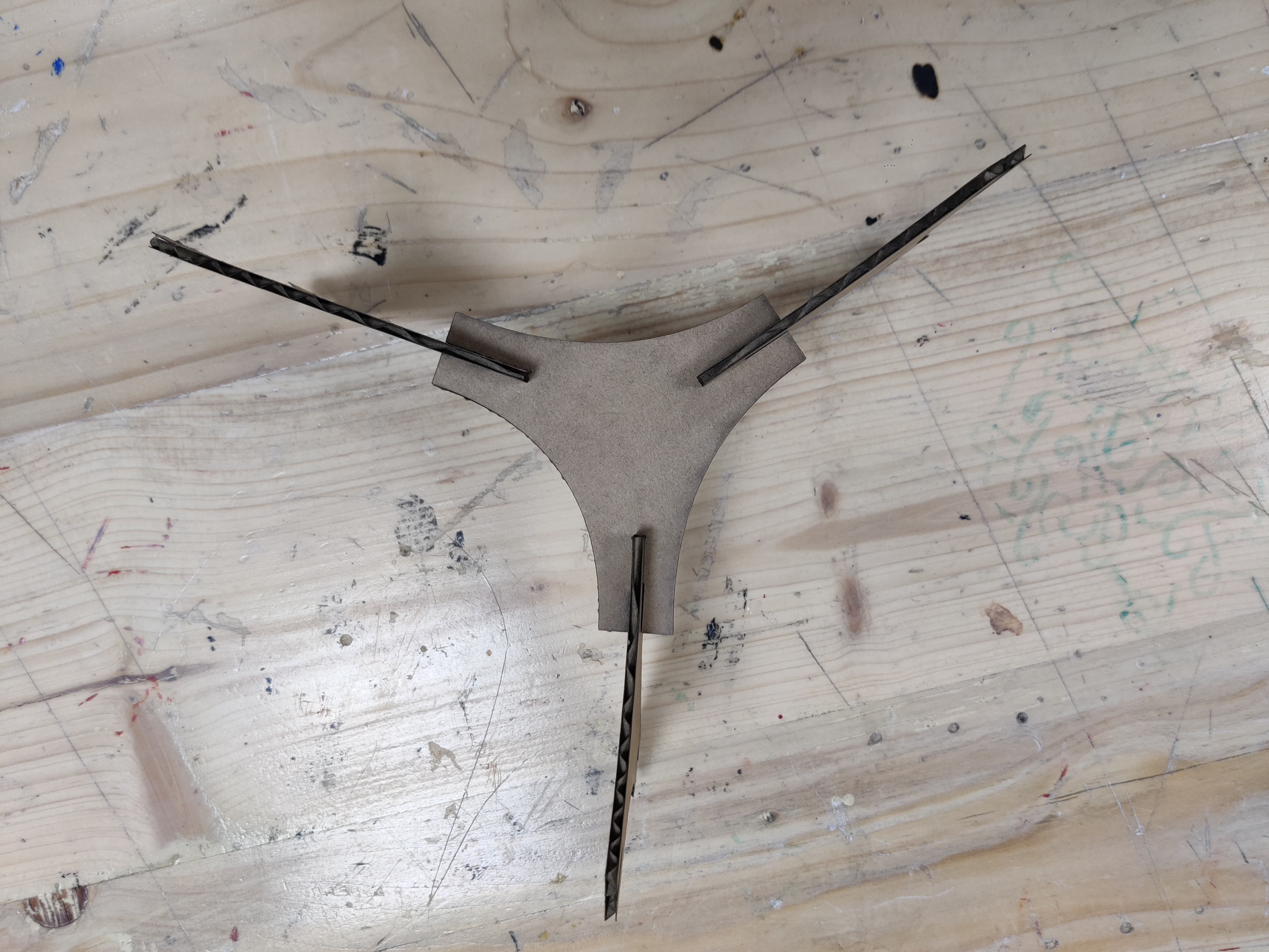
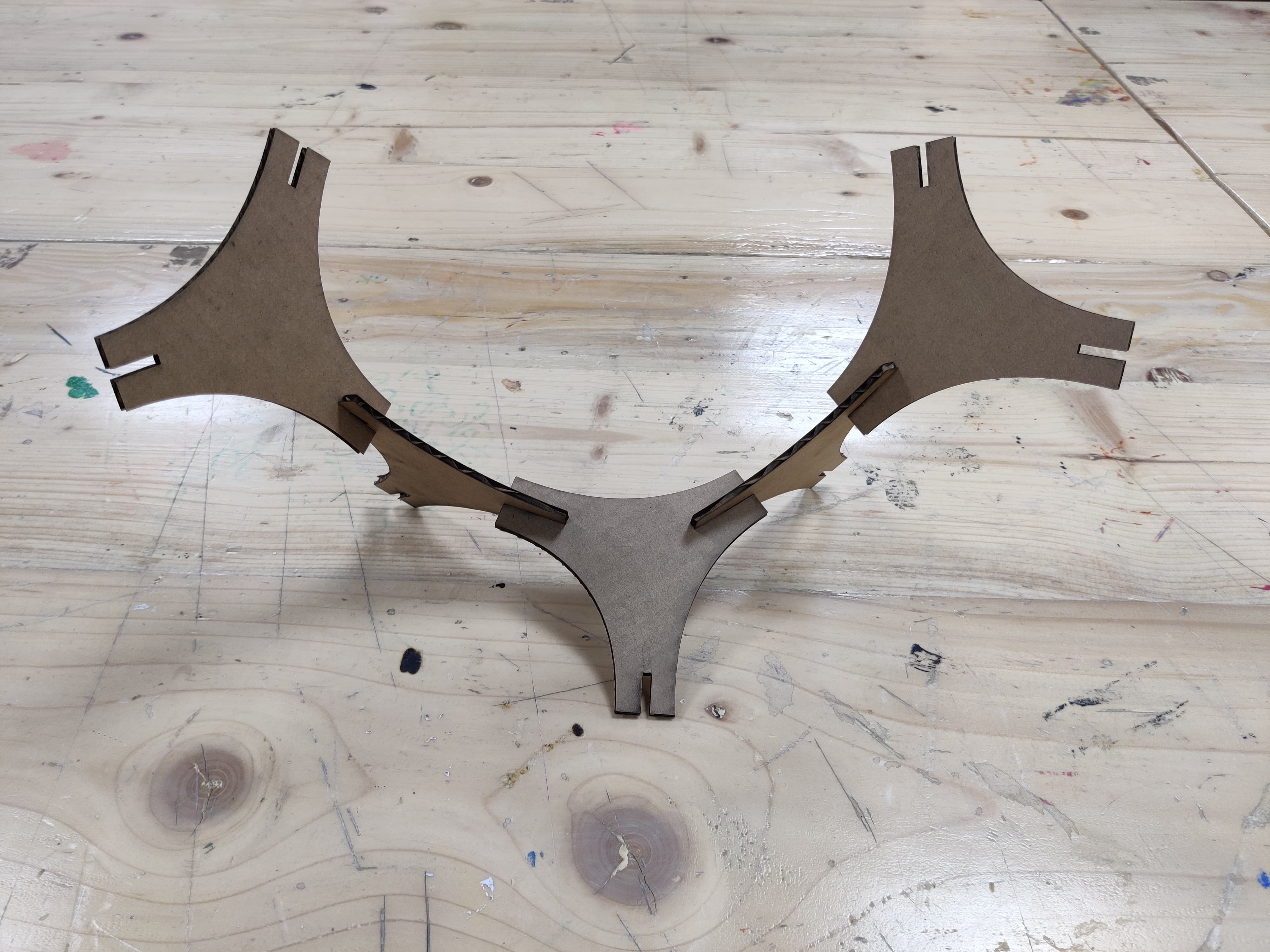
So now I chose a basic shape, I started with triangle and modified the shape with the help of curves, below is the sketch of the same
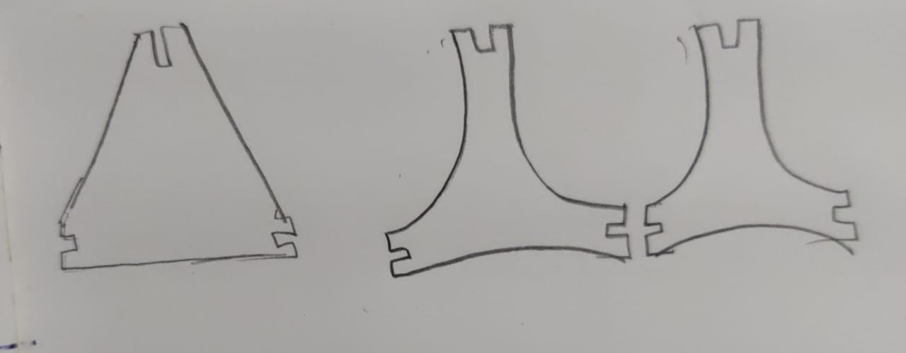
I created the sketch in Fusion and linked the slots so that modifying one would automatically change all. Then, I exported the DXF file and imported it into Illustrator for further adjustments in positioning. It was a realization for me that I could have done these modifications directly in Fusion, which was a valuable learning experience. After finalizing the design, I proceeded to prepare it for cutting.
Step 1- As usual, the process commenced with Design. I initiated a parametric design within Fusion 360, beginning with parameters setup in the software.
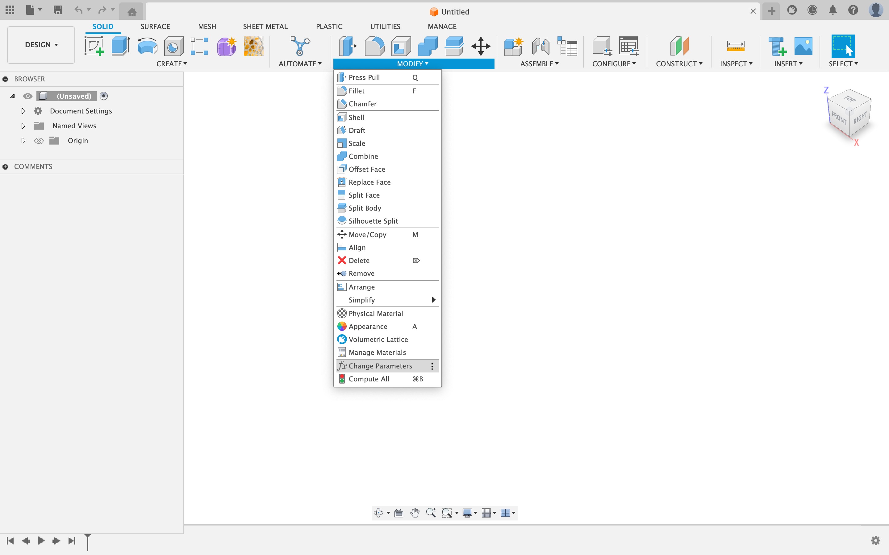
Step 2- Use the "Change Parameter" tool to add parameters.
In Fusion 360, parameters are adjustable attributes that enable automatic model updates upon modification. These attributes encompass dimensions, angles, tolerances, and other design constraints. Leveraging parameters facilitates seamless design modifications and enables exploration of diverse variations. Moreover, when employing Fusion 360 for computer-aided manufacturing (CAM), you can specify parameters governing toolpaths, machining strategies, cutting speeds, and feeds. These parameters dictate the execution of tooling and machining operations on your design.
I planned to use waste corrugated caedboard which was lying in waste pile, so I used it, it was dell computers cardboard which was 3mm. I gave the digital sketch an offset of 0.15 mm (half of the kerf value we found in the Group Assignment section).
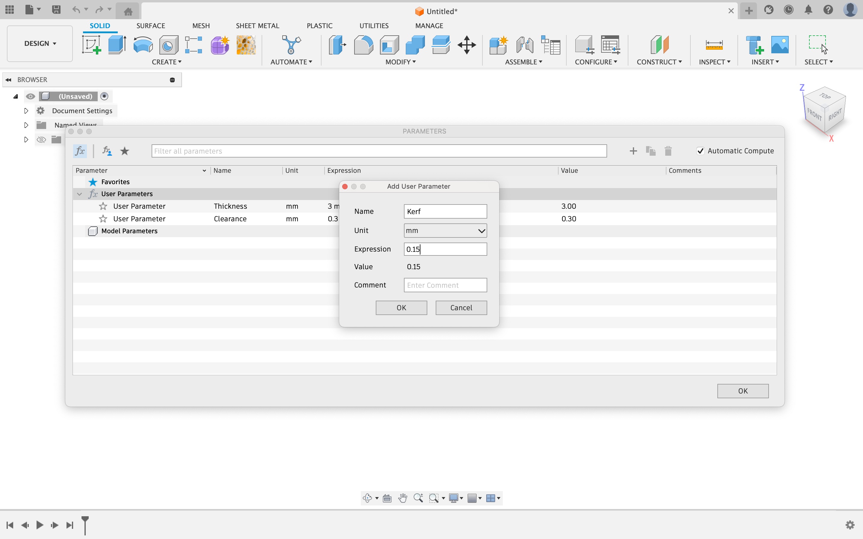
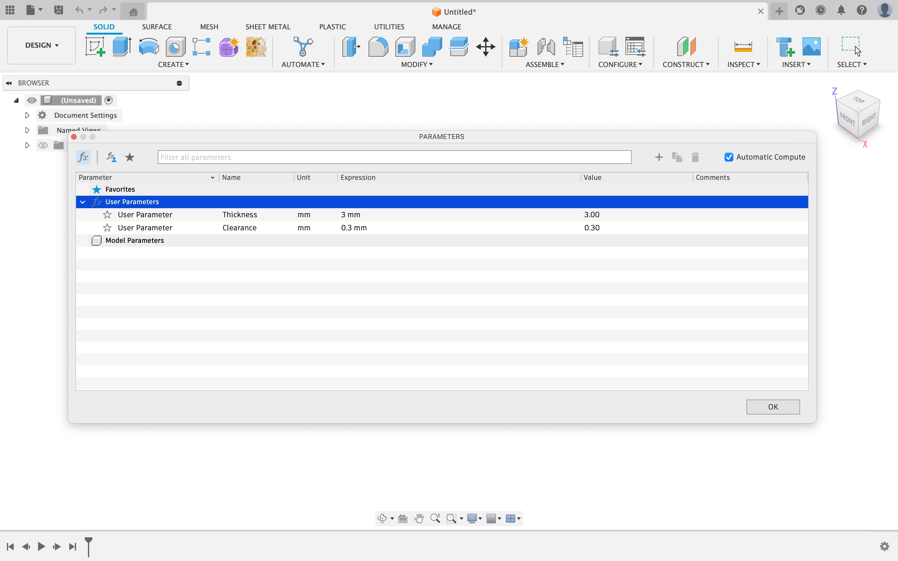
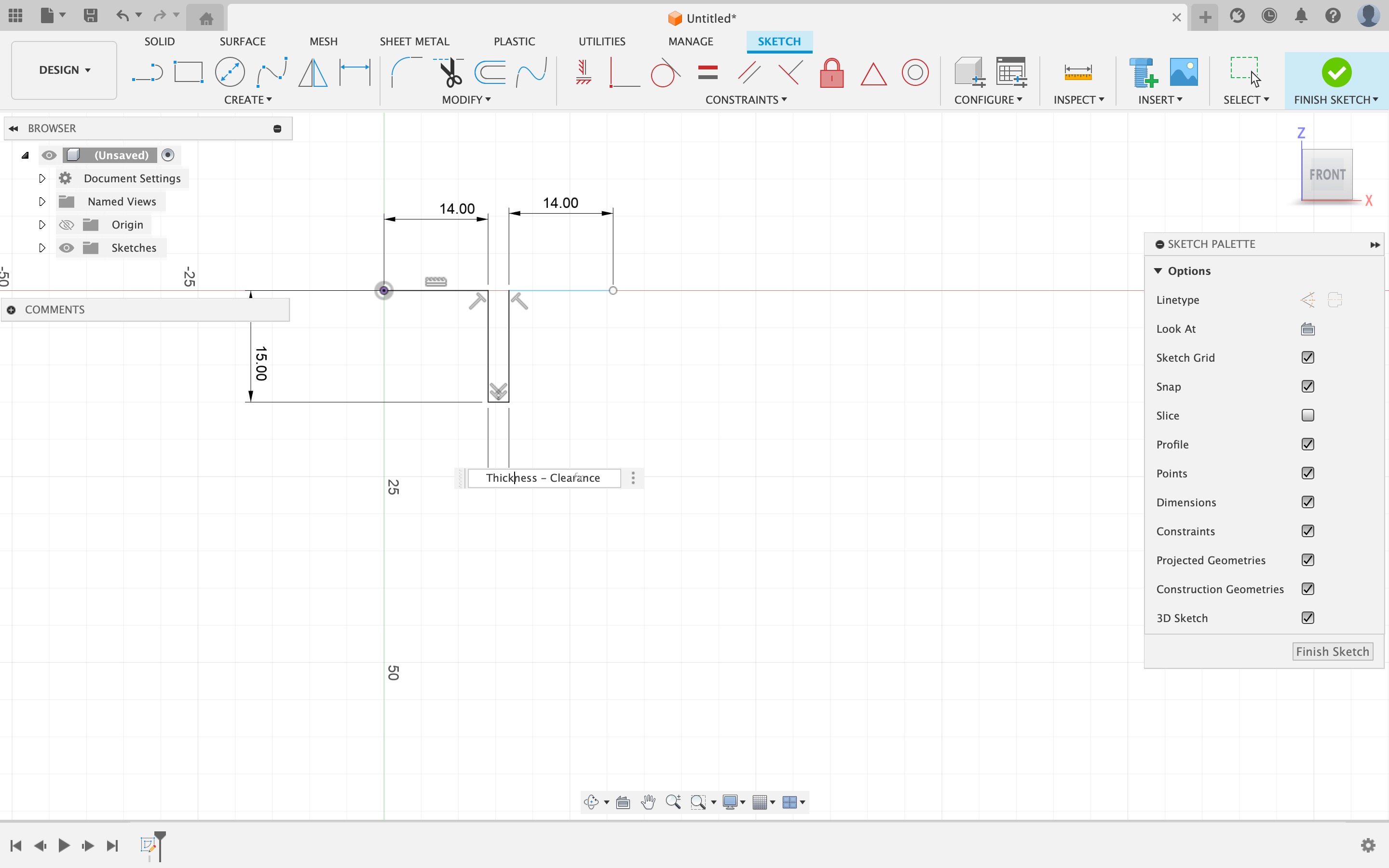
Step 3: Here are the parameters incorporated into my design: thickness, clearance, kerf, join clip gap, etc. These can be adjusted at any time without affecting the overall design.
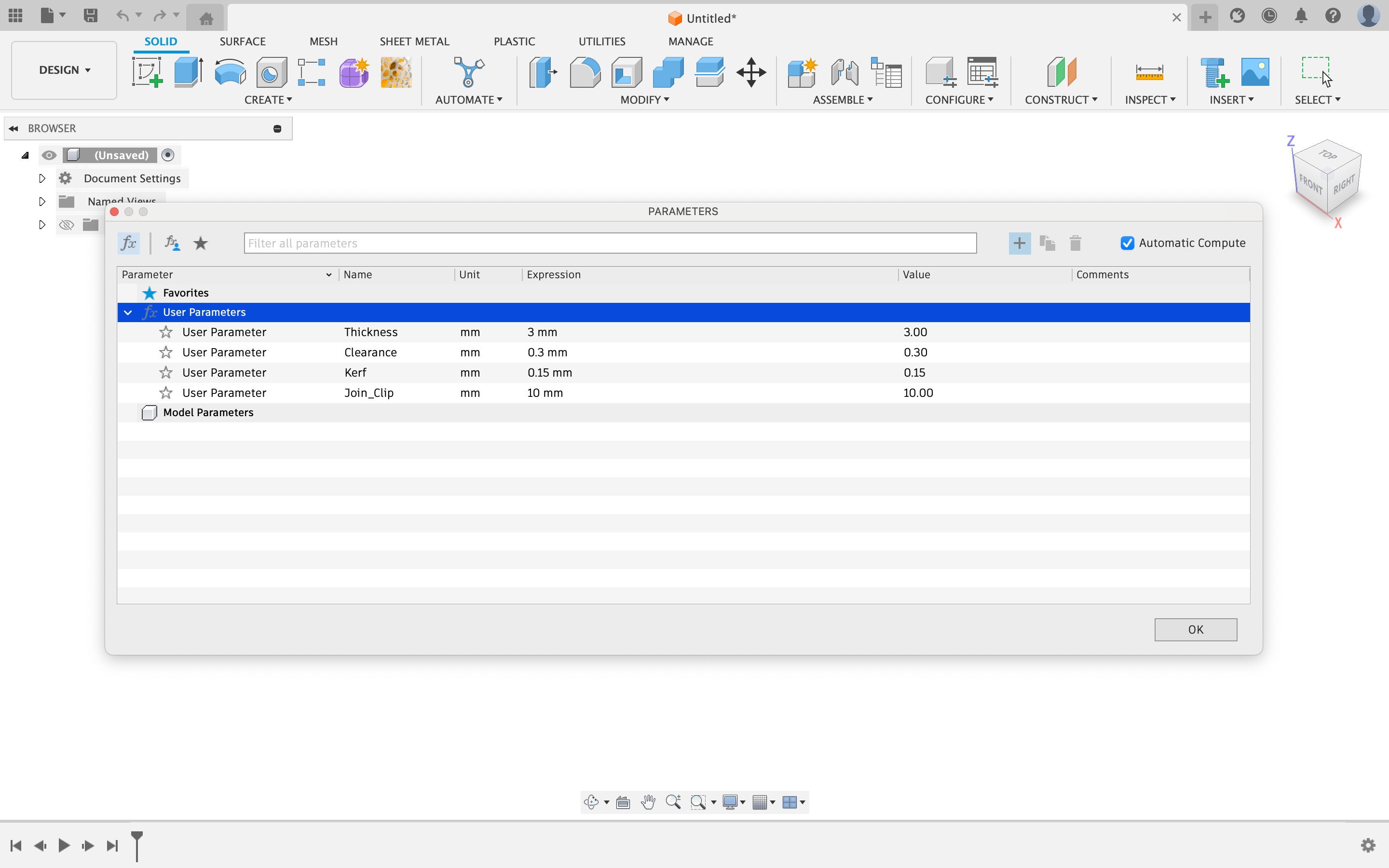
Step 4: Here's how I made connections with parameters in the design. Dimensions were created using formulas that linked each parameter.
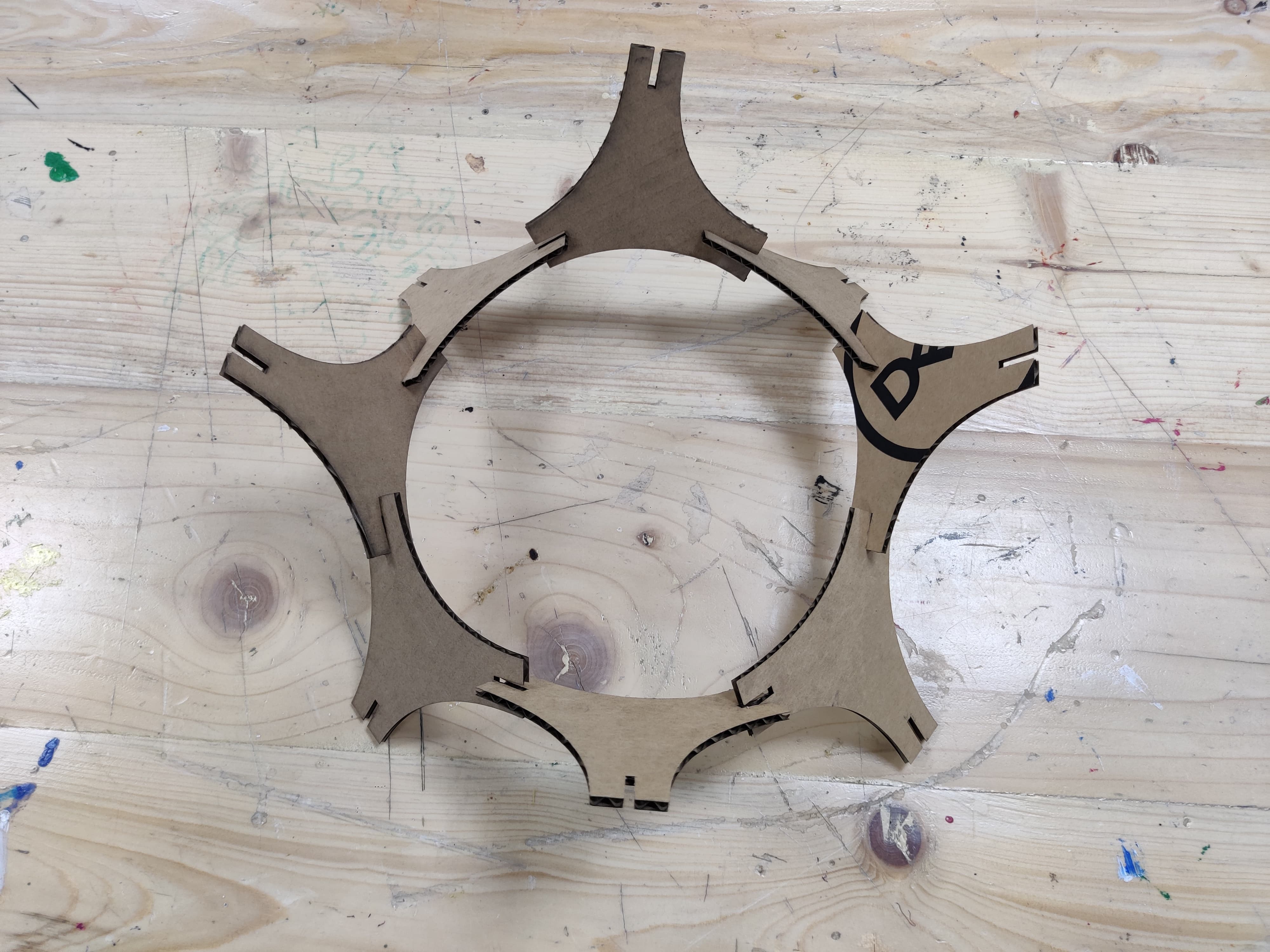
Step 5: The Final Design
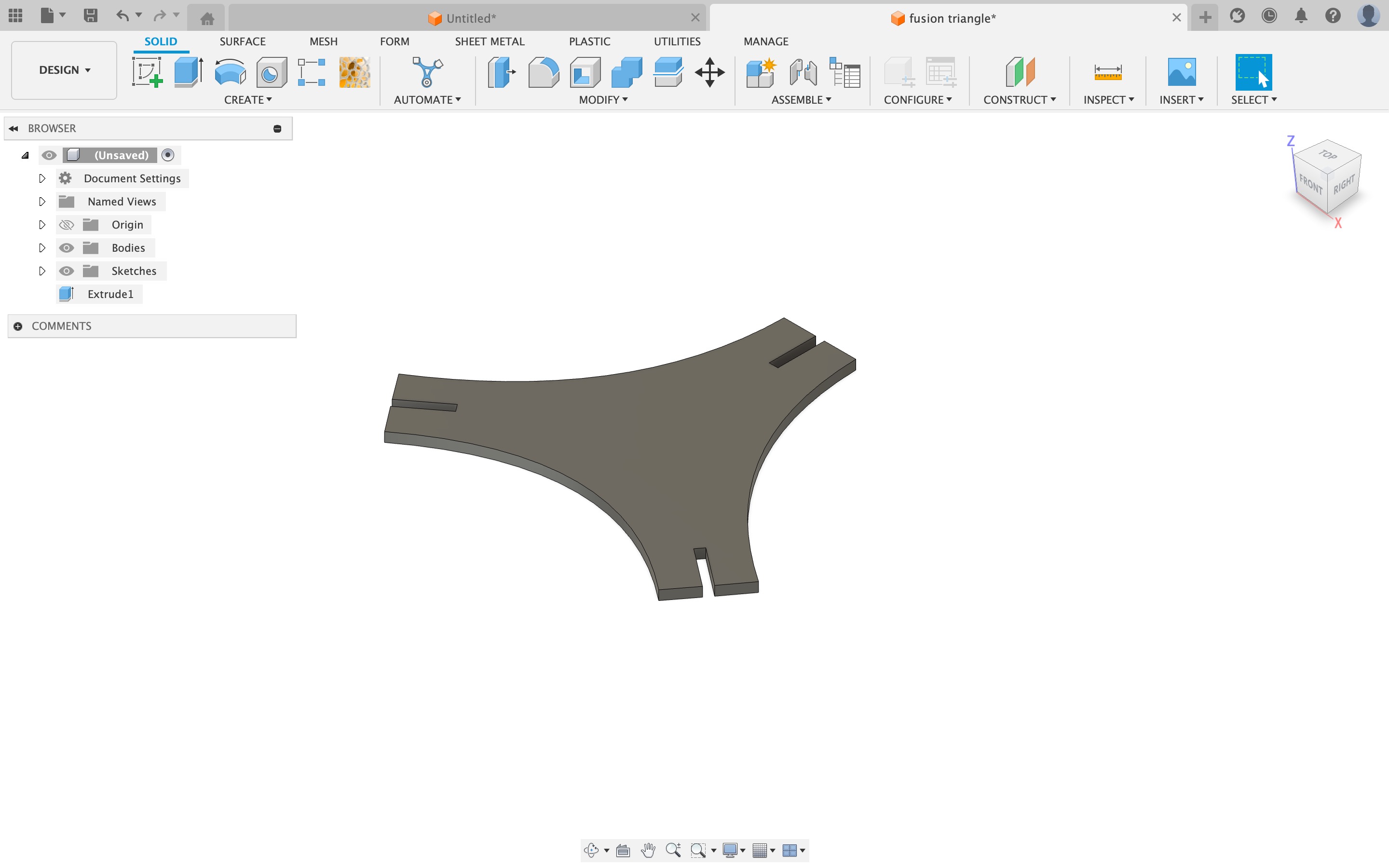
Step 6: Once design is made, export the file as DXF format.
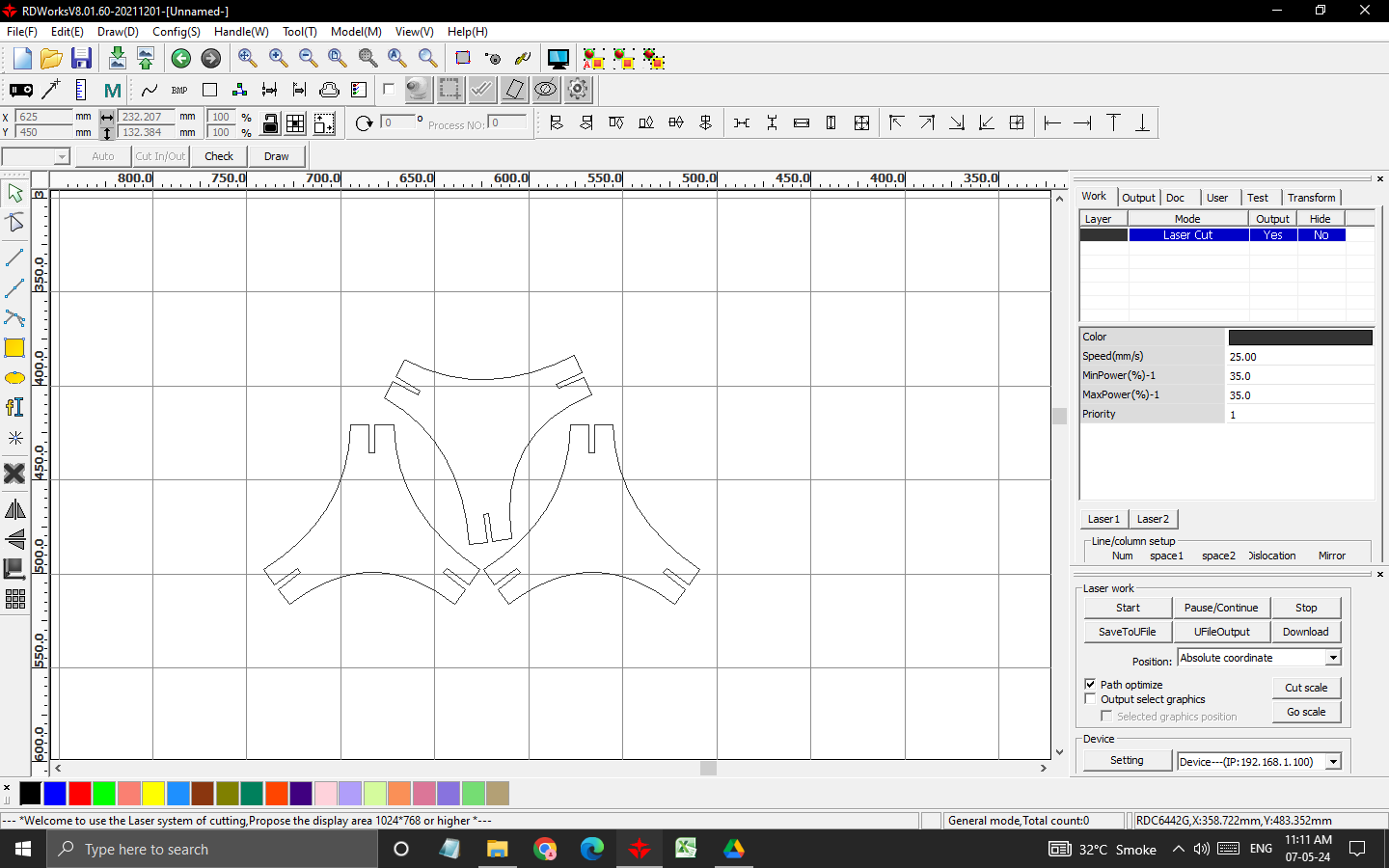
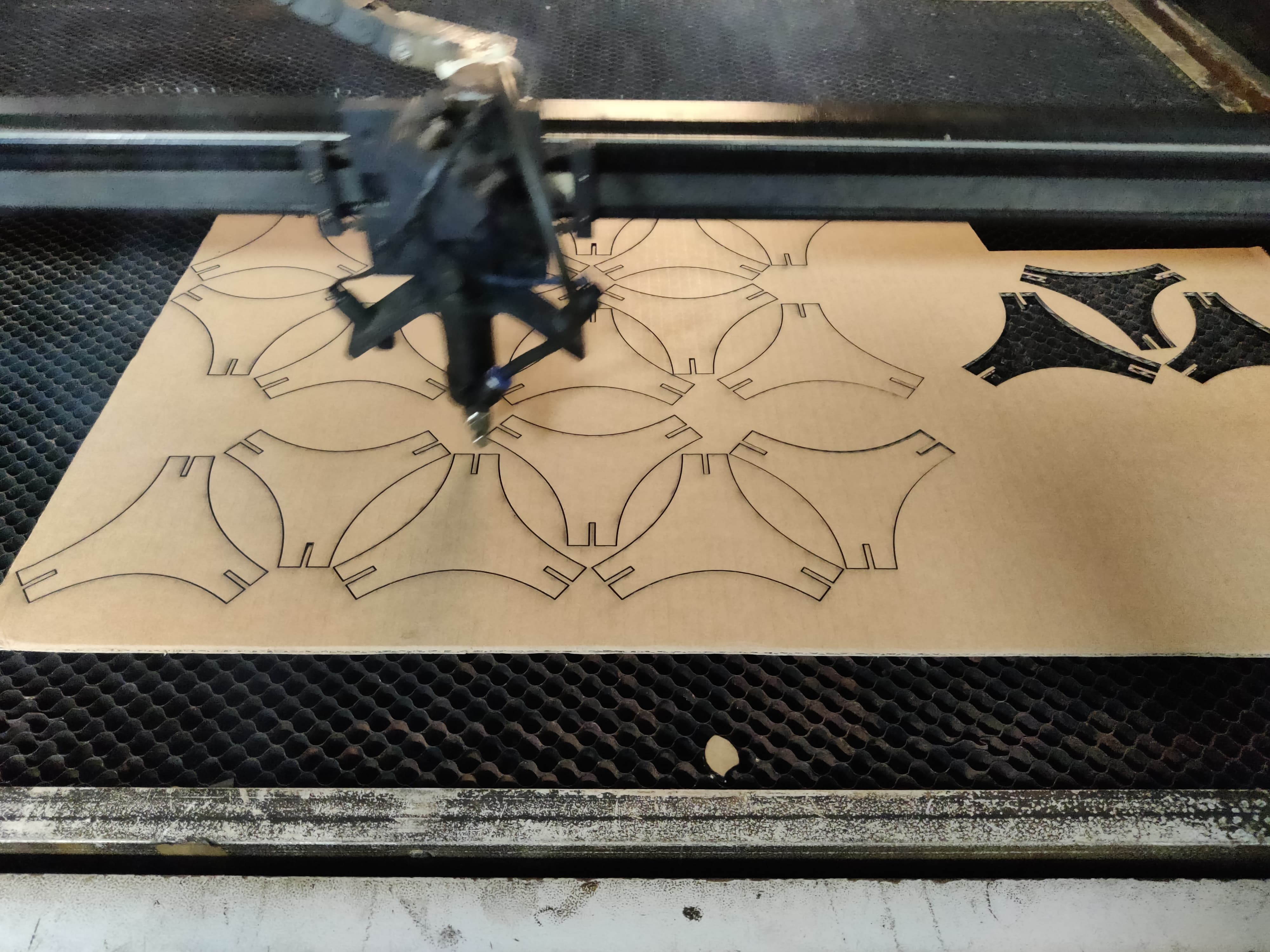
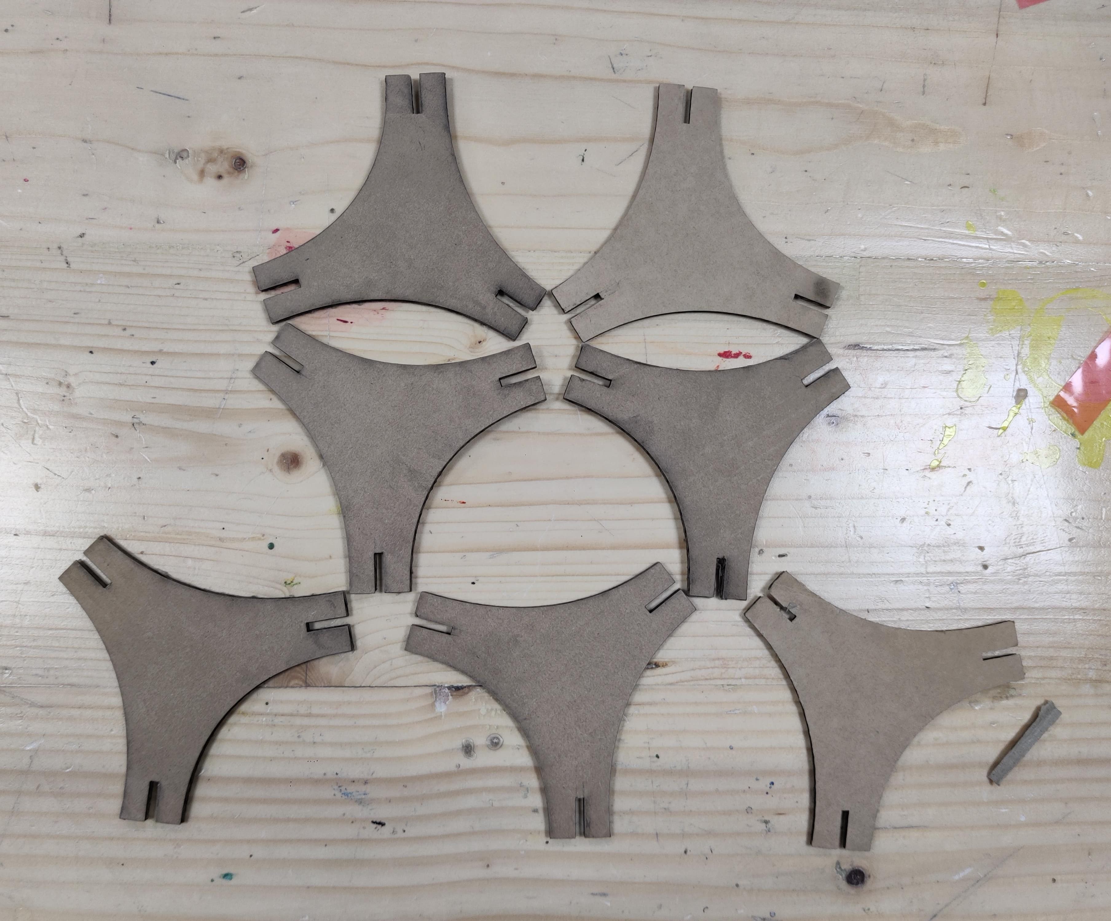
Cutting Process
All the steps of using laser cutting is same as mentioned above only the speed and power was different for this file.I started with cutting test pieces of this file. Speed and power I used was 25, 35, 35
Test cut fits well so I continued with other pieces.
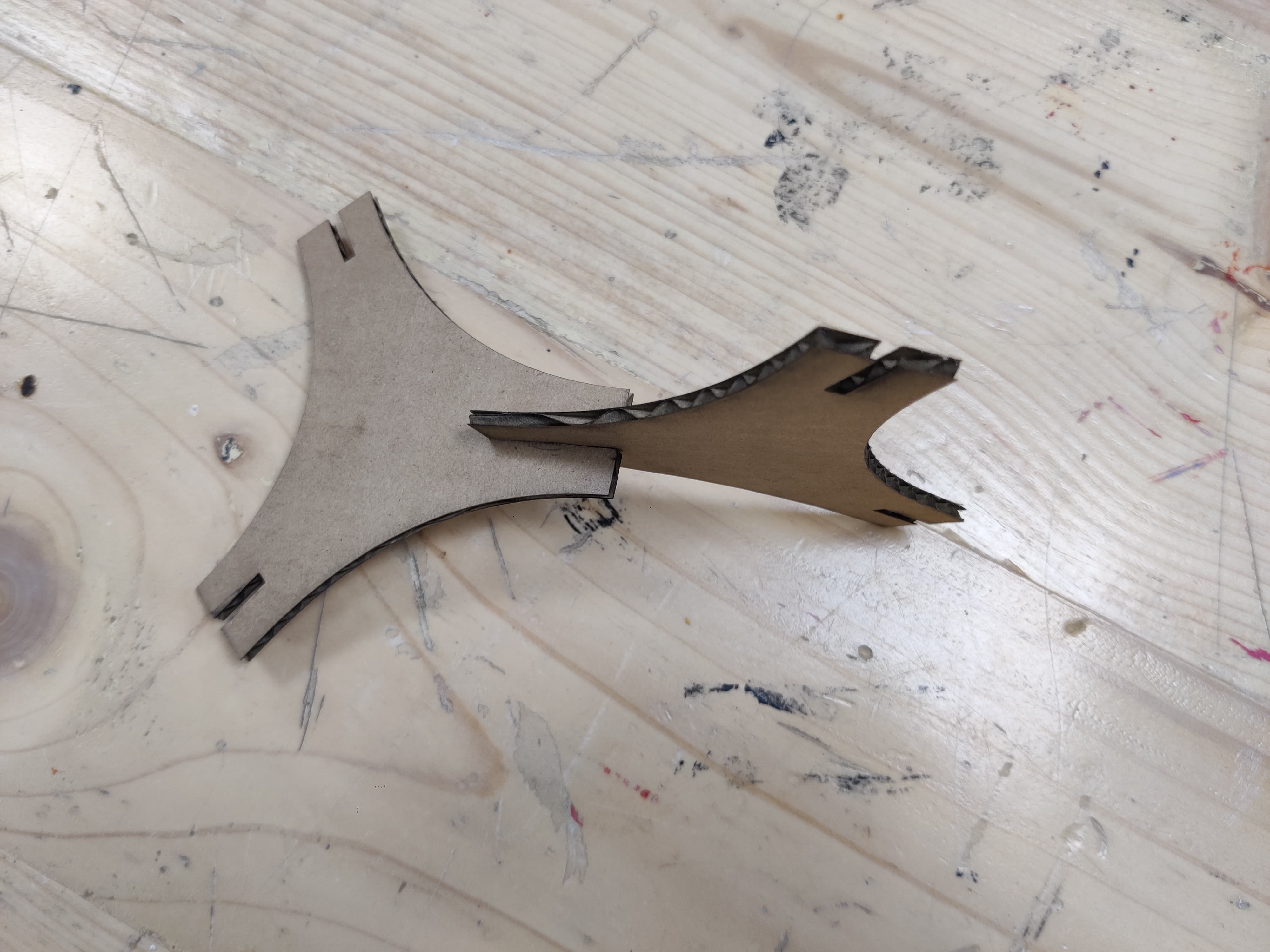
While cutting test cuts I realised I should increase the speed so this time while cutting the final model I changed the speed and put 30, 35,35
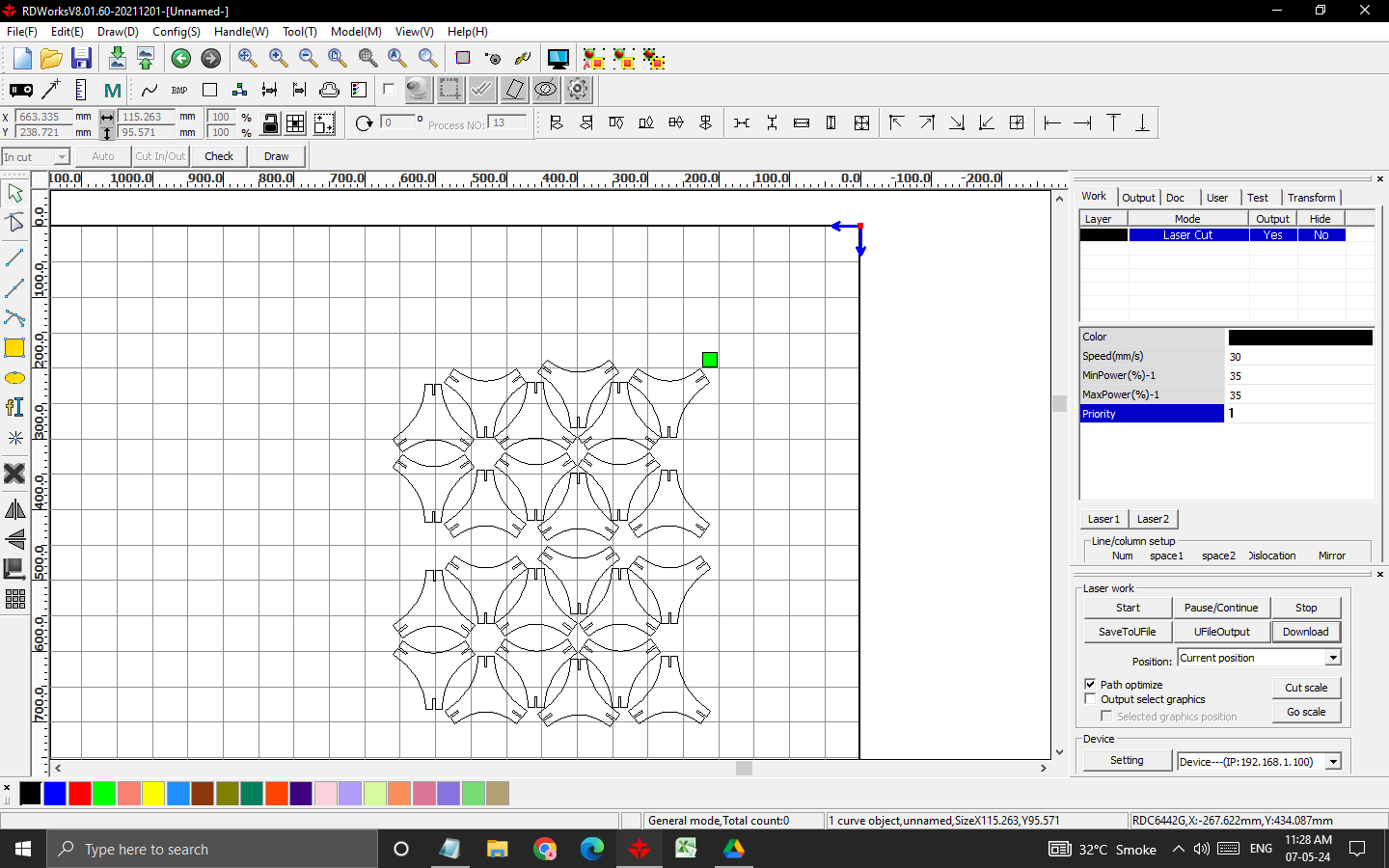
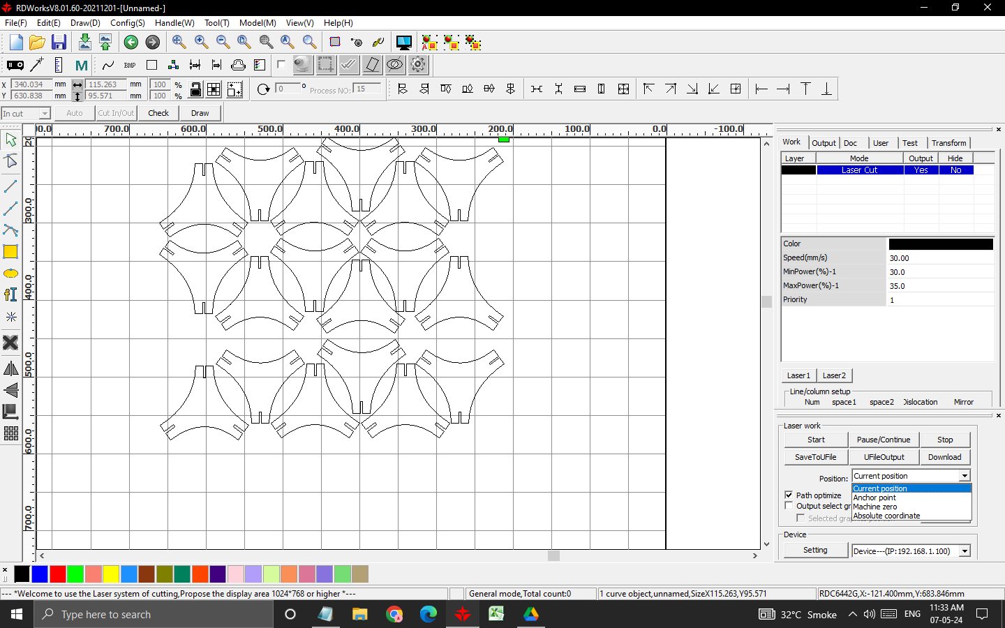
When I downloaded the file and when I was setting origin and doing frame it was not doing the frame where I have setted the origina nd then I debugged the error, the error was in the file itself, so you need to change the origin to current posistion which you can see at right bottom.
While cutting
Hero Shots
1st design
2nd design
3rd design
4th design
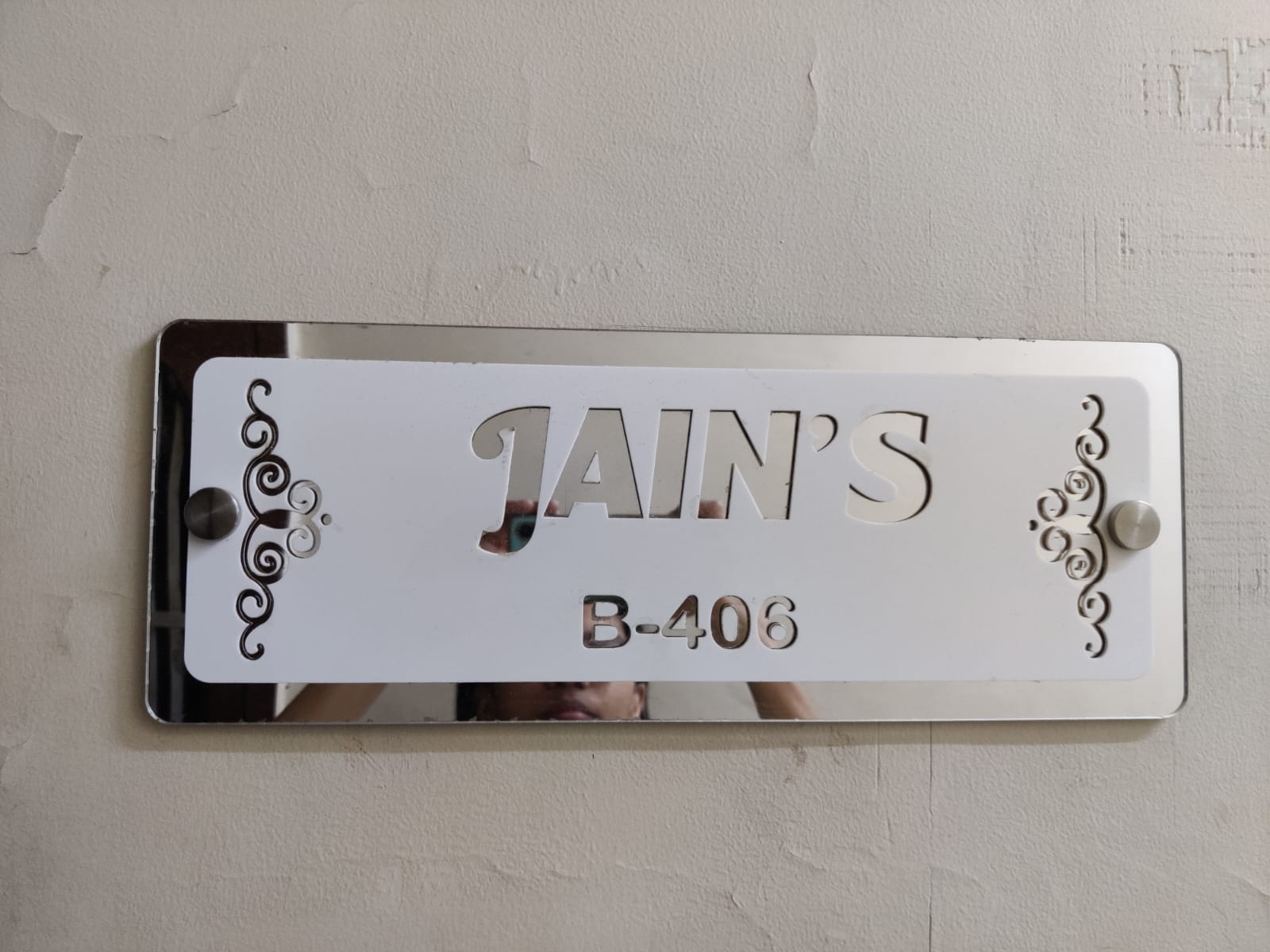
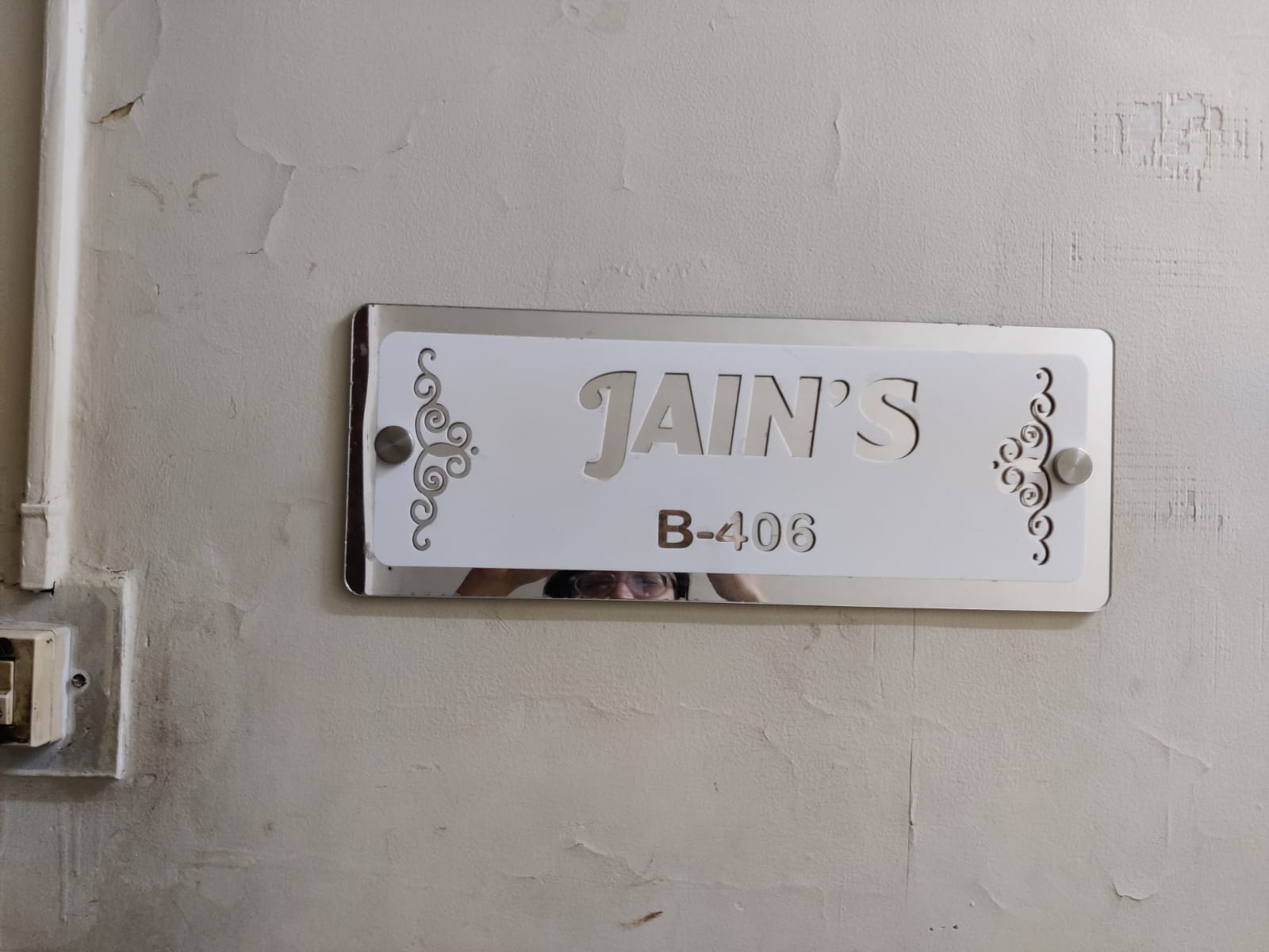
Nameplate
I made design of the nameplate for my home in week 2 on illustrator, to see the entire documentation Click heree.
To see the video of cutting the pieces, click below:
Hero Shots
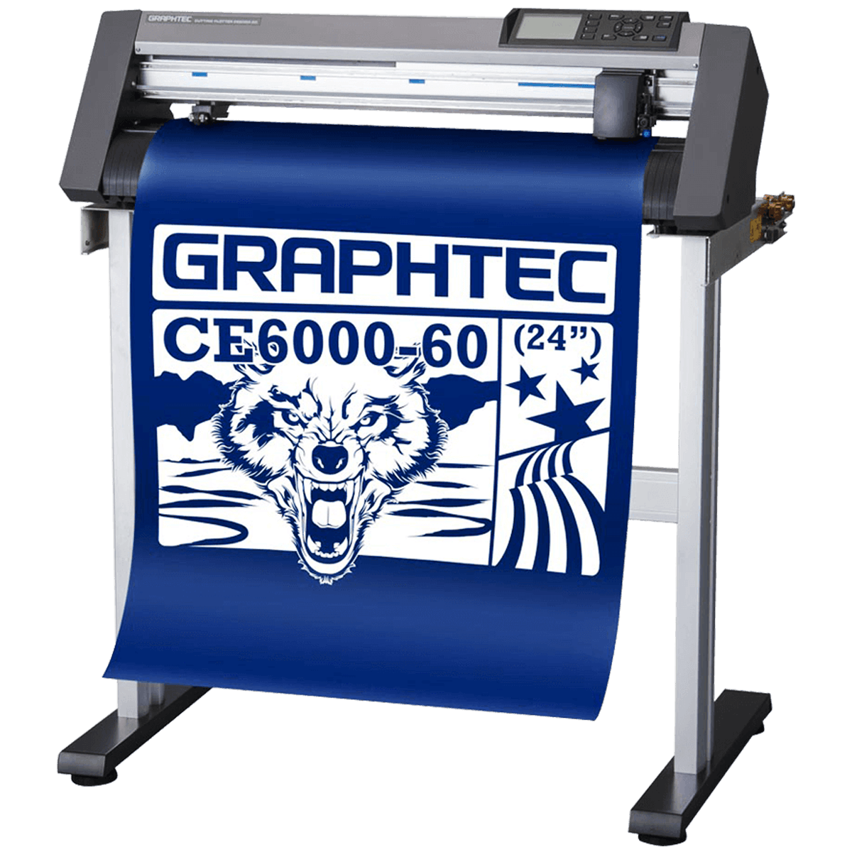
Exploring Vinyl Cutter at riidl
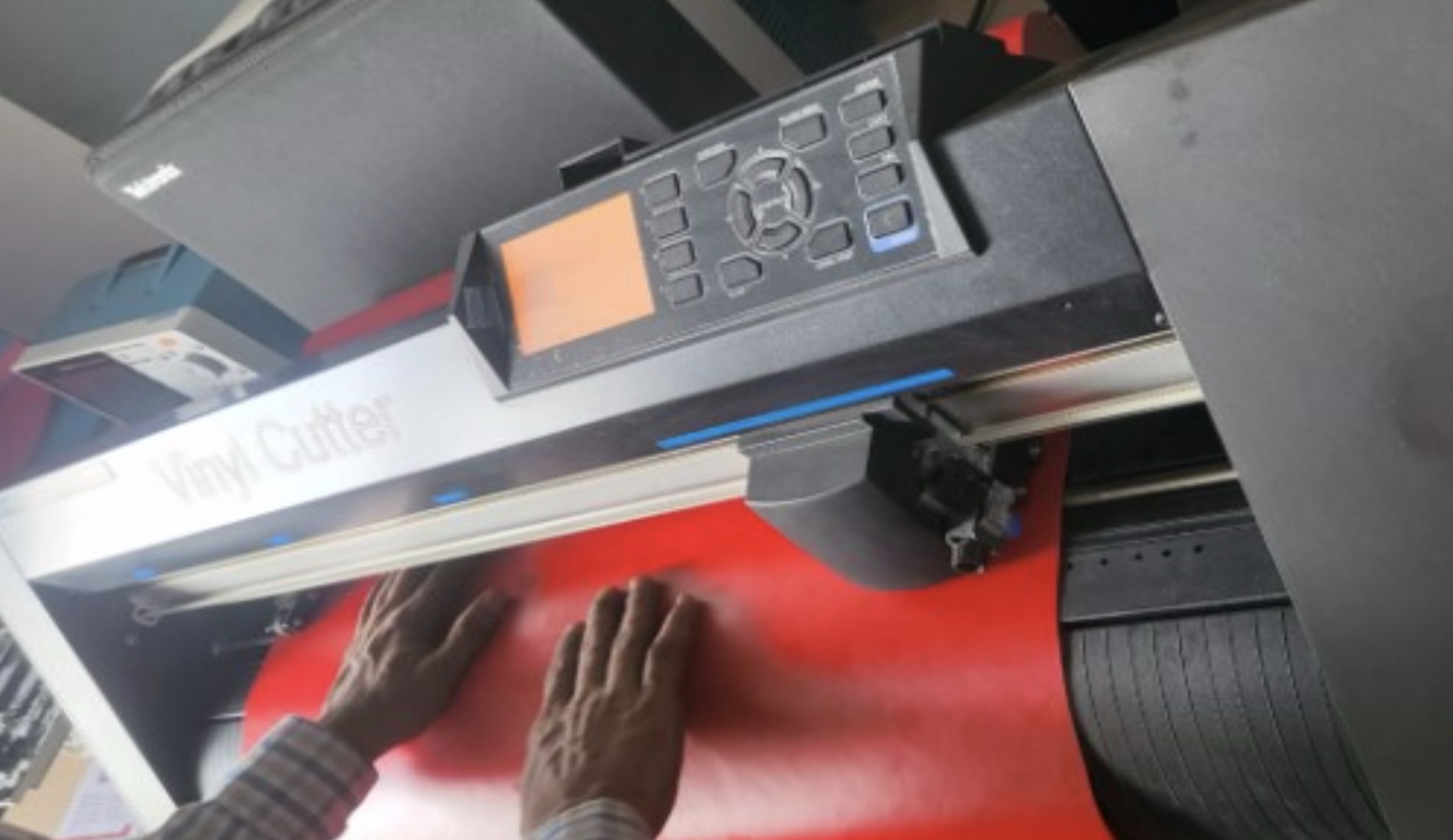
For this week's task, we're delving into the operation of a vinyl cutter. At riidl, we're equipped with a GRAPHTEC Cutting Plotter CE7000. As per Wikipedia, vinyl cutters like this one are capable of cutting computer-designed vector files containing patterns and letters directly onto rolls of vinyl. These rolls are then loaded into the cutter via USB or serial cable. Vinyl cutters are primarily utilized in the production of signs, banners, and advertisements. For our assignment, we attempted to produce a simple stickers to be used as a vinyl sticker for my book and tablet.
The Steps:
Step 01: Creating the Design
Certainly, the initial step involves designing the project. I utilized CorelDRAW software to craft a DXF file. Starting from scratch, I searched for an appealing image on Google. After selecting one, I pasted it into CorelDRAW and converted it into a vector format. Making some minor adjustments to the edges, I then exported the file in DXF format. (Further instructions on utilizing CorelDRAW or similar software are detailed on the Week 2 computer Aided Design

Step 02: Setting up the Software
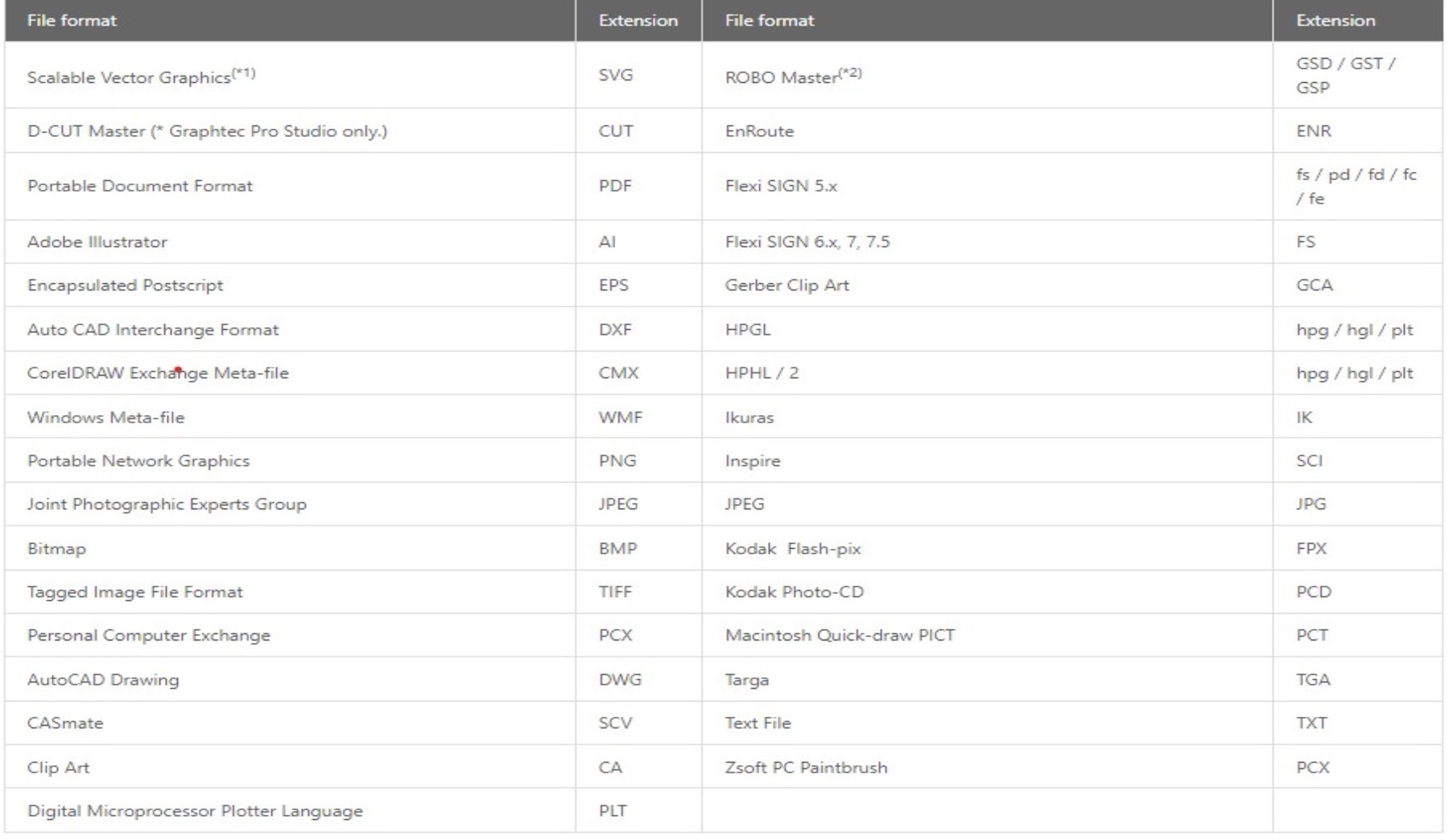
To access the Vinyl cutter software, Graphtec Pro Studio, you can download it from Here. The website also offers comprehensive explanations of all the software's capabilities and features in an intuitive manner. Additionally, the software supports various file formats, as listed below:
Step 03: Uploading the File
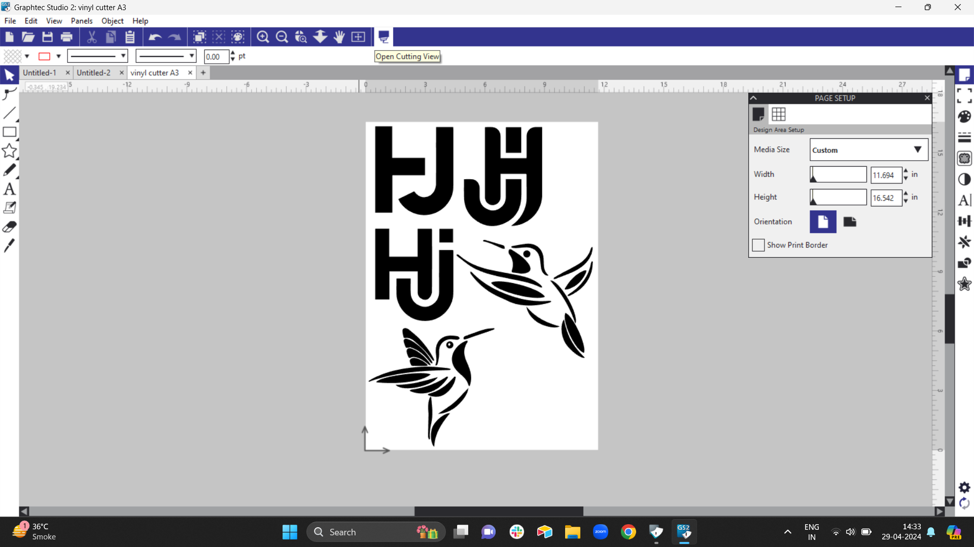
Navigate to "File" > "Open" and choose the desired file. Upon opening the file, verify its dimensions to ensure they are within the specified size. Additionally, you have the option to incorporate text or create simple drawings/figures directly within the software.
Step 04: Accessing the Cut/Plot Dialog Box
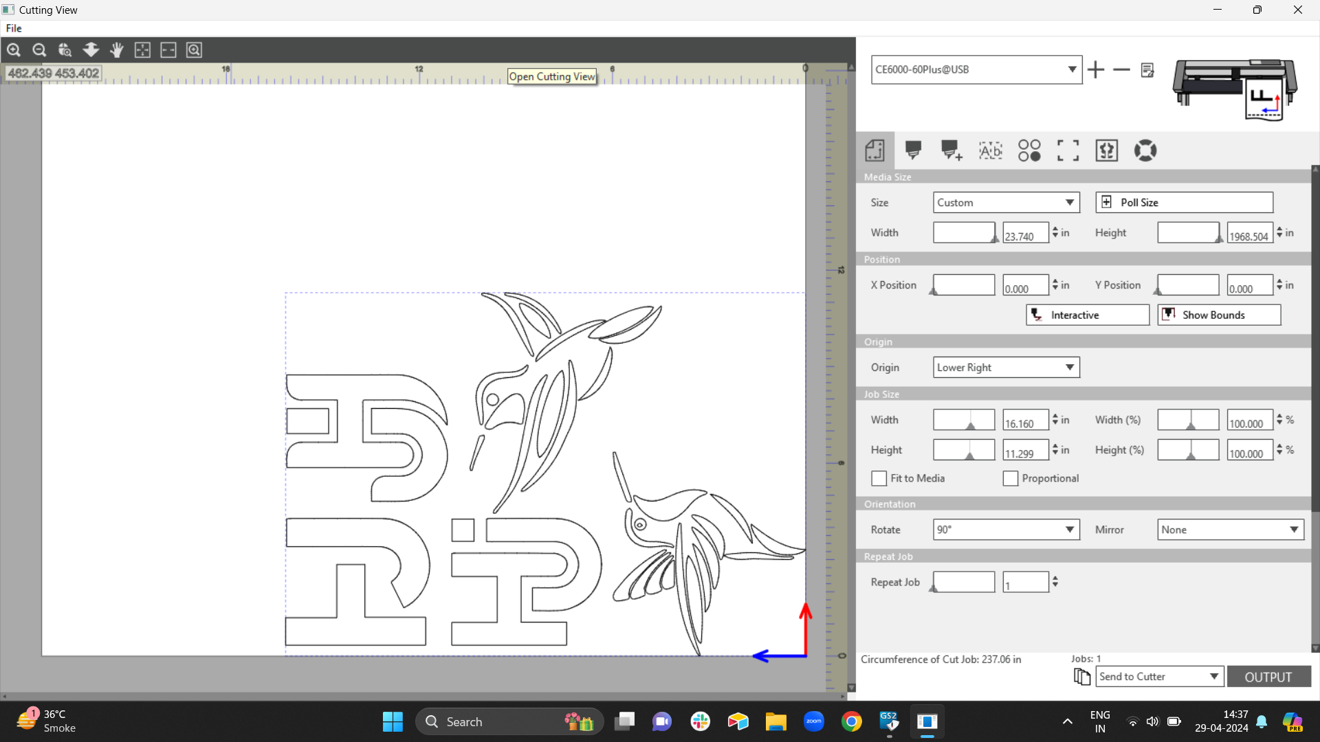
After preparing the cut file, select the "Cut/Plot" option. Ensure to configure and confirm fundamental specifications like the input material type (roll, in this instance), end-to-end dimensions, positioning, and the desired number of copies. Additionally, preview the design in the window on the right to gauge its size accurately.
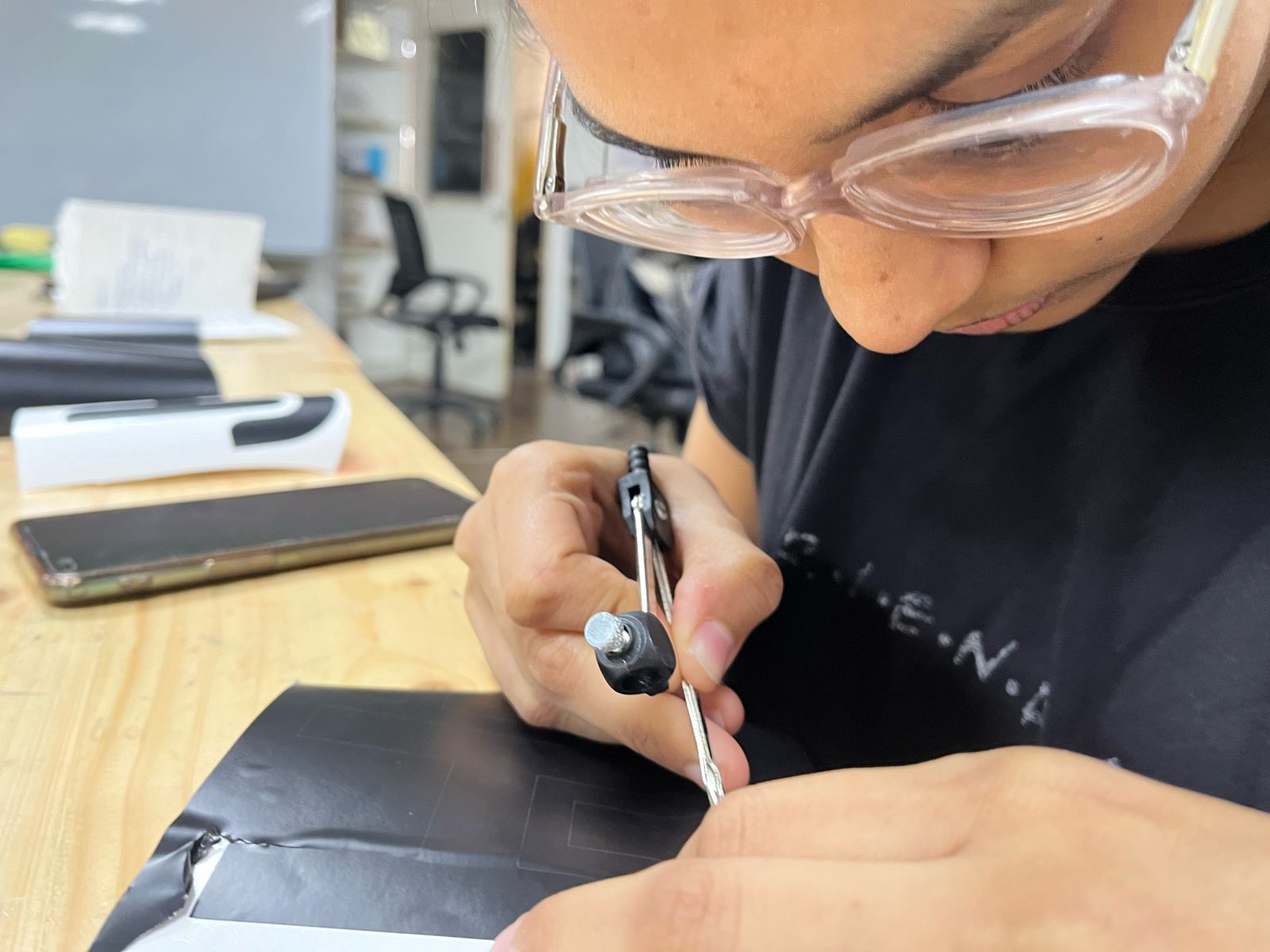
Step 05: Adjusting the Knife
Ensure the vinyl cutter knife is correctly positioned to achieve a clean cut through the top layer of the vinyl material. Adjusting the knife is a simple task, accomplished by tweaking the screw on the knife tool.
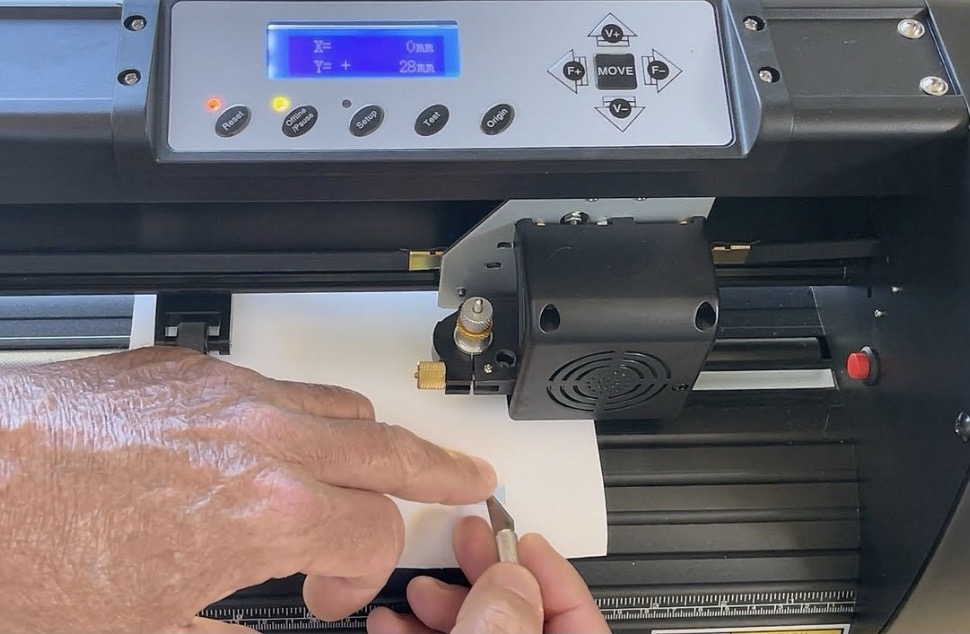
Step 06: Inserting the sheet
You must insert the vinyl sheet into the machine manually, as illustrated in the figure below:
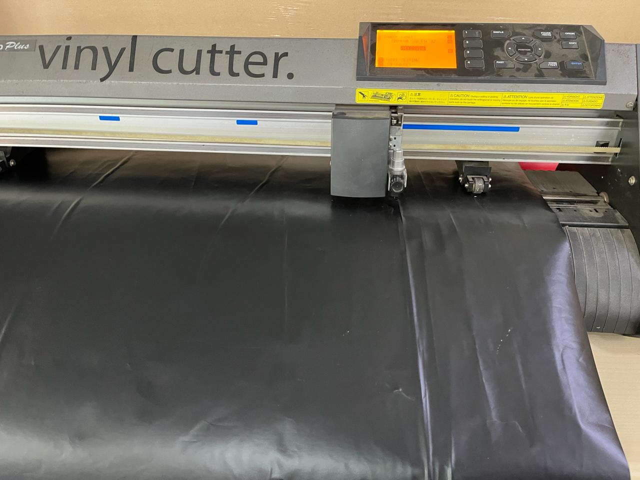
Step 07: Allign the stoppers
You need to flat the material put it in and allign the stoppers with the blue part above as shown in the image below
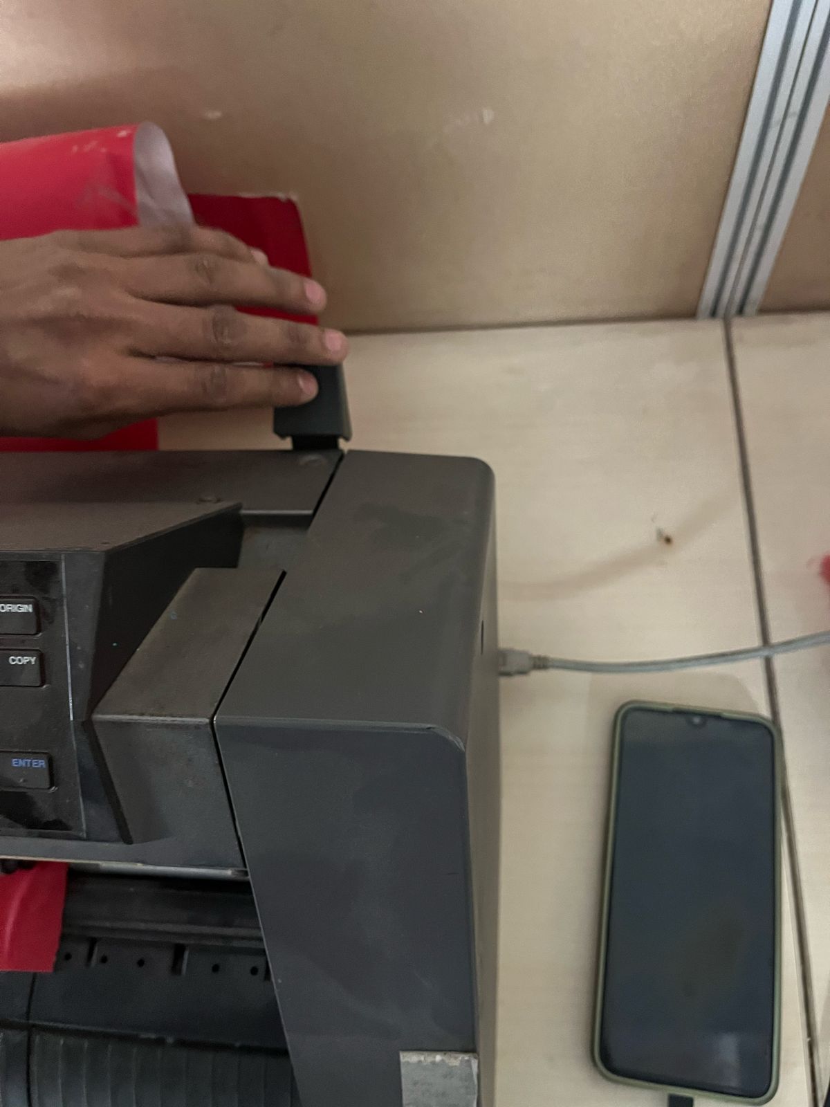
Step 08: Lock the handle
Lock the handle after alligning, if you do not lock it then when the cutting start the sheet will move.
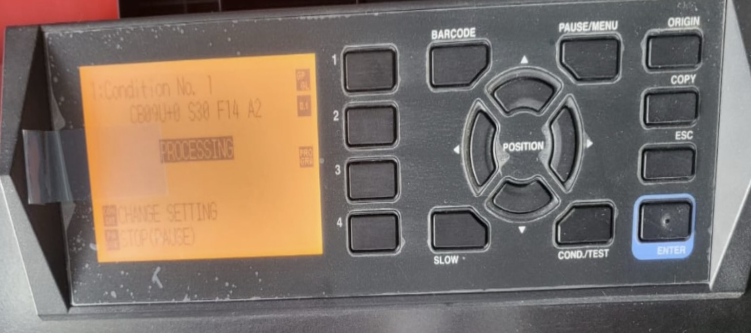
Step 09: Initiate the cutting process
When you commence cutting, the paper roll initially passes through without cutting to gauge the total size it will utilize. Subsequently, it retracts the paper before proceeding with the actual cutting process, as depicted in the figure below:
Step 08: Removing the sheet
Once the cutting is done push the handle down and remove your sheet, you will be able to see your design
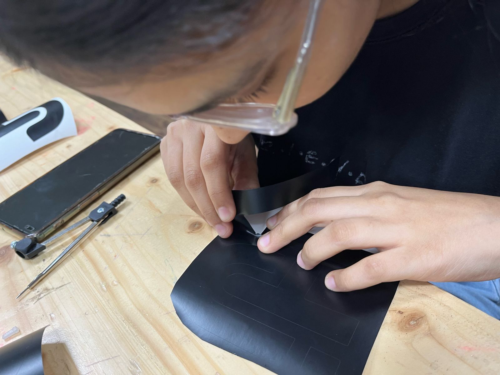
Step 10: Clearing the cut pieces.
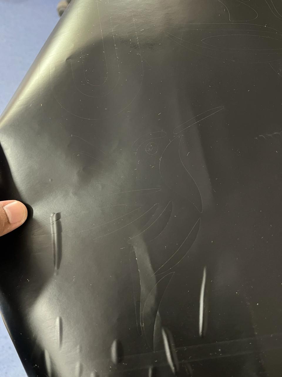
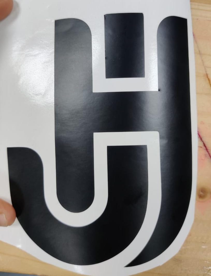
Remove the cut part cautiously, using tweezers if necessary. Rushing through this step can lead to errors, such as inadvertently tangling the tree branches, as depicted. However, the negative portion of the cut remained intact and can even be repurposed as a sticker.
I also learned a valuable lesson about the challenges of handling and adhering small vinyl cuts. For instance, when attempting to apply the "riidl" font next to the tree, I discovered that negative vinyl cutting is actually easier, especially when working with text.
Step 101: Mistake while removing
While removing the sticker I messed the first sticker as I pricked on a wrong path and it didn't turn good
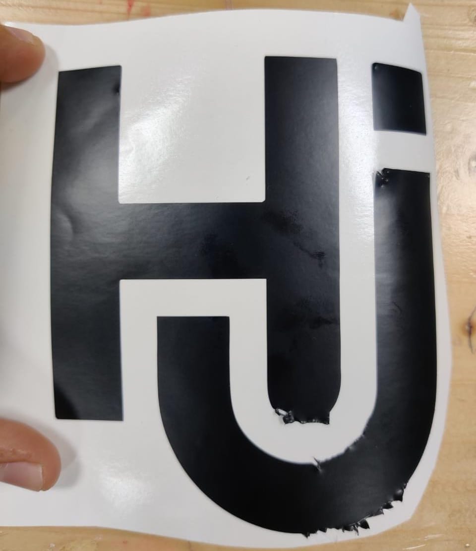
The next one I started removing more carefully and it turned out well.
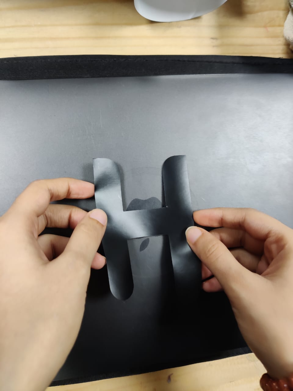
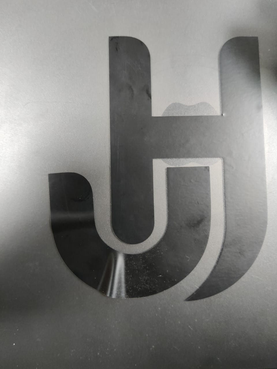
Step 11: Stick it on your object
If the design is complicated, after removing the negative part you need to use transparent vinyl sticker paper and put in on your positive vinyl sheet, Your main design will get transfer on that sticky sheet and put that sticky sheet on the object on which you want the sticker to be printed.
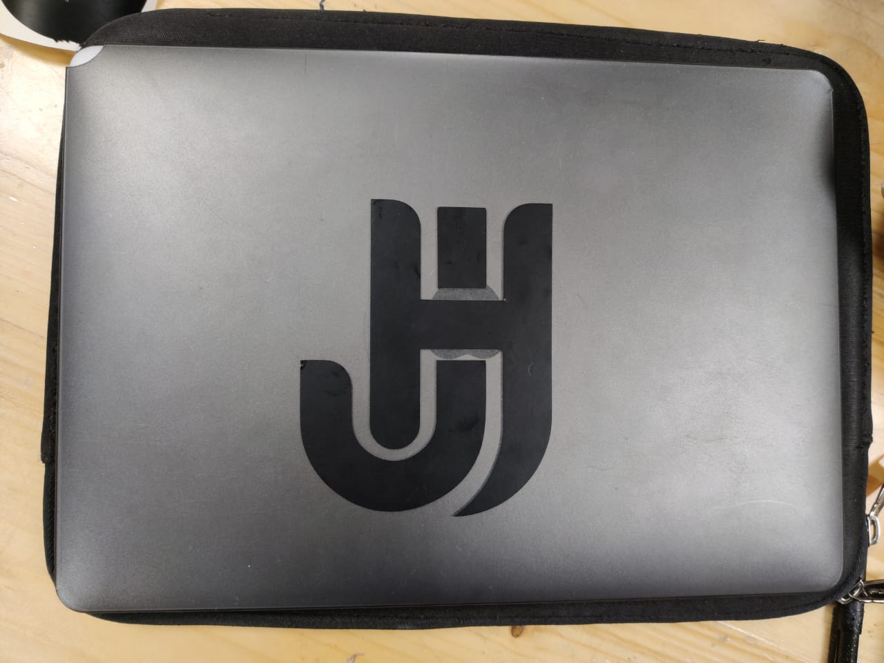
As my design was not complicated so I directly pasted it on my book and laptop.
Step 12: Mistake while sticking
Step 12: Hero shots
Group Work
Our group work is uploaded on siddhart agarwal's page. Link is Here Group work and the other half is done below.
Characterizing Laser Cutter's Focus, Power, Speed, Rate, Kerf, Joint Clearance, and Types
Focus
Proper focusing is essential for achieving precise cuts and engravings. Adjusting the focal point ensures the sharpest laser beam, which is crucial for clean and accurate operations. The laser focus must be adjusted to the correct height above the material's surface to optimize performance.
Power
Max Power:
The highest percentage of power the laser will produce during cutting or engraving. High power is generally used for cutting through thick materials.
Min Power:
The minimum percentage of power, particularly important for DSP devices. It is used during slow movements or sharp corners to ensure consistent performance.
Speed
The speed setting defines the feed rate of the laser when it is firing, typically measured in mm/sec or mm/min. The speed affects the quality of the cut or engraving:
High Speed:
Suitable for thin materials or marking.
Low Speed:
Better for thick or dense materials to ensure a thorough cut.
Rate
Rate refers to the frequency and number of passes the laser makes over the material:
Number of Passes:
The number of times the laser will trace the same path. Multiple passes at lower power can be used for intricate designs or thick materials.
Perforation Mode:
Allows cutting in a dotted line pattern without changing the design.
Kerf
Kerf is the width of the cut made by the laser, determined by the laser's beam diameter. It varies with material thickness and type:
Kerf Offset:
Adjustments made to compensate for the kerf, ensuring accurate dimensions and tight fits. For example, if making inlays or joints, accounting for kerf ensures pieces fit together correctly.
Joint Clearance
Joint clearance is adjusted to ensure that parts fit together correctly. This involves accounting for the kerf and possibly offsetting the cut:
Clearance Adjustment:
By adjusting the cut inward or outward, the laser cutter can ensure tight or loose fits depending on the requirements.
Types of Laser Operations
Cut:
Tracing the laser along the vector path with high power to cut through the material. Single or multiple passes can be used based on material thickness.
Scan (Fill):
Engraving by filling the interior of a vector shape. The laser moves back and forth, filling the shape with lines spaced at a set interval.
Fill+Line:
Combines filling and cutting. The interior of the shape is filled first, followed by a cut along the outline.
Conclusion
Laser cutting and engraving involve precise control over focus, power, speed, rate, kerf, and joint clearance. Proper focusing ensures a sharp laser beam, while power settings adjust the intensity for cutting or engraving. Speed and rate affect the quality and depth of cuts. Kerf must be accounted for to ensure accurate fits, and joint clearance adjustments are necessary for assembly. Understanding these parameters allows for precise and effective use of laser cutters in various applications.
To know more about the machine settings visit this link:
Learnings
Throughout the computer-controlled cutting week, I focused into understanding the intricacies of laser cutting machines. In our group task, we focused on characterizing various aspects of our laser cutter, such as focus, power, speed, rate, kerf, and joint clearance. One significant learning came from our joint test, where we realized the importance of accounting for kerf to ensure proper fittings. Additionally, our modified comb test for kerf shed light on the complexities of measuring and understanding kerf, highlighting the need to consider material, thickness, and fitting factors. Under the guidance of our mentors, I gained insights into the nuances of laser cutting and the importance of thorough experimentation in understanding machine behavior and optimizing designs.
Conclusion From this Week
I knew laser cutting already but we never learned about focal length, kerf, parametric kit so this was a new thing which I learned, at the start I made mistakes while exploring finger joints then I realised the mistake, so it was a good detailed learning of things which you already know. Vinyl cutting was an entirely new machine which I learned, I think the entire process is time consuming if you have intricate design but the outcome is amazing
Download Design files
Illustrator ai file of 7mm to 6.7 mmIllustrator ai file of 7mm to 7.8 mm
Lampshade
Parametric design kit
Vinyl cutting
New Parametric design files
Image Credits
All images of cover page are credited below:
https://images.app.goo.gl/BvNgZHPzzHPgrG7s7.
https://images.app.goo.gl/HX6KBB3aPXHTsBLi6
https://images.app.goo.gl/kcSr47HRd6FjN1WQ8
https://images.app.goo.gl/gYHC4JzCSjGewTw47.
https://images.app.goo.gl/zASdyrNNDzUkGtzm7
https://images.app.goo.gl/C9LM7ok4zmBYCuEr7