Add an output device to a microcontroller board we’ve designed and program it to do something.
For this week, I decided to use the board I designed for week 10, which is a board for an Xiao RP2040.
For my final project, I need to control the speed of a DC motor, so that is what I will do this week.
In addition to the board with the microcontroller, I need other materials such as a 10k potentiometer, a
TIP122 transistor, a 1k resistor, a 1N4007 diode, and the motor.
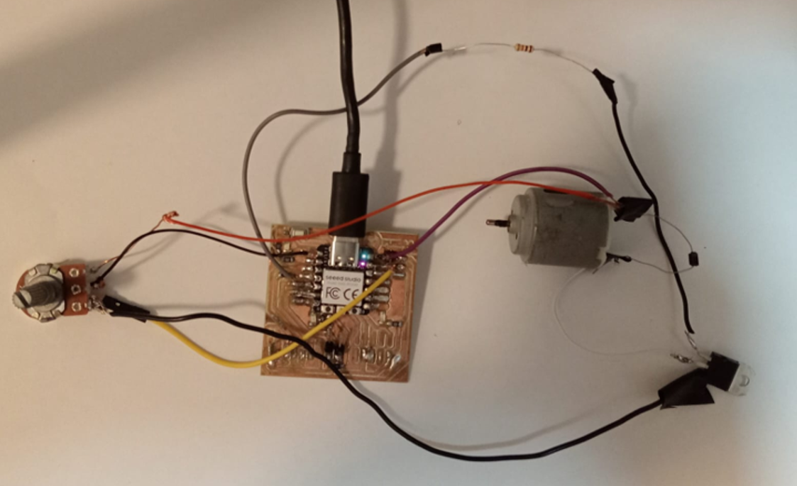
Connections
I connect the collector of the TIP122 to one of the motor terminals, the other motor terminal
to the positive power supply (Vcc) and the emitter of the TIP122 to ground (GND).
For the diode I connect the cathode of the diode (the side with the band) to the positive terminal of the motor
and connect the anode of the diode to the motor terminal that is connected to the collector of the TIP122.
This is to protect against reverse voltages
generated by the motor.
Then I connect a 1kΩ resistor between the GPIO pin of the XIAO RP2040 (for example, GPIO 2) and
the base of the TIP122. I connect one end of the potentiometer to Vcc. I connect the other end of the potentiometer
to GND. I connect the wiper pin of the potentiometer to an ADC pin of the XIAO RP2040 (for example, GPIO 26/A0).
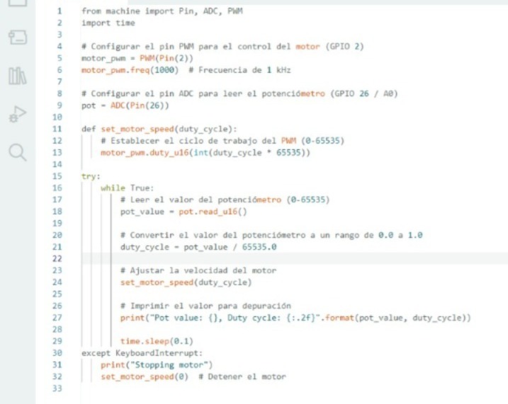
Code
This code reads the value of the potentiometer and adjusts the duty cycle of the PWM to control the speed of the motor (you can find this code in the 'Files' section below.).
Testing
Before soldering everything, I decided to do a test on a breadboard.
It work!!!
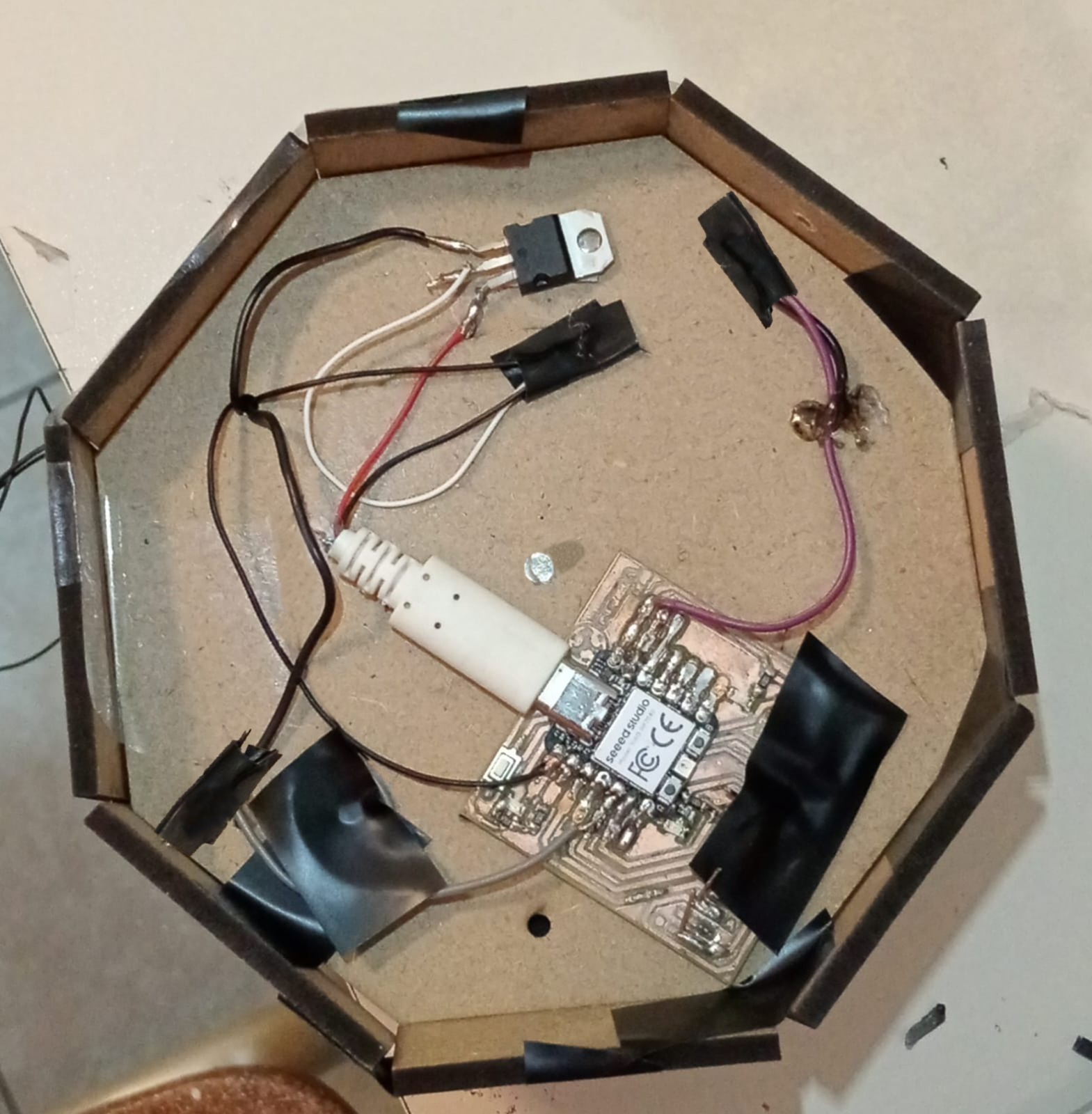
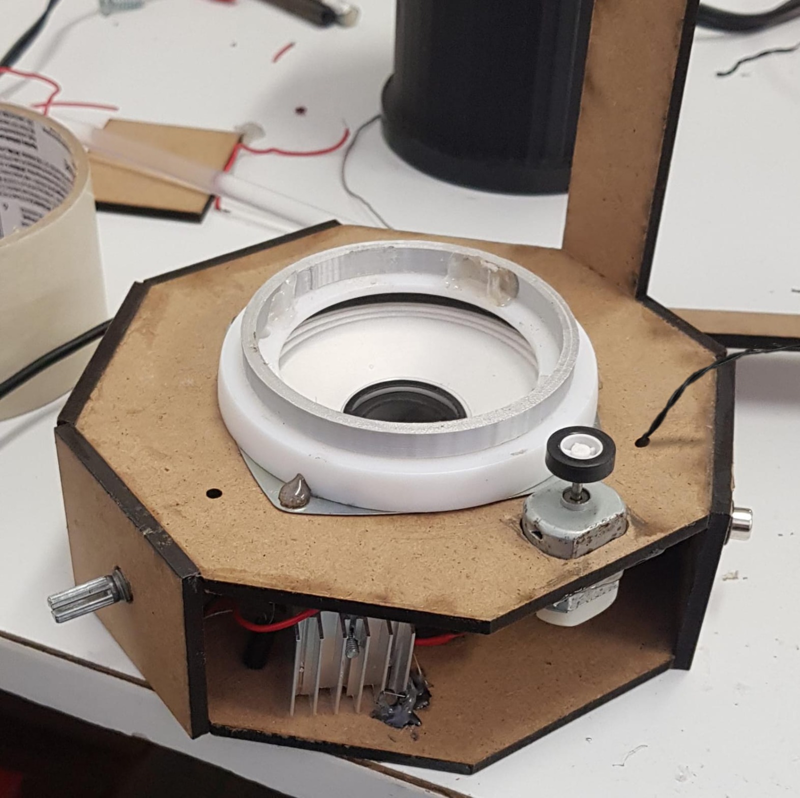
Now I just have to solder everything and put it all in place. By the way,
I also added a heatsink to the transistor when assembling everything. In the speaker, the motor with the potentiometer
are at the bottom, and the board is at the top. I also added a 7805 regulator at the top because the power
source for my speaker is 6V, and the board has a maximum input of 5V