Output devices
Unfortunately, for this week, I couldn't use my Week 8 board because it was missing pins. So, I decided to create a new board to try this week.
Team Practice
Here its the link of our team practice.
COMPONENTS LIST
| Material | |
|---|---|
| Microcontroller | Attiny 44 |
| Led | red color | Resistor | 1k - 2 pieces | Button | 1 piece |
This ones and a Arduino 1 are the components that I used thius week for my output device
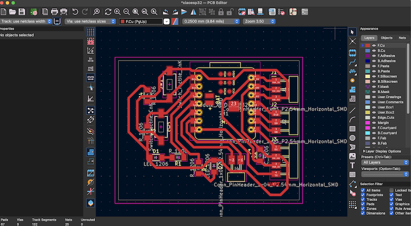
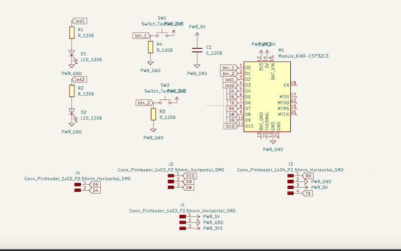
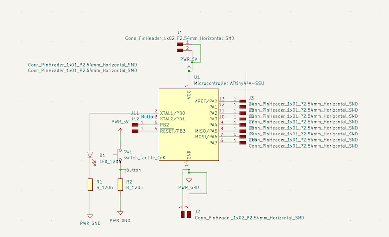
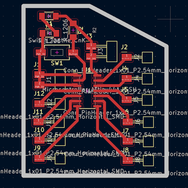
KiCad PCB desing
Just like in Week 8, I used KiCad to design my schematic and PCB. I basically used the same components, but with the Attiny 44 microcontroller to learn with a different one.
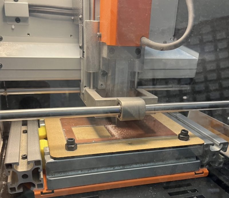
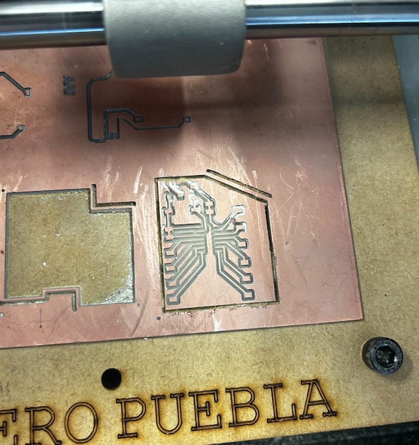
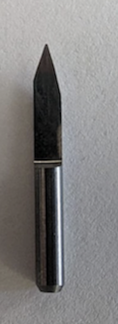
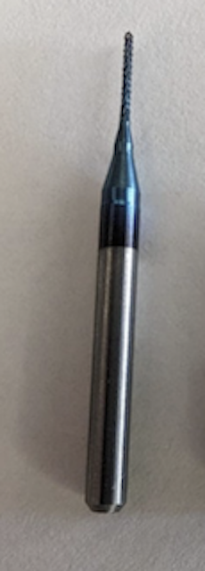
PCB CUTTING
For etching and cutting my board, I used Rolan PCB as in previous times, along with the mods program to generate the RML format.
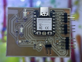
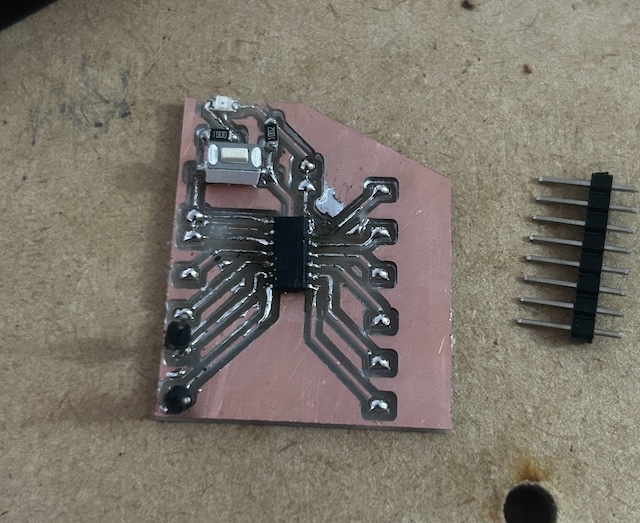
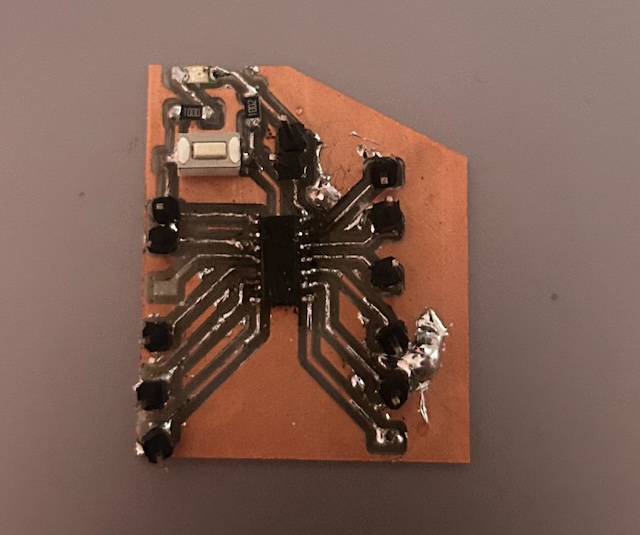
BOARD SOLDERING
For soldering, I follow my design and place the majority of my pins on ground, 5V voltage, and the remaining pins of my Attiny44.
PROGRAMMING
Programming was different from previous times because this time I used the Arduino UNO. I took into account the use of the Attiny 44 to understand everything about the outputs, as I used an OLED screen for my output.
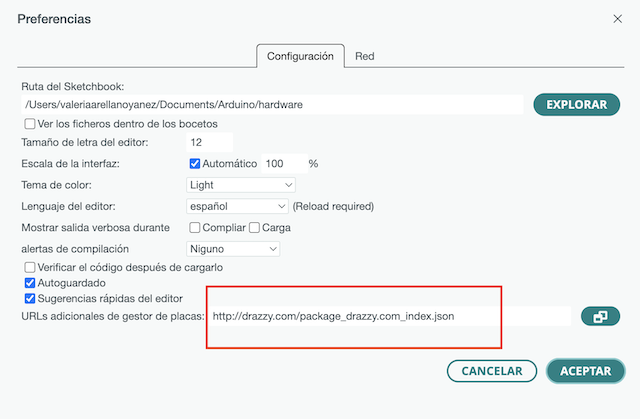
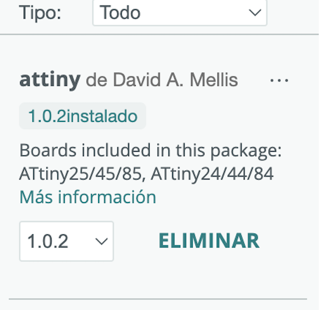
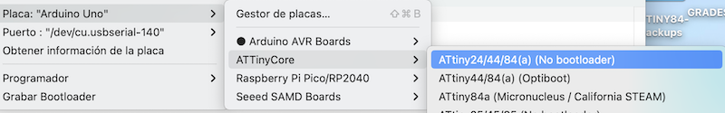
STEP 1
Install the Attiny 44 library in my Arduino IDE.
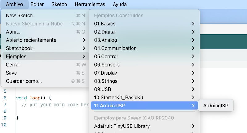
STEP 2
Then program the Arduino as an ISP, where an Arduino ISP example is loaded and connected to the computer to load it.
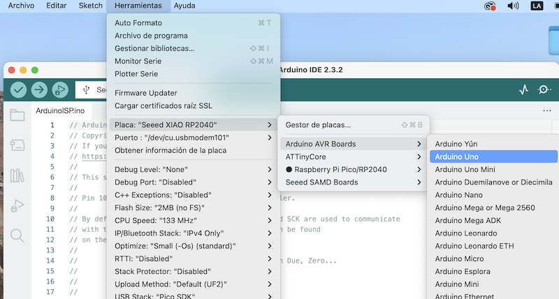
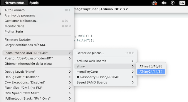
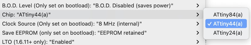
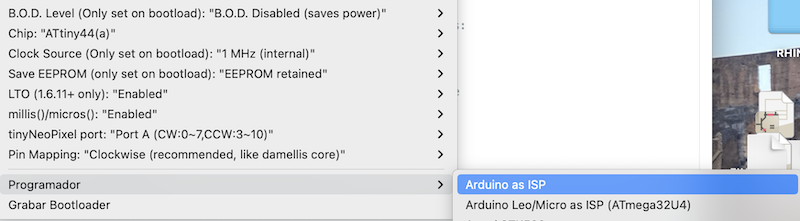
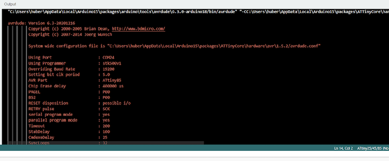
STEP 3
Then configure the Attiny board, clock, and programmer to be used.
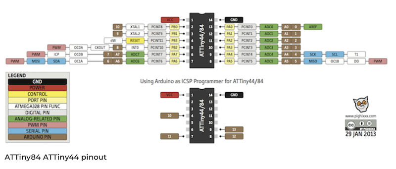
STEP 4
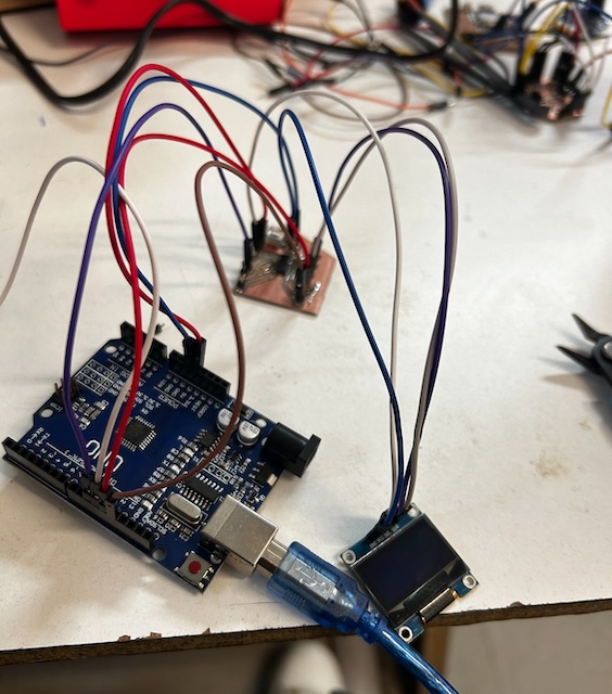
At this point, I connect the pins of my new board to the Arduino using jumpers.
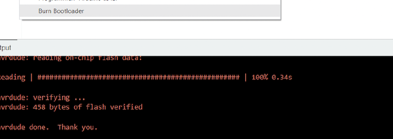
STEP 5
Once everything is selected, I select the option to burn the bootloader to be able to use the Arduino as a programmer for the Attiny 44.

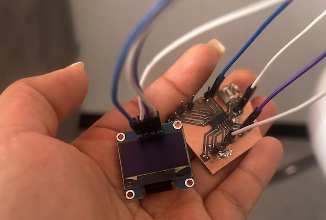
STEP 6
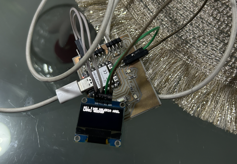
Once this is ready, I connect my OLED screen to the 5V, GROUND, SDA, SCL inputs to the corresponding pins.
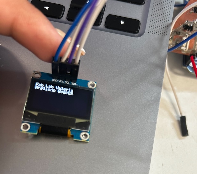
STEP 7
I design my code to display text on my OLED, in this case, it was my name and the week of work.
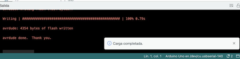
STEP 8
I upload my design to Arduino, and it works.
FINAL RESULT with another PCB
Similarly, create a new board following the same process as the previous ones, and connect the OLED to this board using the same previous process.