Computer controlled machining
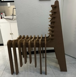
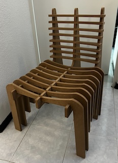
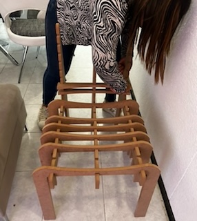
For the design process of creating and using a CNC router, I decided to create a reclining chair that is divided into layers.
Team Practice
Here its the link of our team practice.
COMPONENTS LIST
| Material | |
|---|---|
| MDF | Size 1200 x 2400 mm and 15mm thickness |
| END MILL | 6.35 mm diameter or 1/4 |
Use this 6.35 mm END MILL because it allowed for a clean cut due to the thickness of the material.
MACHINE PROPERTIES
| PROPERTIES | Description | Supplier | Result |
|---|---|---|---|
| Machine | CNC | ASIA ROBOTICA | max 24000 RPM |
| Material | MDF | - | 15mm |
| Diameter | Tool diameter | End mill 1/4" max RPM 28000, 2 flutes | D=0.25 inch |
| Deep of the pass | How much does the tool cut per passs? | It is specified by the tool supplier, or 50% of the diameter of the tool. | 0.125 inch |
| Stepover | Distance that the tool has between each pass. | Depends on the application | 40% in bas reliefs |
| Spindle speed | How fast is the spindle going to turn? | As per the reccomendation table, in this case our machine works better with this rpm | 16000 rpm |
| Feed rate | Feed per tooth or Chip Load | As per the reccomendation Amana tools/ or Chip load x rpm x # flute | 200 ipm = 5075.98 mm/min |
| Plunge Rate | Forward speed | Depends on your process and material | To start I use 800 mm/min. |
Piece creation and disassembly of my object (AUTOCAD):
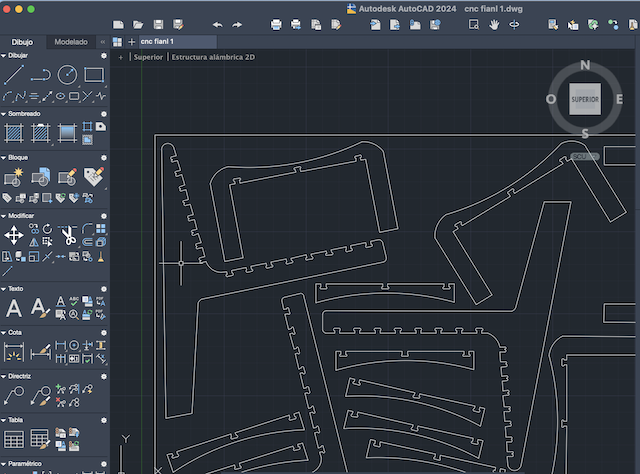
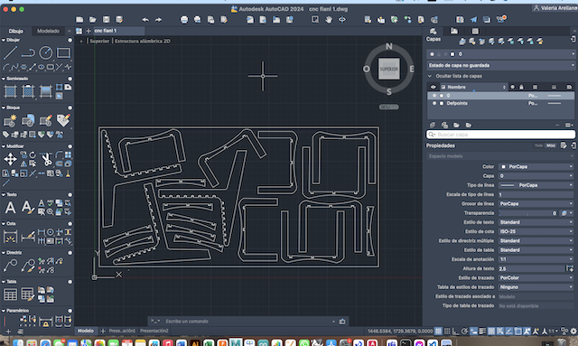
For the creation of my pieces, I chose to work in the AutoCAD interface to ensure the symmetry and accuracy of my measurements and design.
Step 1
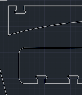
I opened a new sketch in AutoCAD, using various tools such as line, dimension, trim, tangent, and others to generate the disassembly of the chair into parts.

Step 2
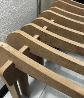
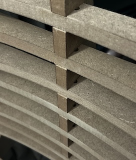
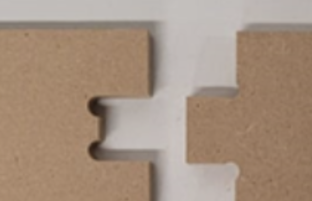
It's worth noting that the assembly measurements correspond to the thickness of my material, in this case, a 15mm MDF.
Step 3
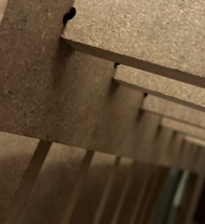
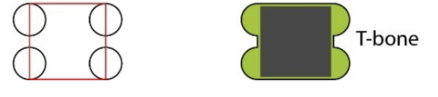
I also considered adding a T-BONE to each part of the assembly, with a thickness equal to the diameter of the router bit to be used for cutting, which in this case was 6.35mm.
Step 4
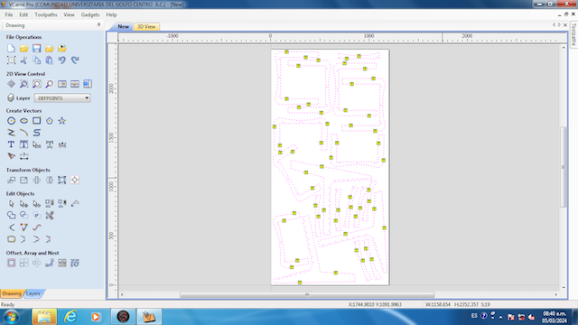
Once the disassembly was ready, I arranged everything to fit on a 2.40 x 1.20 meter MDF board.
Step 5
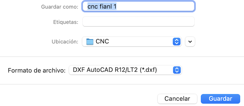
I exported the document in .dxf format.
Design validation in Vcarve:
The Vcarve program helped me simulate the router cutting process before sending it for actual cutting, allowing me to identify any potential errors or issues.
Step 1
I opened the Vcarve program.
Step 2
I opened the previously saved .dxf file.
Step 3
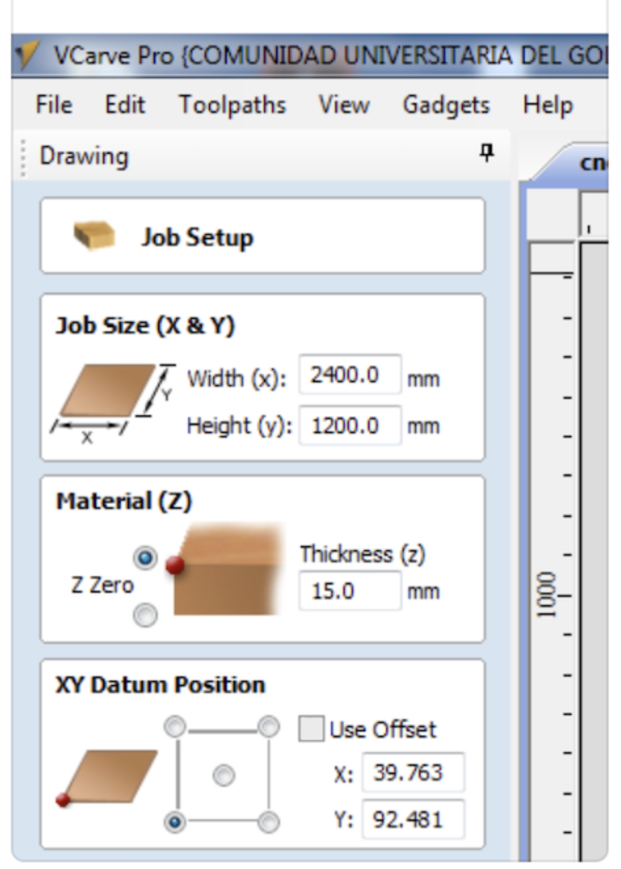
I adjusted the table dimensions (1200 x 2400 mm), specified the material thickness (15mm), and marked the origin in the bottom-right corner.
Step 4
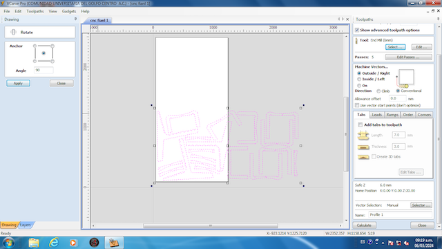
I rotated the pieces to fit the workspace at 90 degrees.
Step 5
Once ready, I went to the tools on the right and selected "Toolpath Profile," entering the following parameters:
| Parameters: | |
|---|---|
| Tool | End Mill 6.35 mm |
| Passes | 5 |
| Machine vectors | Outside |
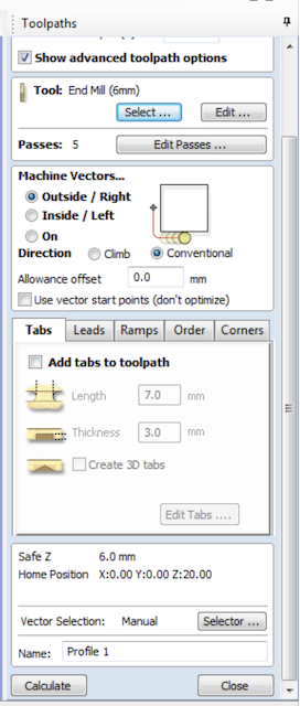
Step 6
I also added tabs to hold the pieces during cutting, placing them in various locations.
Step 7
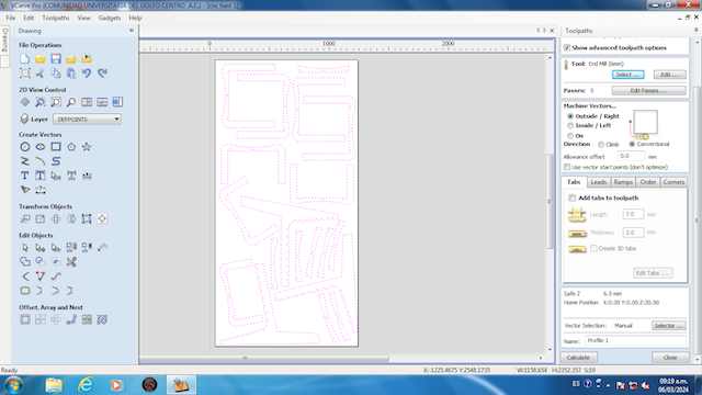
After setting everything up, I pressed "Calculate" to define the toolpath.
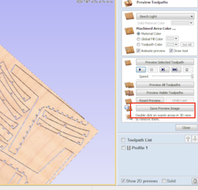
Step 8
I selected the play icon at the highest speed to observe the cutting of the pieces.
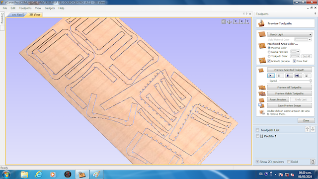
Step 9
Once done, I saved the preview image for reference in the next step.
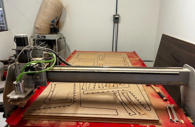
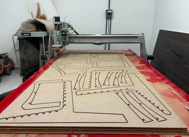
Cutting with Mach 3 CNC Controller:
Step 1
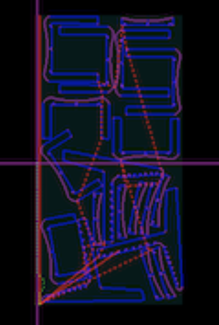
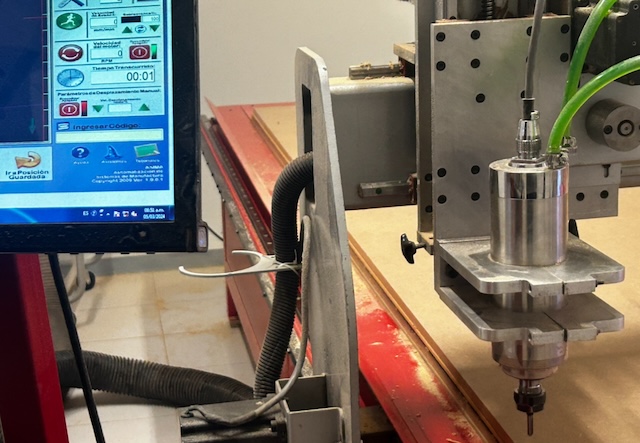
I opened the MACH3 program and imported the previous Vcarve document, which is essentially a G-code, allowing me to visualize the machine's path for the pieces.
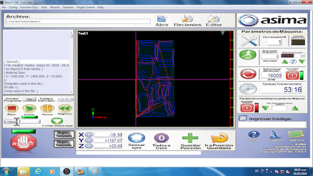
Step 2
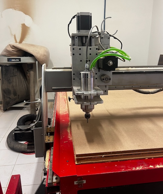
I placed the table on the cutting bed, observing the areas where the machine won't cut, to insert 6 nails that will further secure the board.
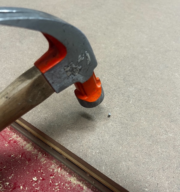
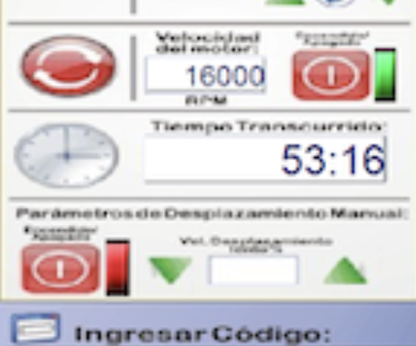
Step 3
I set the spindle speed to 16000 revolutions per minute.The speed of 16000 revolutions per minute was chosen because in practice, our team realized that it cuts with the correct precision, doesn't cause burning, doesn't ruin the design, and everything turns out well.
Step 4
I checked that the router bit was properly adjusted and, using the program's screen, moved the machine head to the upper-right corner, marking the X, Y origin at zero.
Step 5
Lowering slightly in Z, I manually adjusted until the bit touched the table, marking the Z origin.
Step 6
Pressing the run button, I observed the router head lifting first and then starting to spin to avoid issues.
Step 7
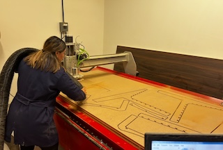
Once ready, I let it perform the cutting while using an extractor to remove the MDF dust.
Step 8
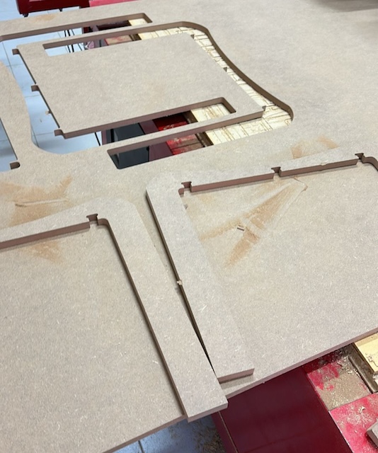
After approximately 2 hours, the process completed. I moved the machine, removed the nails, and took out the pieces.
Step 9
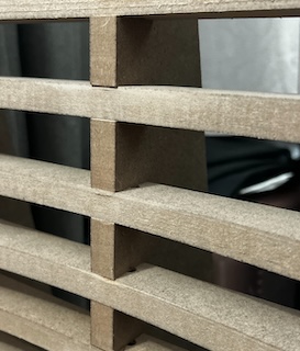
I sanded the added tabs and carefully assembled the piece.
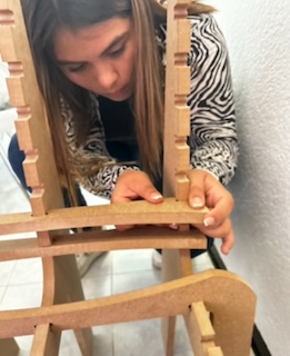
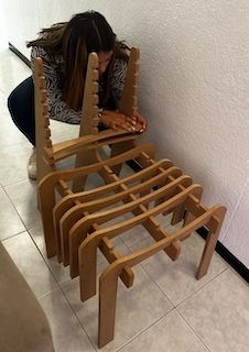
Step 10
This process continued until achieving the final result.