7. Computer-Controlled Machining
First of all, in our group webpage (click here), you will find lab's safety training, some characteristics of the CNC routers that we have in FAB LAB Puebla, materials you may use for this, the Runout test and the design Rules, like dogbones or T-bones, as well as the fixture to avoid possible accidents.
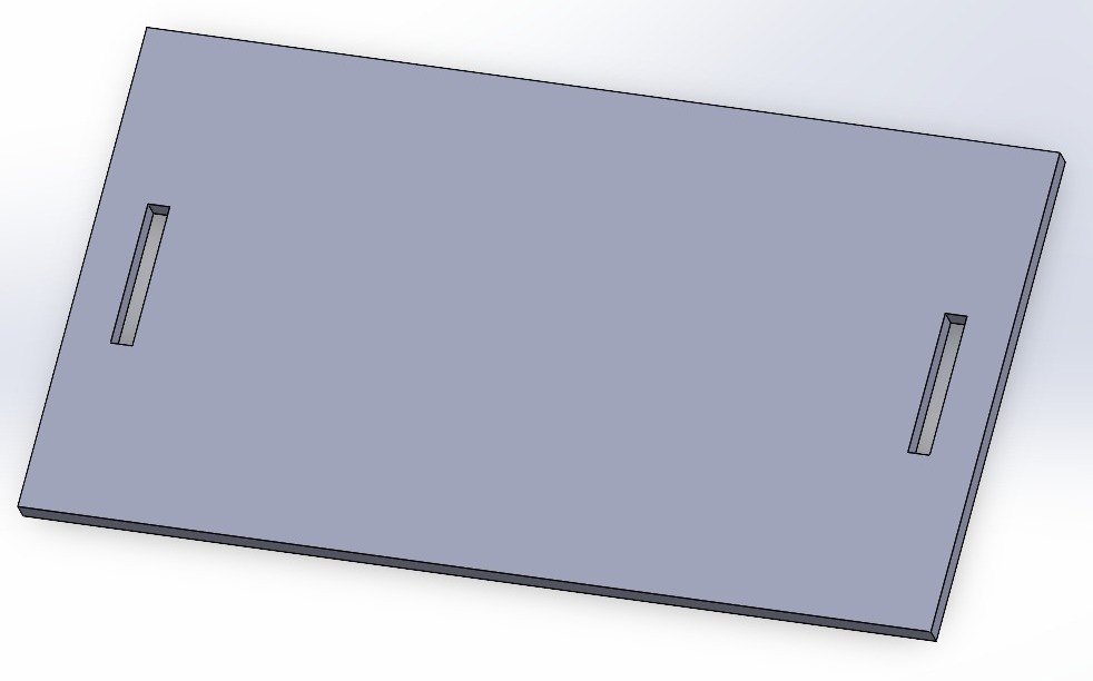
For this assignment, I'm going to use "the MARCH" our generic CNC made by the University, because the interface allows us to see the location of the cross-piece on the cutting area.
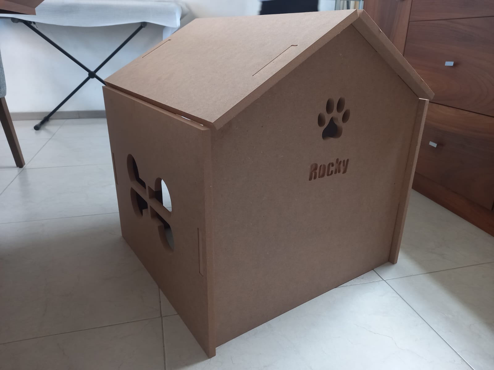
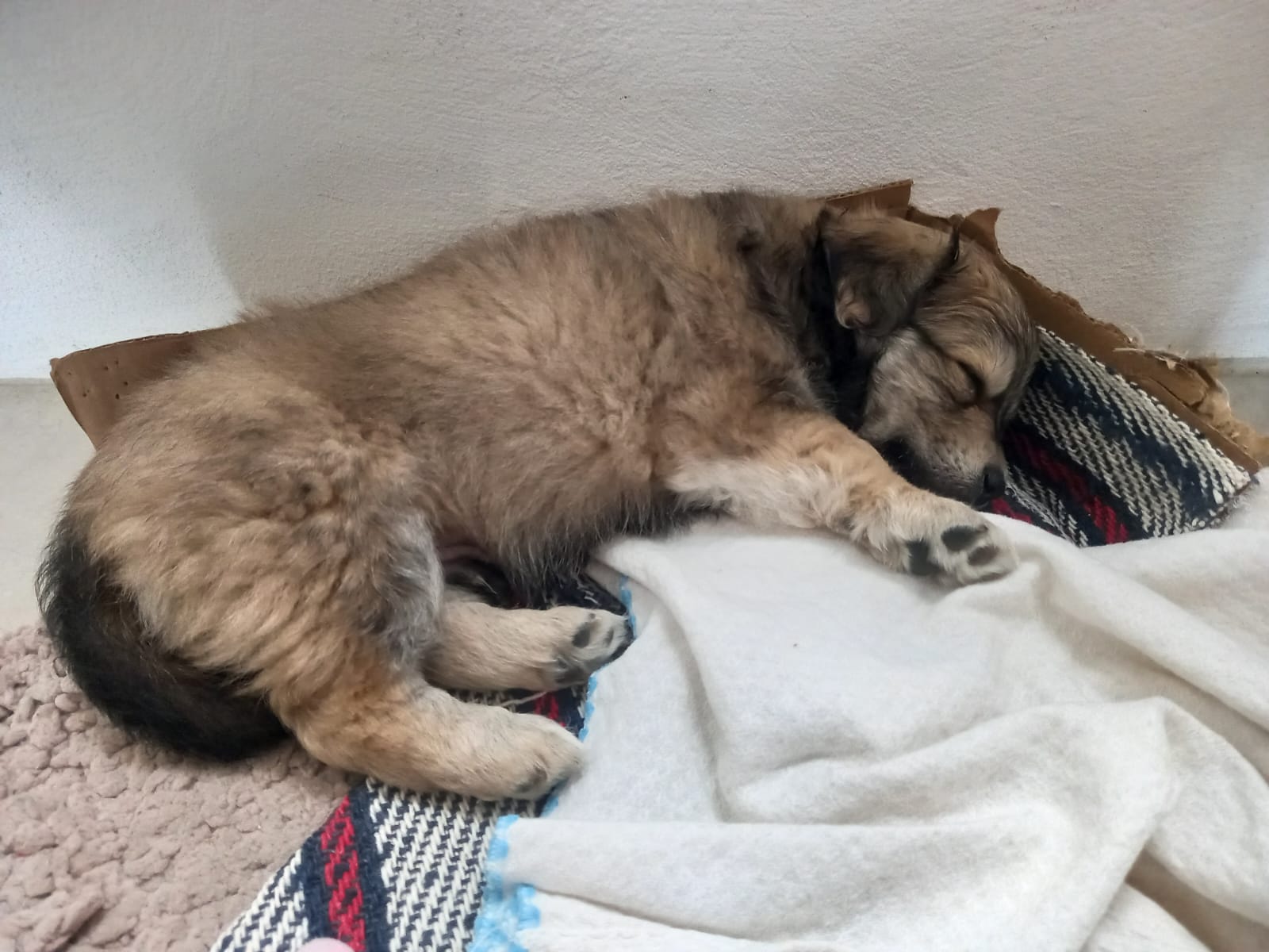
Let me introduce you to the little troublemaker ruling my home: "Rocky." He's on a mission to nibble on everything in the house and has a soft spot for sleeping near us. Right now, he's got a blanket to sleep at night, but I'm thinking it's time to build him a cool little house.
Design
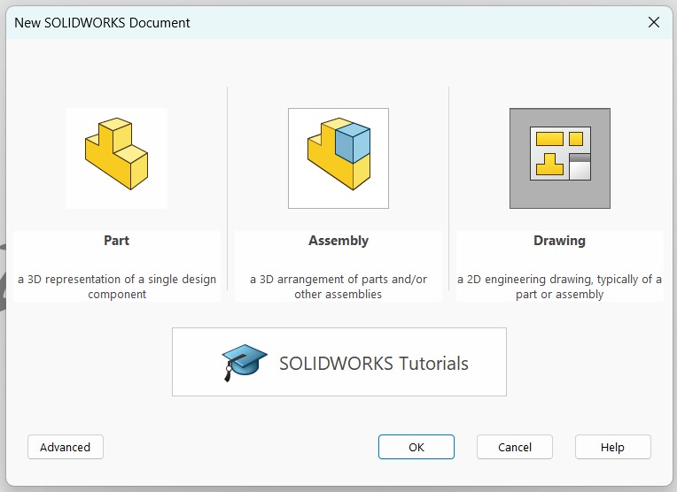
So, I've decided to design this project in SolidWorks.
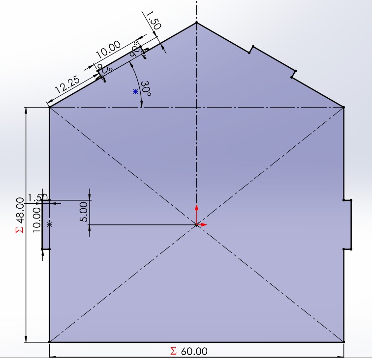
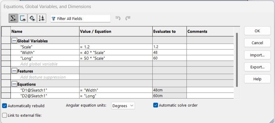
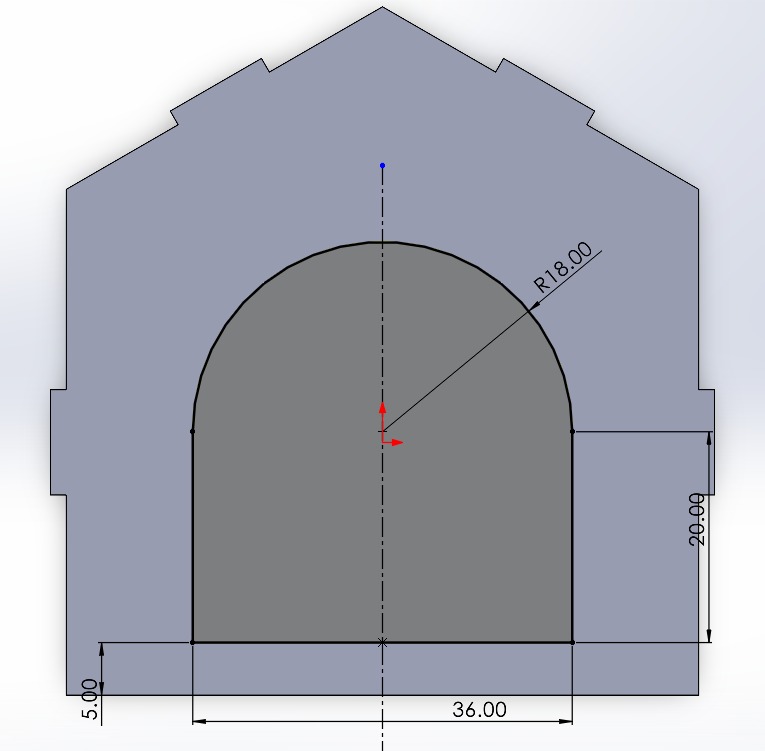
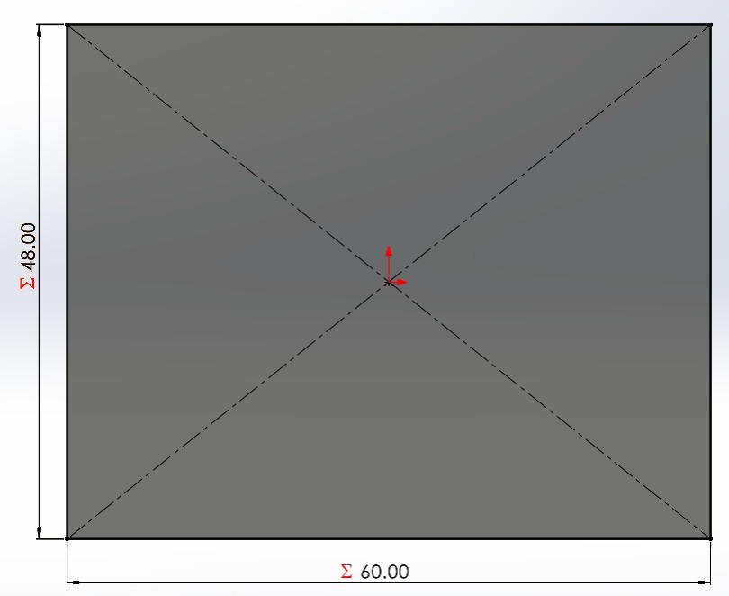
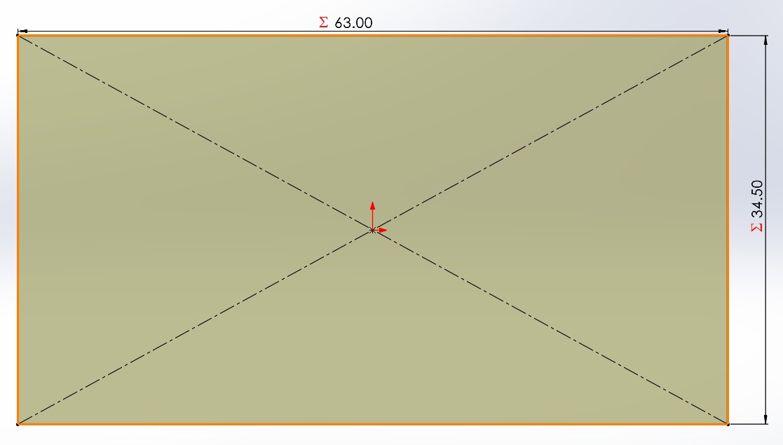
To begin, I measured my dog. When he sleeps on his side, he measures 40 cm on each side. I first made the entrance of the house. I parametrized the entrance sides to easily modify the scale of the house depending on the size of the dog. Each piece has the same equations.
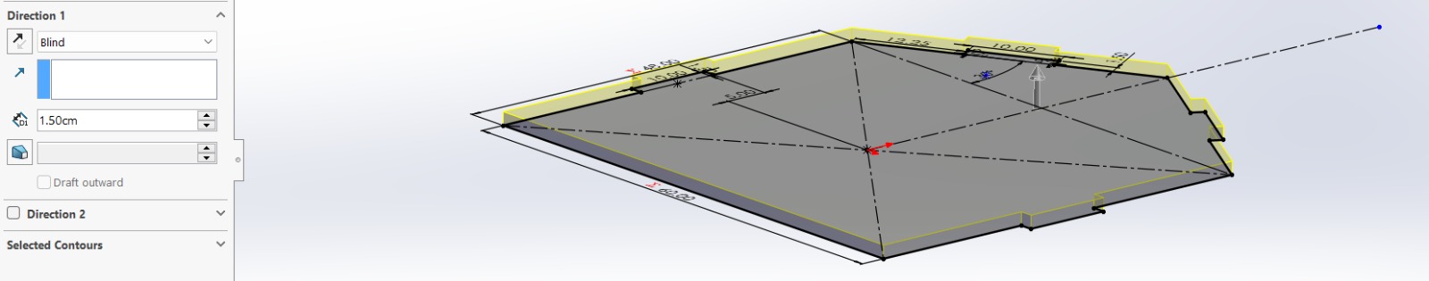
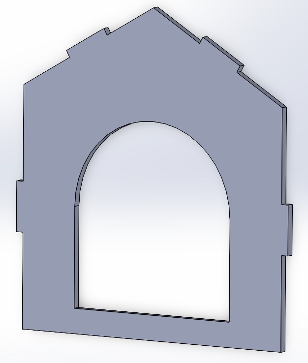
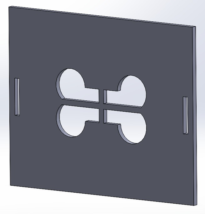
I boss-extruded the shape by 1.5 centimeters because it will be helpful when assembling the entire house.
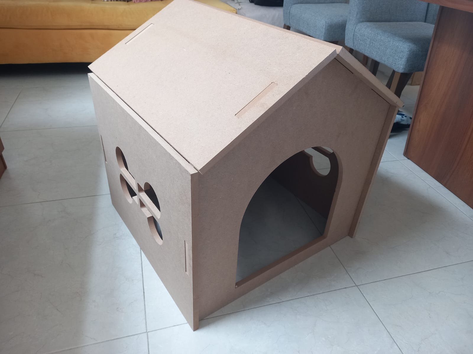
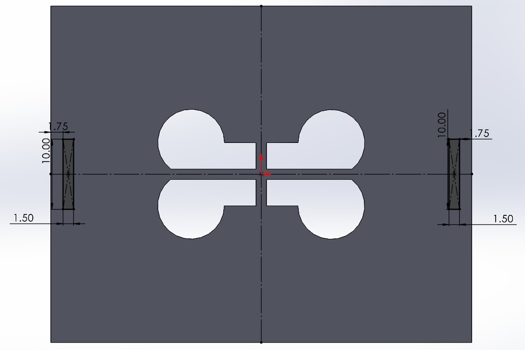
I also drew the door shape before using the cut-extrude feature.
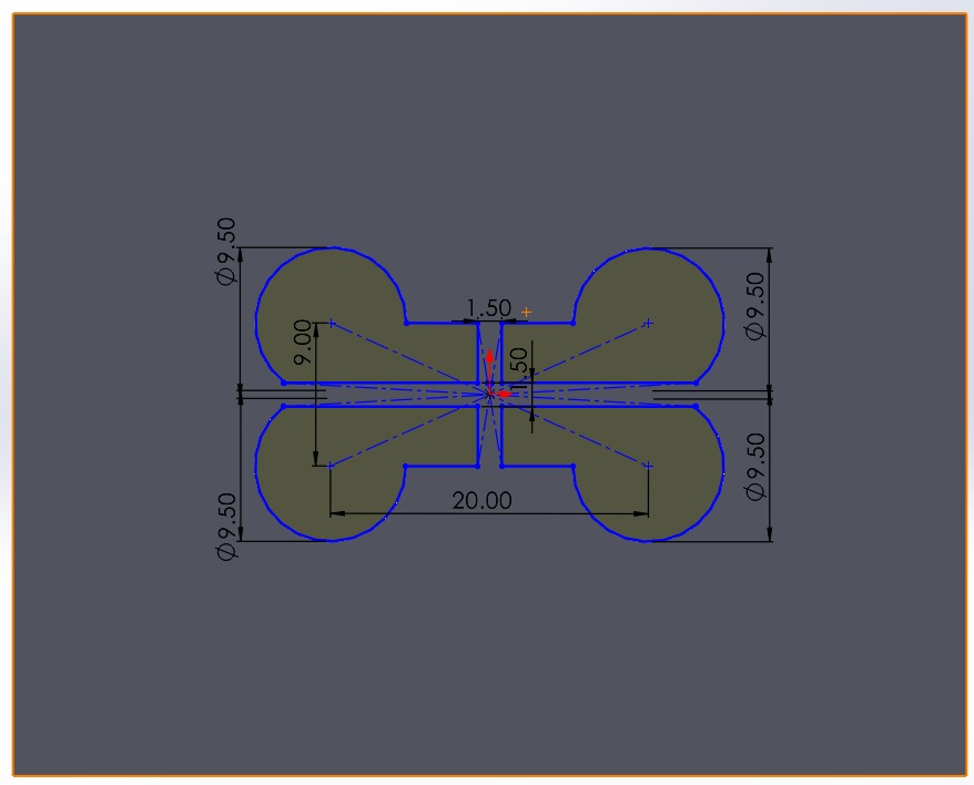
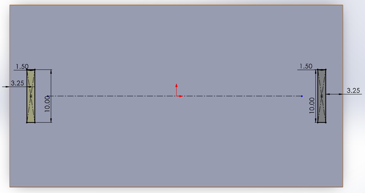
It's important to mention that we sketched the joints, and in the cutting software, we included the T-bones or dog bones. As opposed to the Computer-Controlled Cutting, we don't need to calculate the kerf, that is, the hole and the tab have the same measurements so that they fit perfectly when assembled.
I followed all the previously mentioned steps to sketch the pieces of the house.
Walls
Roof
Back
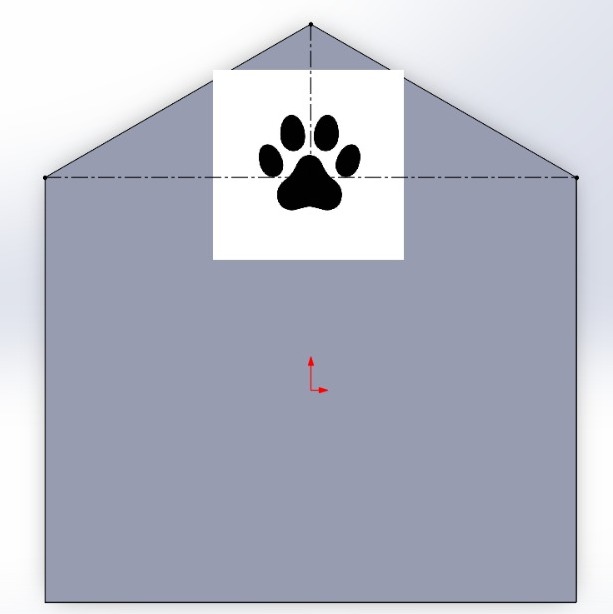
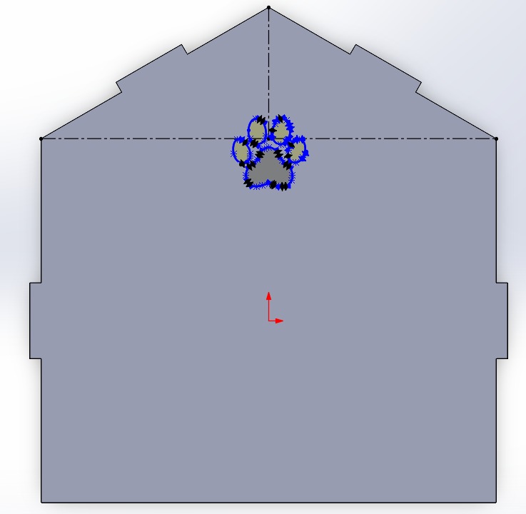
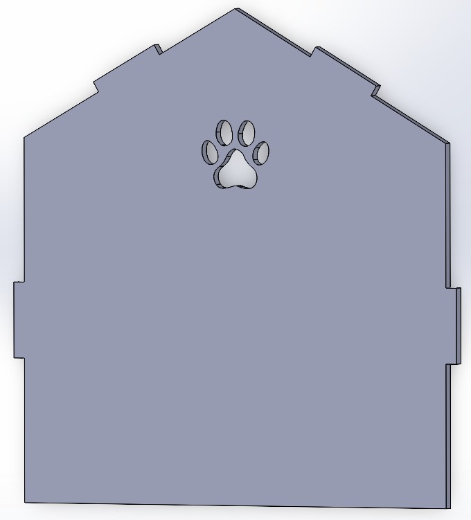
For the back of the house, I copied and pasted the entrance file, and then edited it. I inserted an image of a puppy paw icon and traced the outline using the spline line tool to achieve an organic shape for the cut-extrude feature
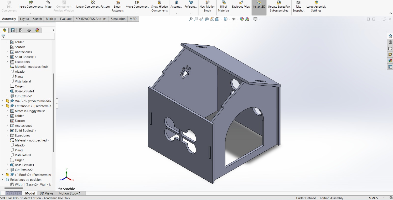
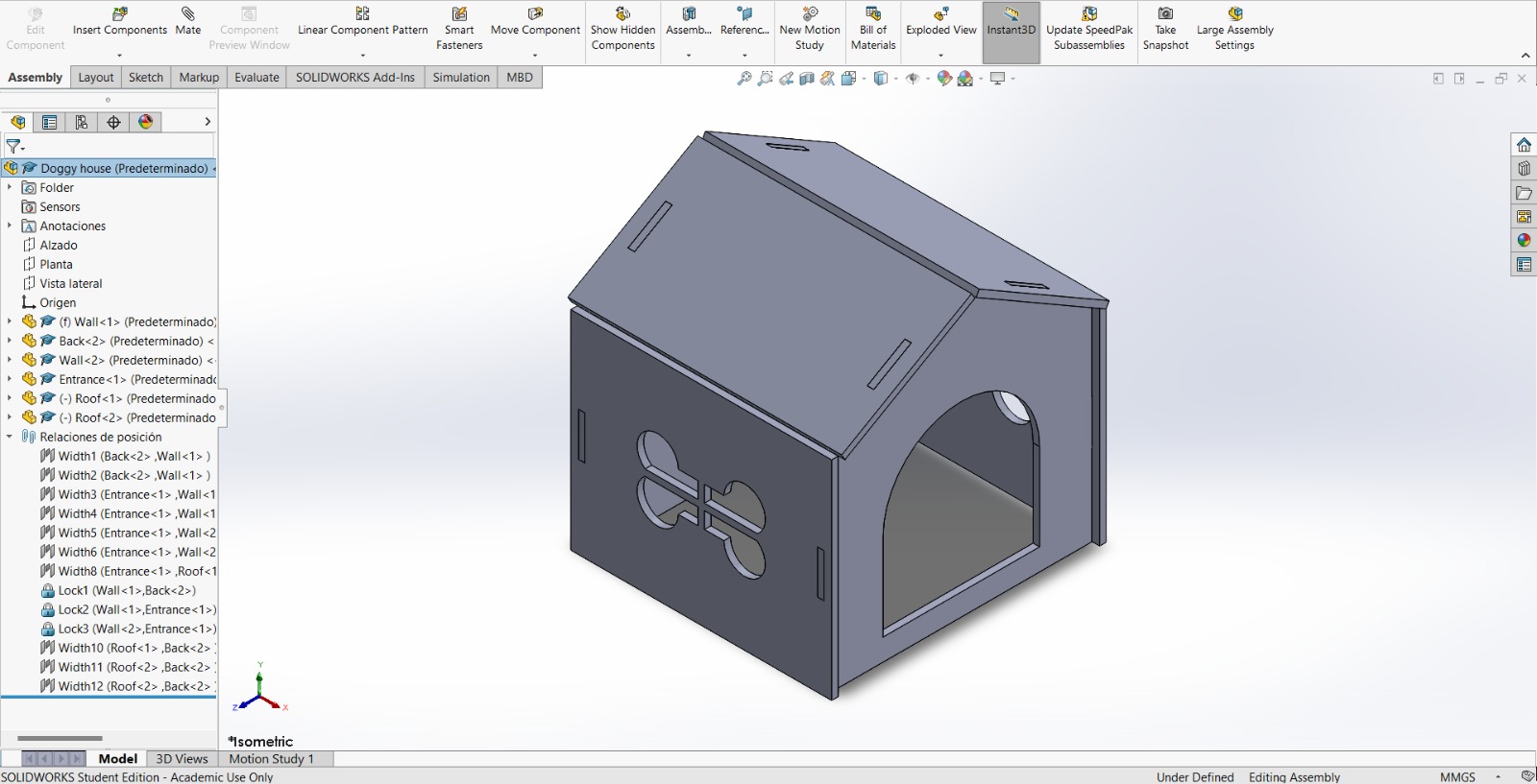
Assembly
My advice is that before cutting, assemble your work. This is crucial to avoid mistakes, incorrect dimensions, and polish your sketches. I noticed that my house had some of these mistakes thanks to this feature.
This is very easy, I started assembling the dog house but there is one piece missing, it's the same principle as the other pieces.
First, insert a component and select your file to assemble.
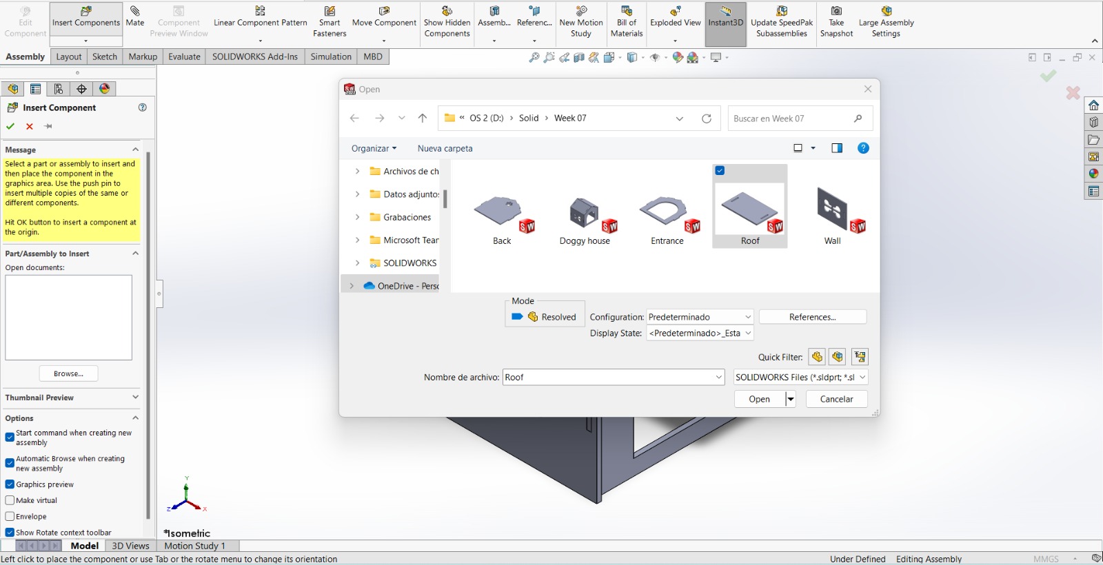
Then, place your piece near the assembly *(My tip).
After that, create a geometric relationship between components. For this click on Mate feature.
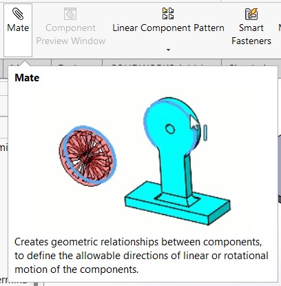
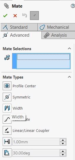
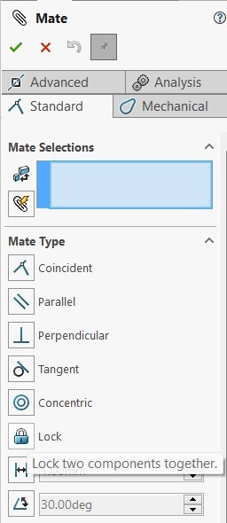
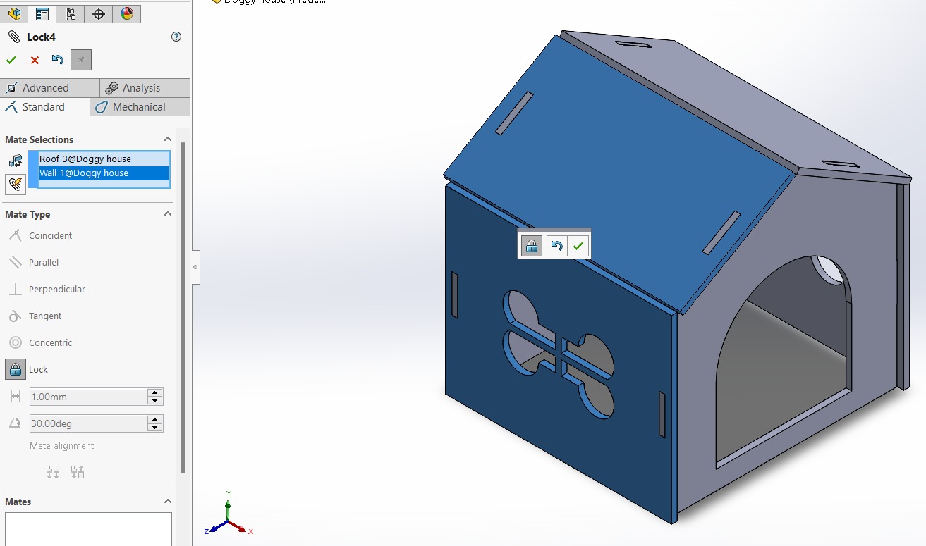
I prefer to use two options: Width (located in the advanced tab) to join two pieces in relation to the faces of each other, and Lock (found in the standard tab) to ensure that once the pieces are joined, they do not move in relation to each other.
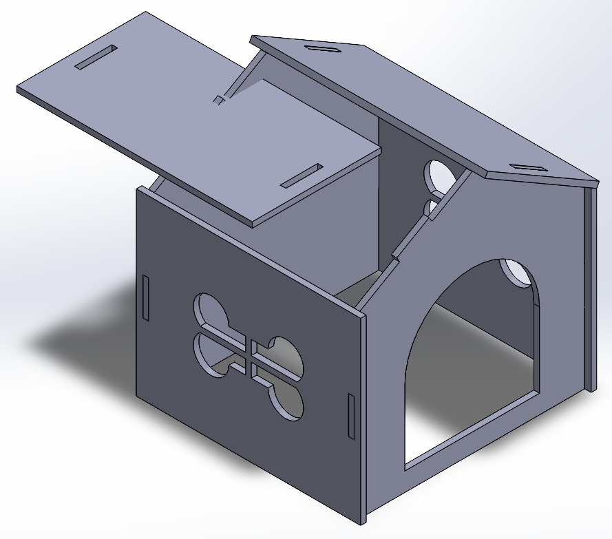
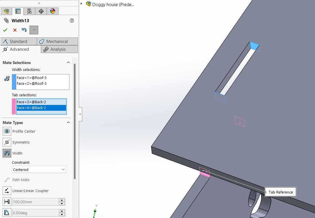
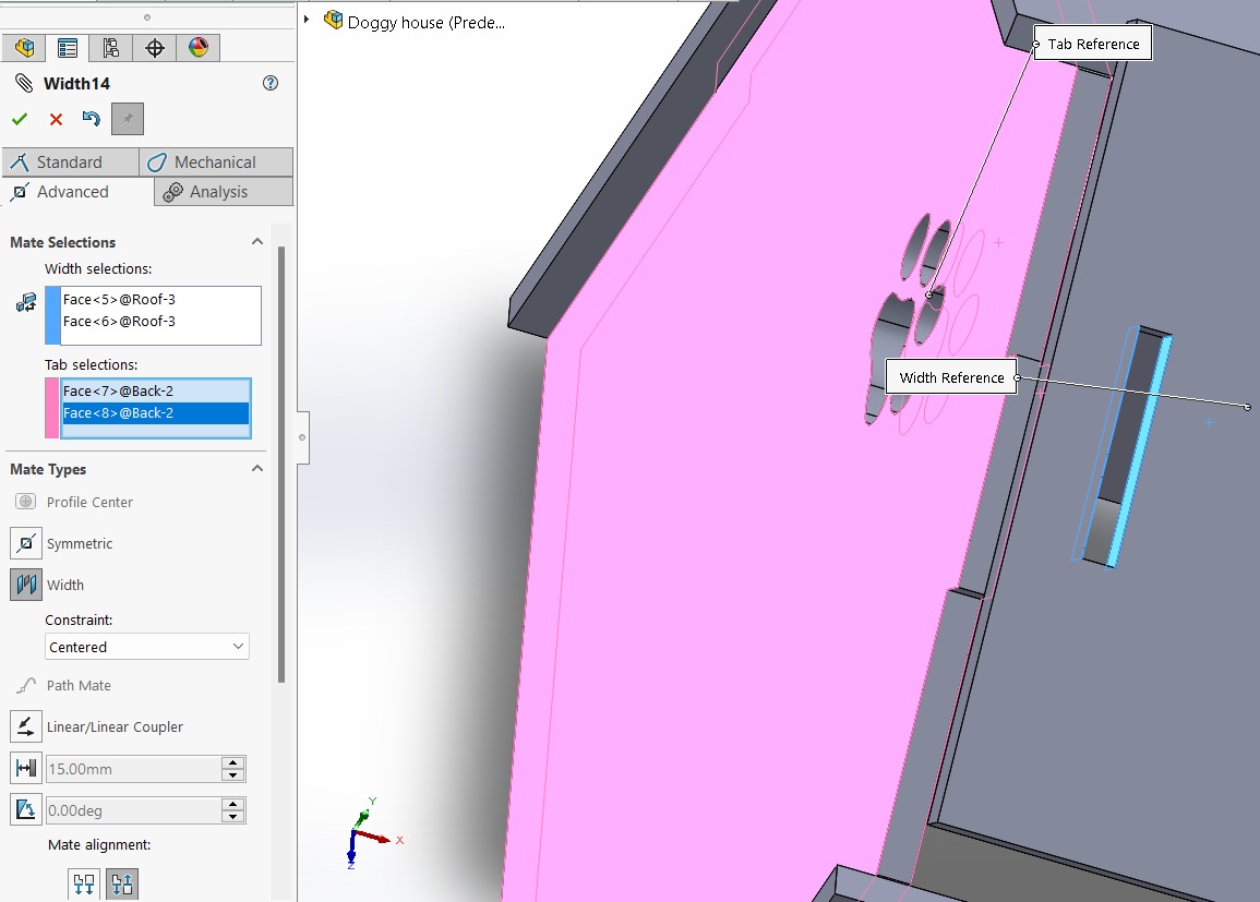
So, I started to use the Width and Lock options. Here there are some examples.
That's our final assembly. Let's go to cut!
CAM-toolpath
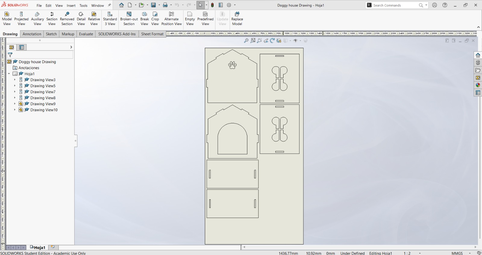
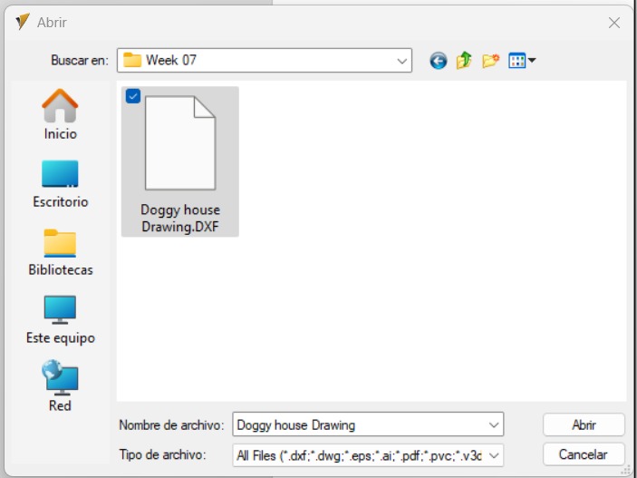
I used the knowledge learned in week 03 to create a DXF file.
Now, open the VCarve software
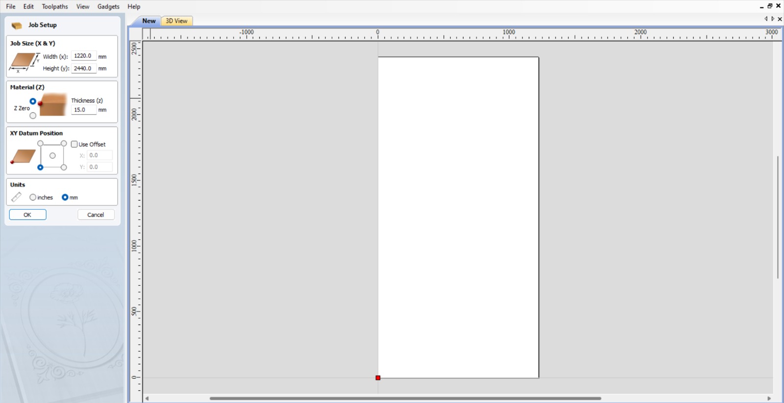
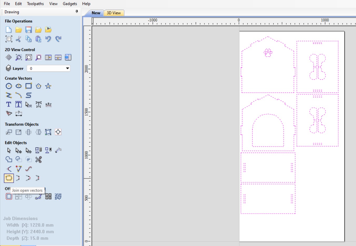
I set up the workspace (Job Setup) and configured the dimensions (Width and Height), thickness, and material units. In my case, it was an MDF table measuring 1220mm (x) x 2440mm (y) with a thickness of 15mm.
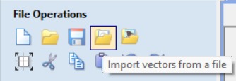
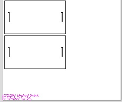
Then import vectors from a DXF file and eliminate the remnants (pink letters).
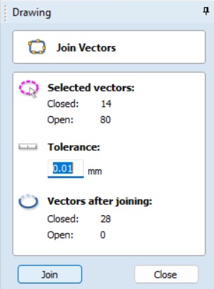
It's SUPER IMPORTANT to select all your vectors and join them; otherwise, the software won't be able to recognize them.
Then, create fillets; these will be the joints. I prefer Dog-bones for my design simply because it goes with a dog theme. Also, the fillet/tool radius will be 3.5 mm.
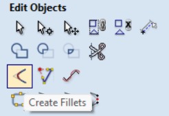 Fille feature.
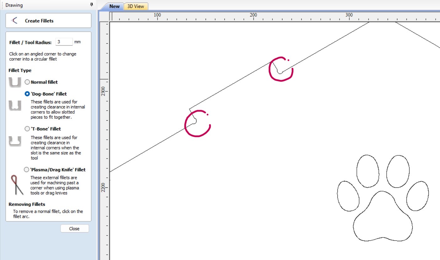 Corner fillet for the tabs.
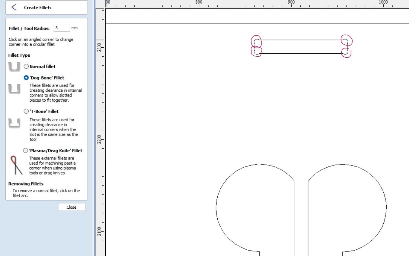 Inside corner fillet for the joints.
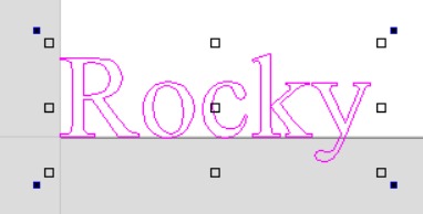
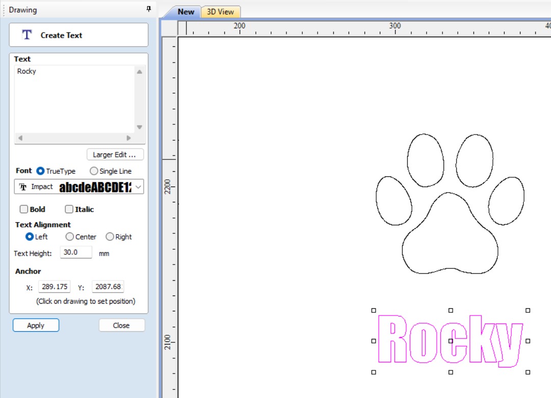
I want the name of my dog in the house. So, I used the tool to draw text.
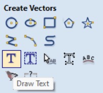
 Double-click to move the text box.
Place it wherever you want and use the text tools to modify the font, size, and others. I used Impact font with 30 mm of text height
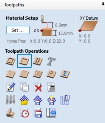
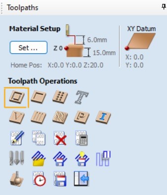
I have already prepared the file to do the CAM-toolpath. On the right we can find the toolpaths, select Pocket
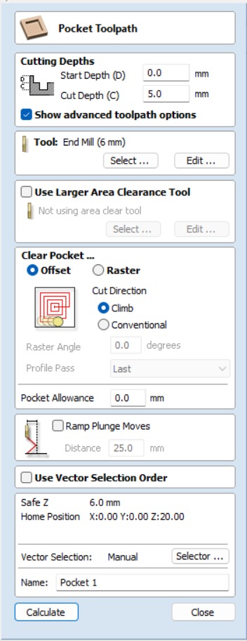
Here, set the following:
- Cutting Depths: Start 0 mm and Cut 5 mm.
- Clear Porcket: Offset and climb.
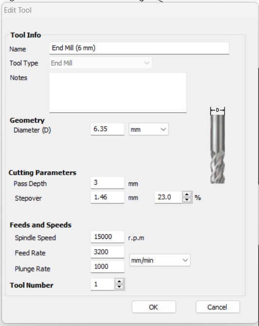
As well, edit the tool:
- Name:End mill (6 mm).
- Geometry Diameter 6.35 mm.
- Cutting Parameters Pass Depth 3 mm and stepover 1.46 mm or 23%.
- Feeds and Speeds Spindle speed 15000 r.p.m.; Feed rate 3200 and Plunge rate 1000. All in mm/min.
- Diameter 6.35 mm.
After that, select all the inside cuts and the 2D profile toolpath.
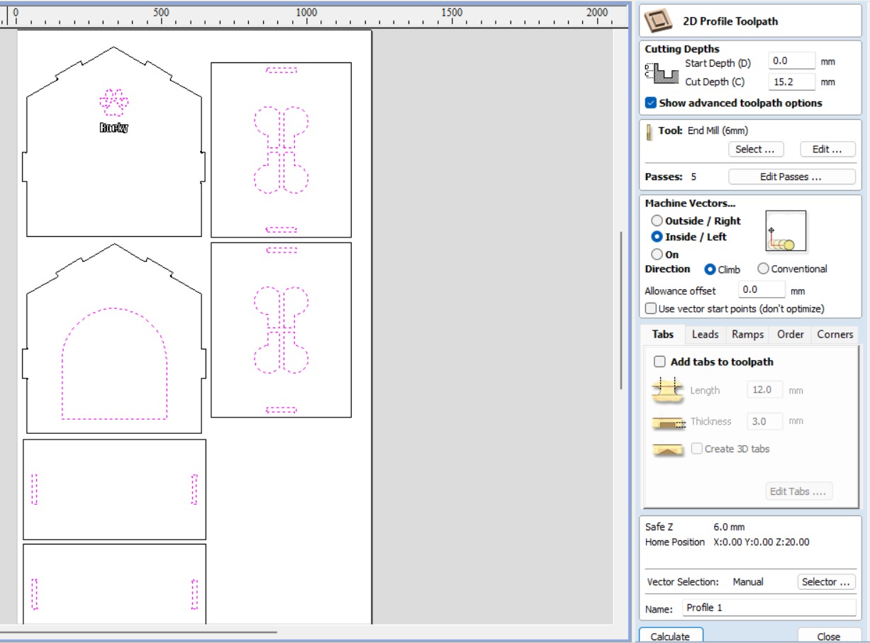
Here, set the following to calculate:
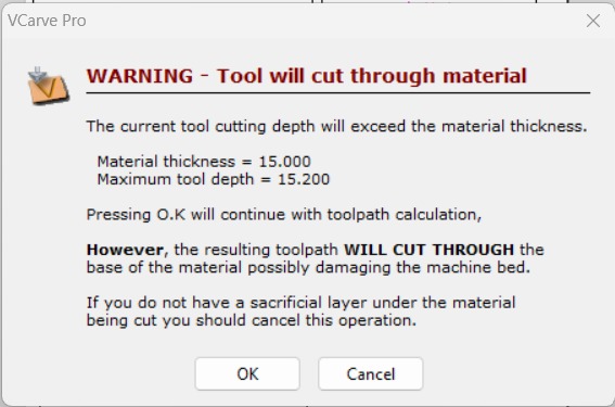
- Cutting Depths: Start 0 mm and Cut 15.2 mm.
- The same tool, in other words, I don't change the tool.
- Machine vectors: Inside/Left.
A warning will pop up, but don't worry; it's okay. We'll explain why later.
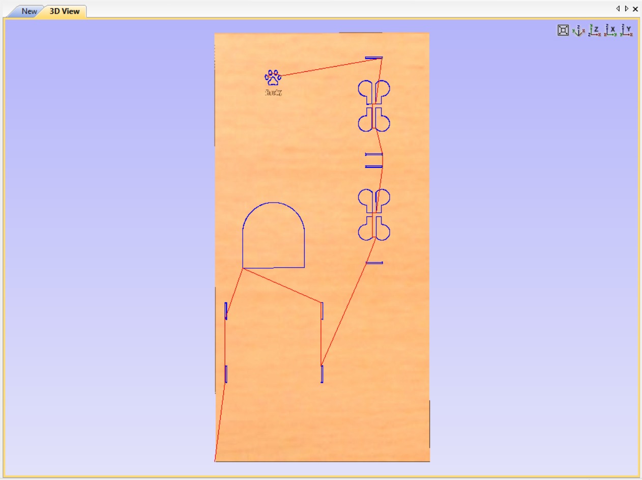
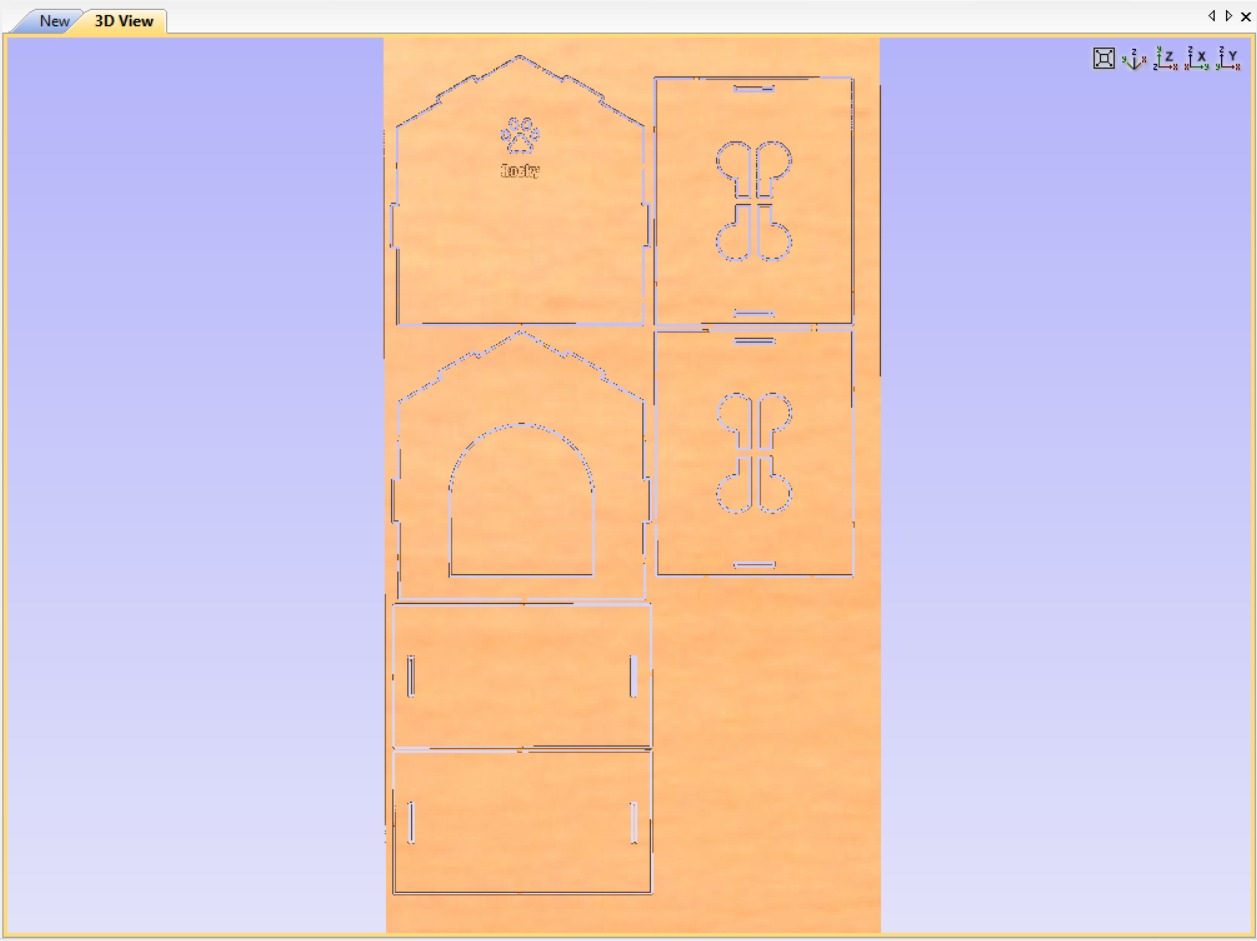
The software will show you a preview of your toolpaths. Here, just have the Pocket and Inside Profile.
The last one is the outside profile. A helpful tip: if you find yourself still having selected the inside profiles and then select all your vectors, the selection will automatically invert to include the remaining lines that aren't selected.
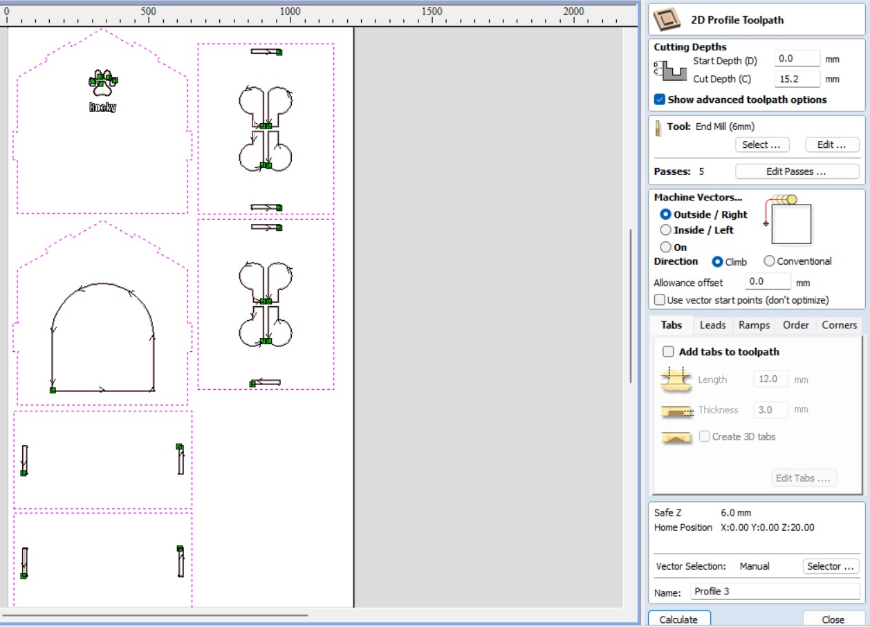
Here, set the following to calculate:
- Cutting Depths: Start 0 mm and Cut 15.2 mm.
- The same tool, in other words, I don't change the tool.
- Machine vectors: Outside/Right!!
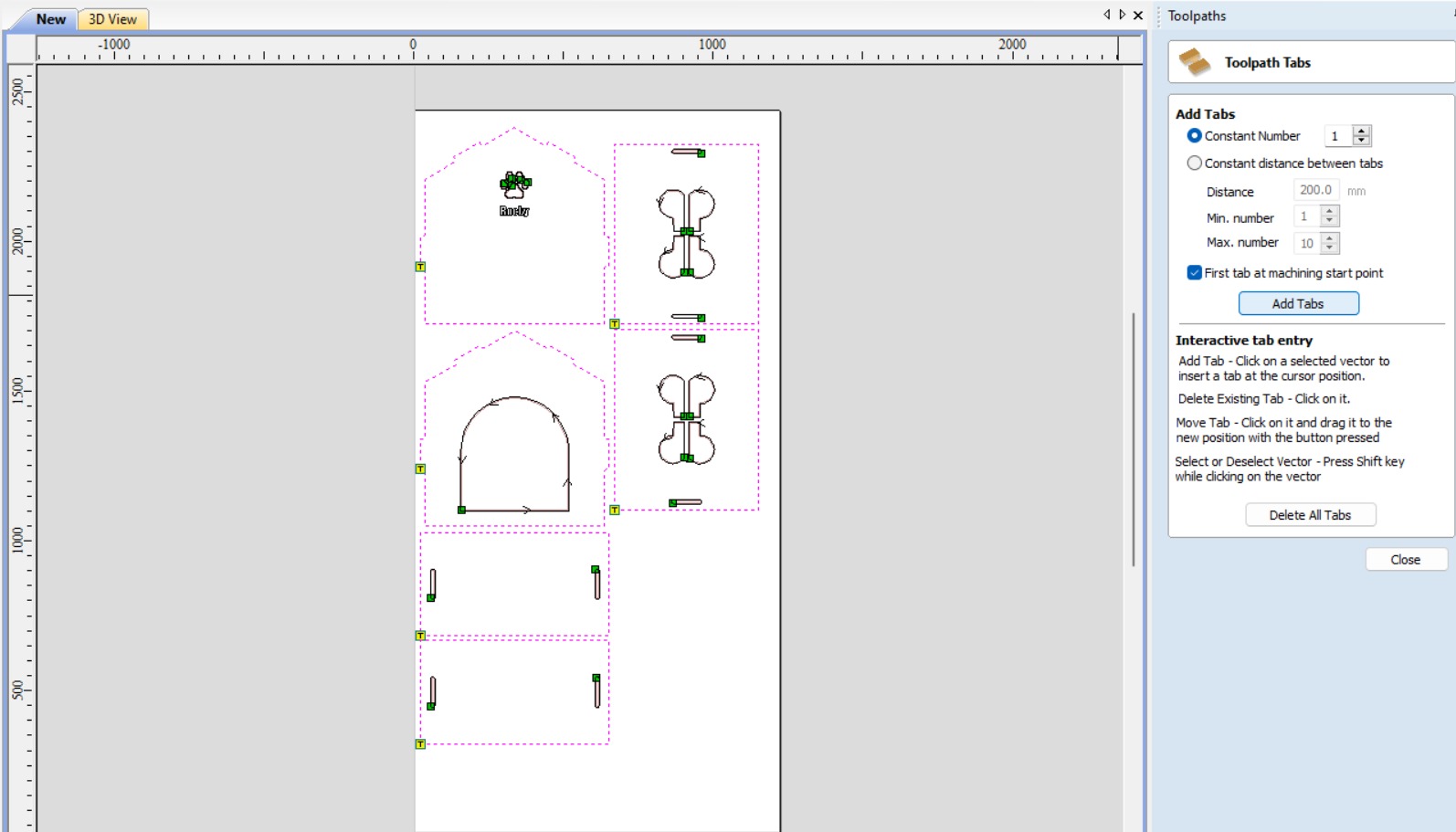
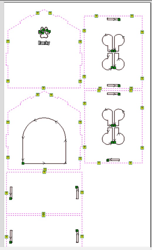
- Add tabs and edit them.
The software will include tabs by default, but I prefer to choose where to place them. You can click wherever you want to add a tab and click on the same tab again to remove it.
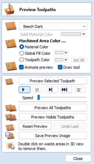
Perfect! We have all the toolpaths ready to save the file. However, it's crucial to click Start in the preview all toolpaths. This allows us to simulate the cutting process and check if everything is okay before proceeding machining cut.
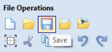
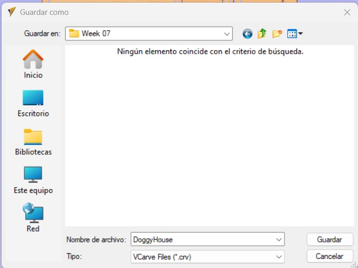
Finally, save the file.crv to your device.
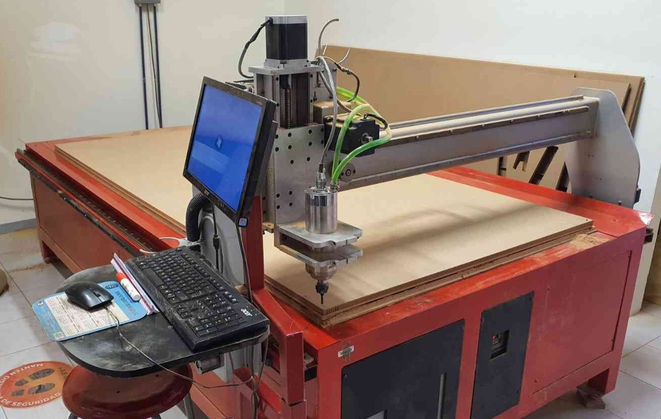
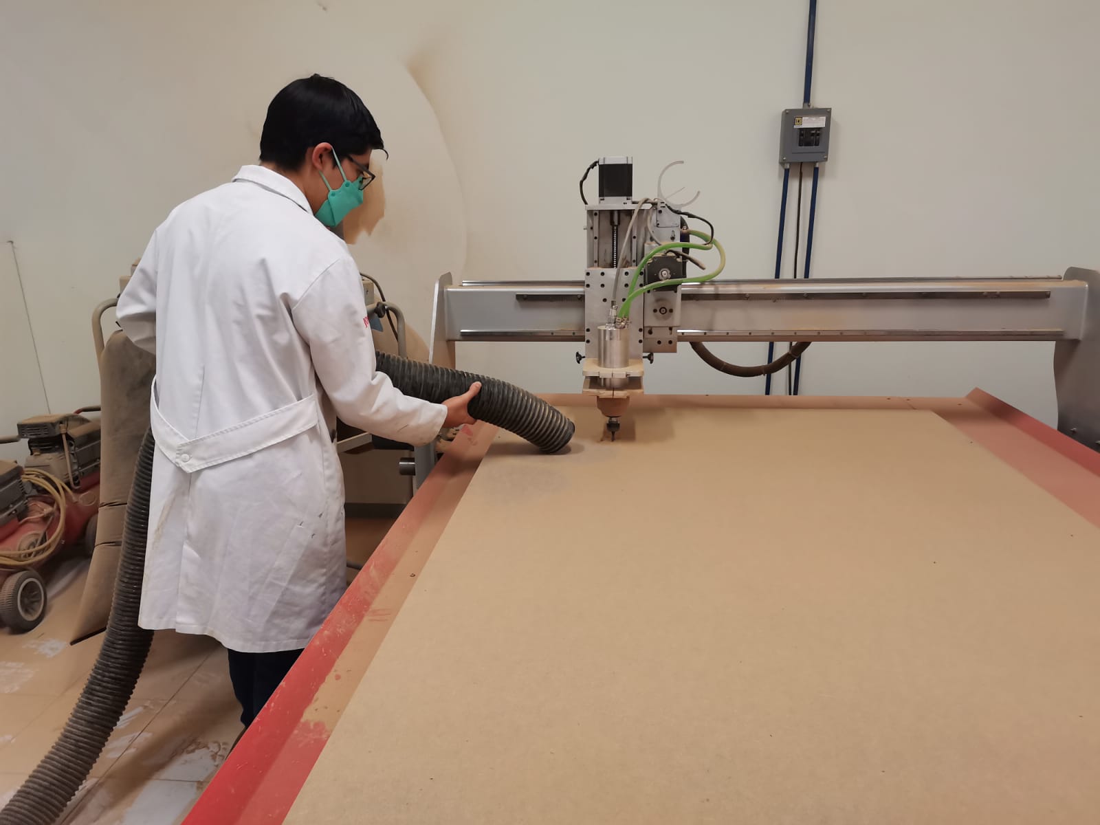
Machining cut
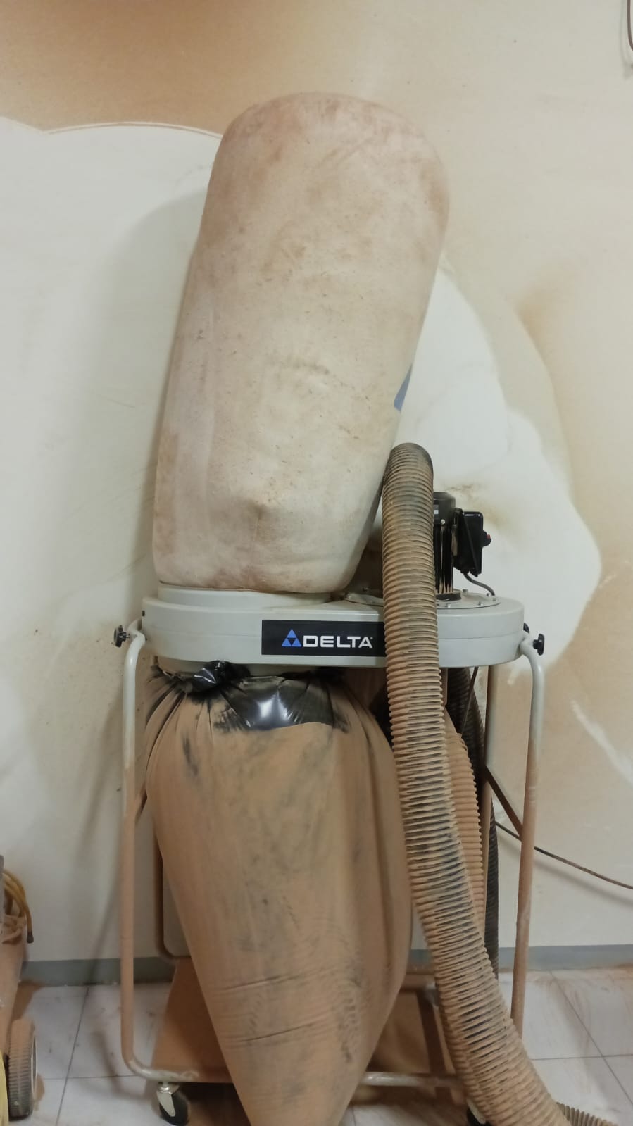
At FABLab Puebla we have The Mach 3 (CNC) and the extractor. Both have a red switch on the side to turn on.
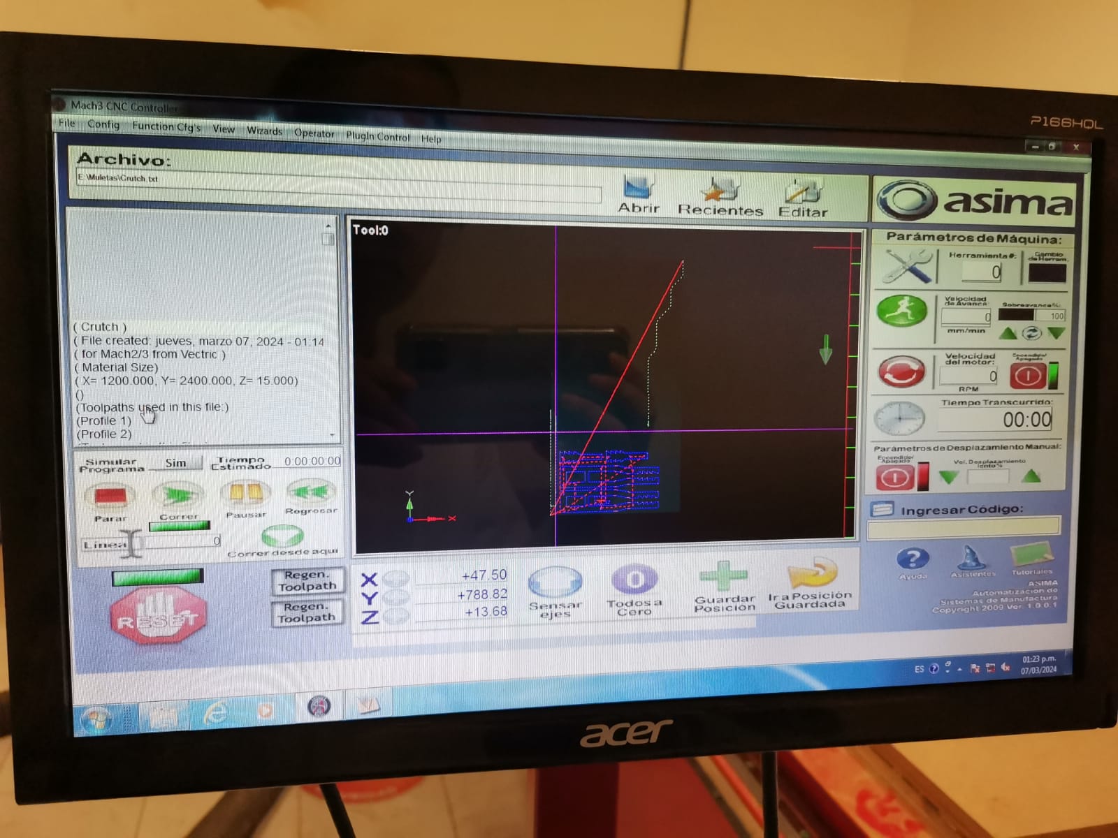
Open the Mach3 app and load the VCarve file.
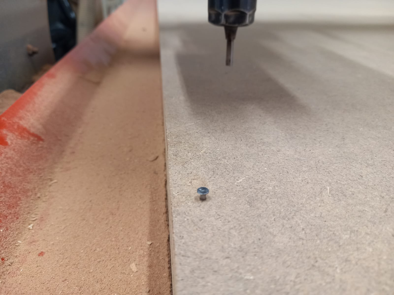
Secure the MDF board to the table using nails, ensuring they are placed in an area where the cutting tool won't pass.
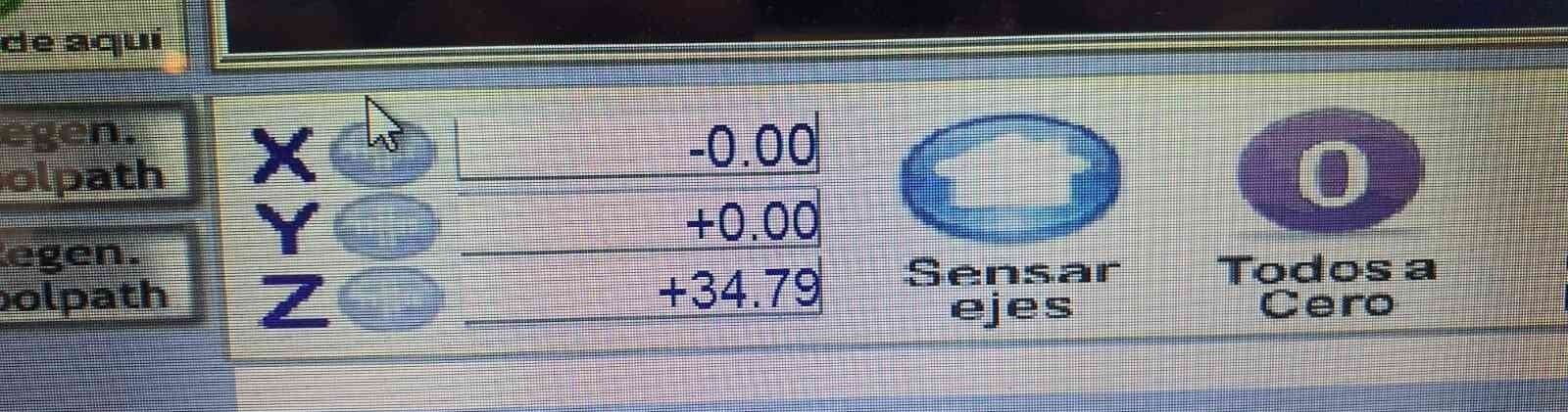
To position the tool in the corner along the x and y axis, use the keyboard arrows. Utilize Re Pag(Page up) and Av Pag (Page Down) to move along the z axis or rotate the tool axis. Press Shift key to move faster. Set your coordinates clicking on the buttons.
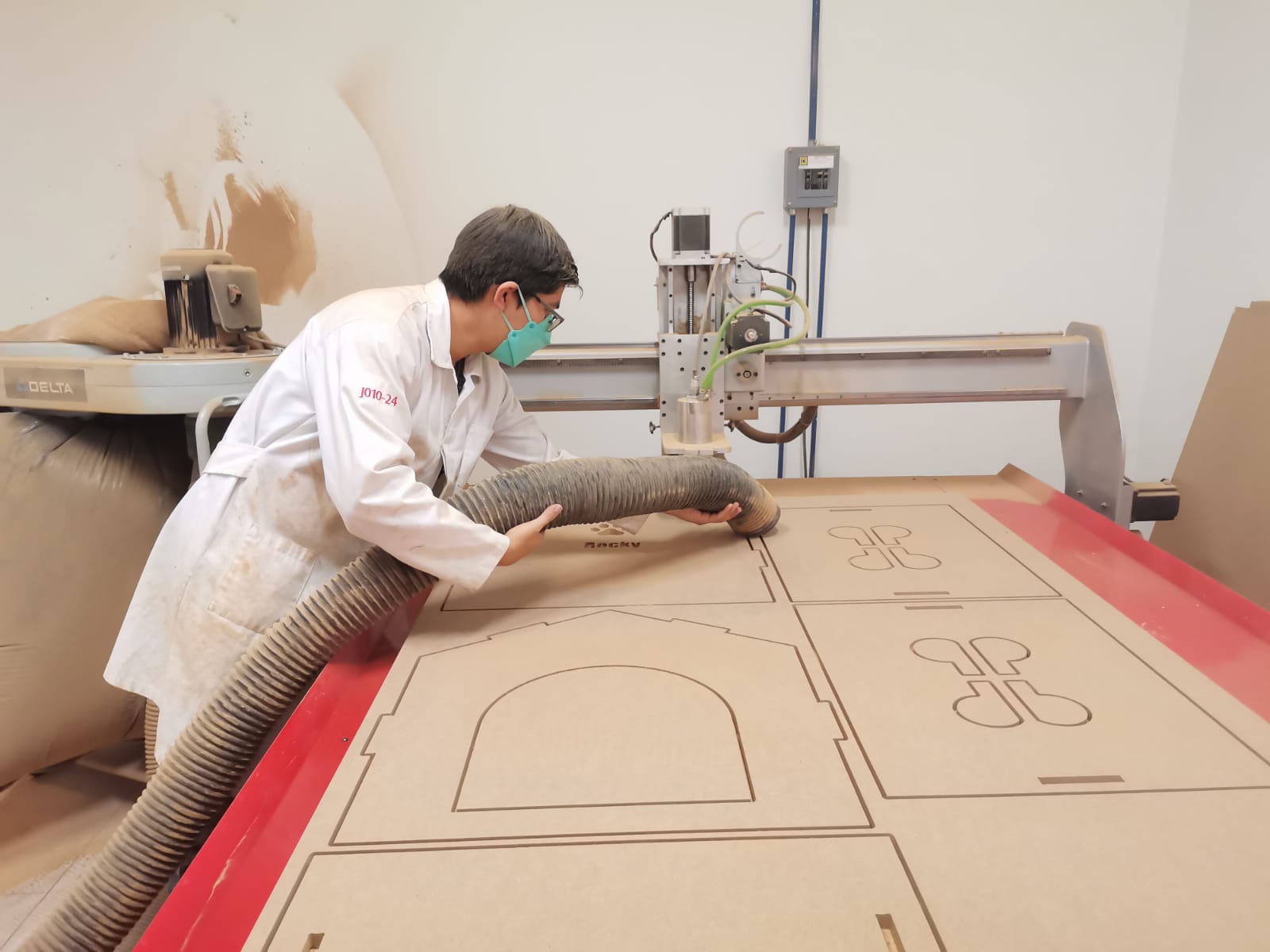
And click on Start/Correr. Don't forget to collect the sawdust.
Assembly
My dad wanted to help me because he was excited since he loves so much or dog.
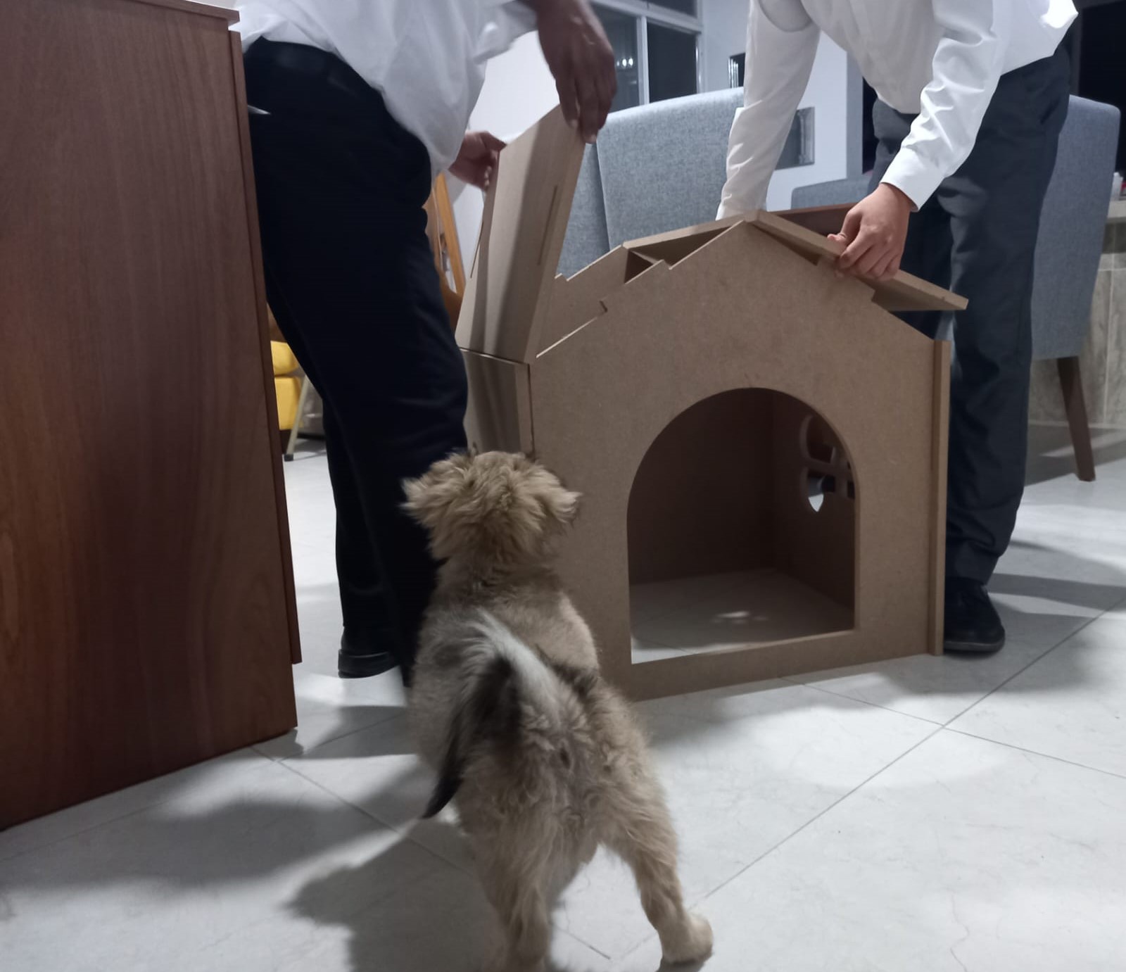
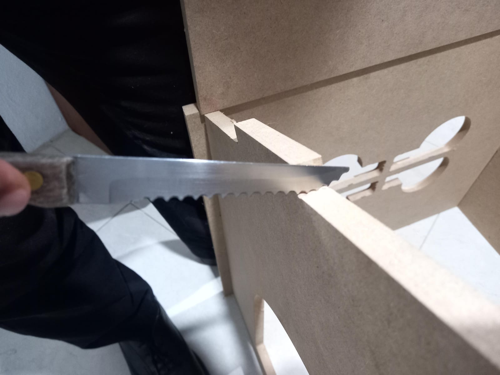
It was easy to assemble but we had a problem, I forgot a Dog-Bone so we used a saw knife to cut a corner of 90°.
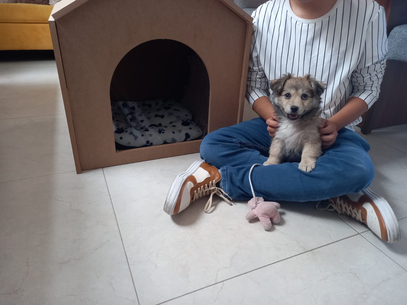
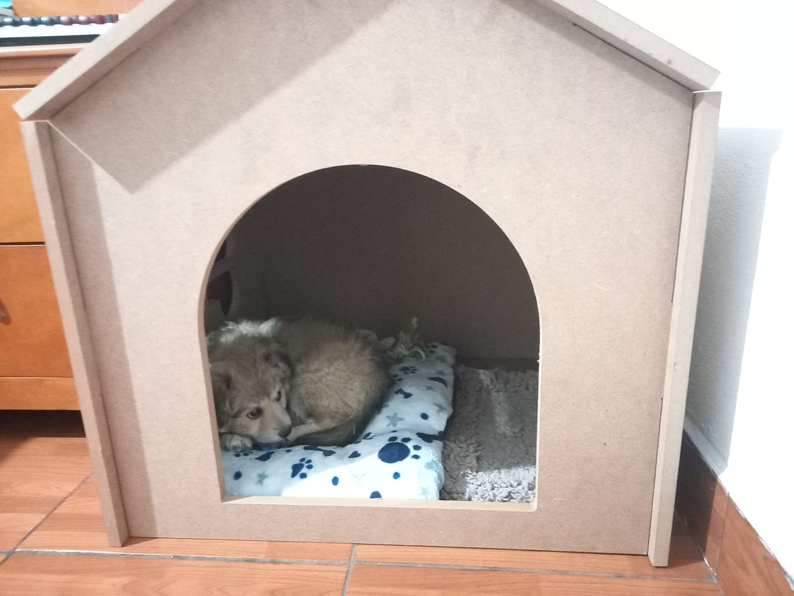
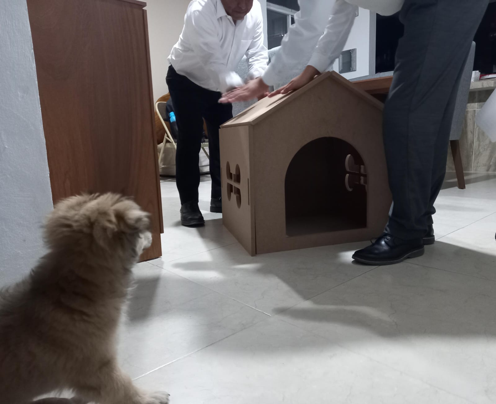
Happy Doggy