Input devices
Let´s to control the signals
TO START
Click here to see the group assigment
For this assignment I designed a new pcb, with the intention of exploring the possibilities of INPUTs and OUTPUTs. So, I decided to work again with the XIAO RP 2040 microcontroller to include a series of components that would be useful for both exercises.
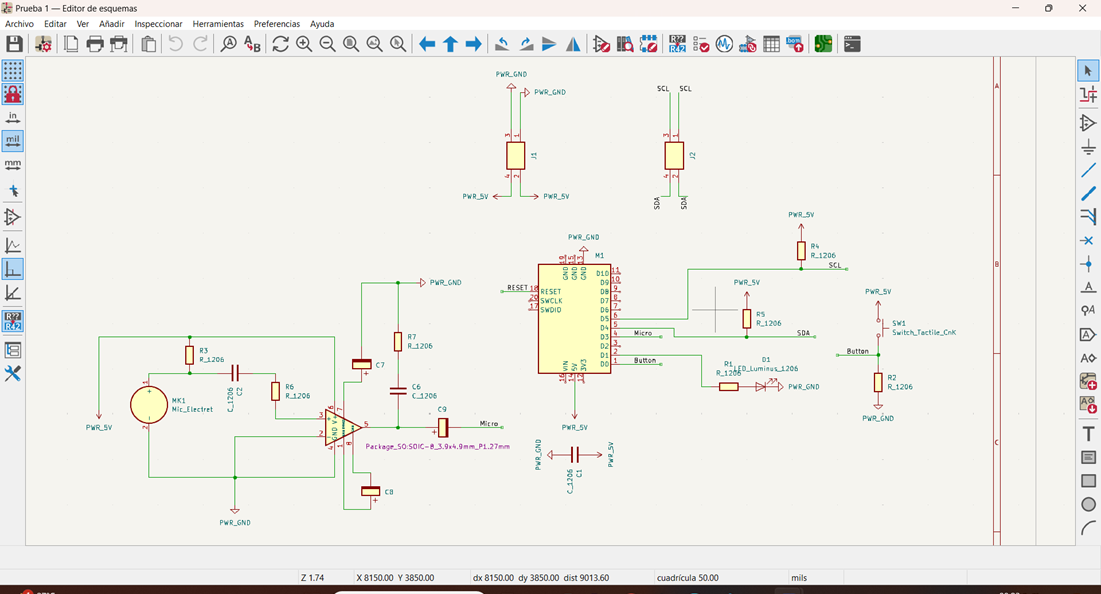
- An LED and its respective 1K resistor
- 1 Capacitor
- 2 sets of 4 pins for I2C communication (suggestion from my instructor)
Noise Sensor I decided to include the noise receiving system on the same pcb, so I added these components:
- An electret microphone
- A potentiometer
- Capacitor 0.1 uF
- 10K resistance
- LM386 amplifier
- 2 10uF Capacitors
- A 0.047 uF capacitor
- A 100 uF capacitor
- A 10 ohm resistor
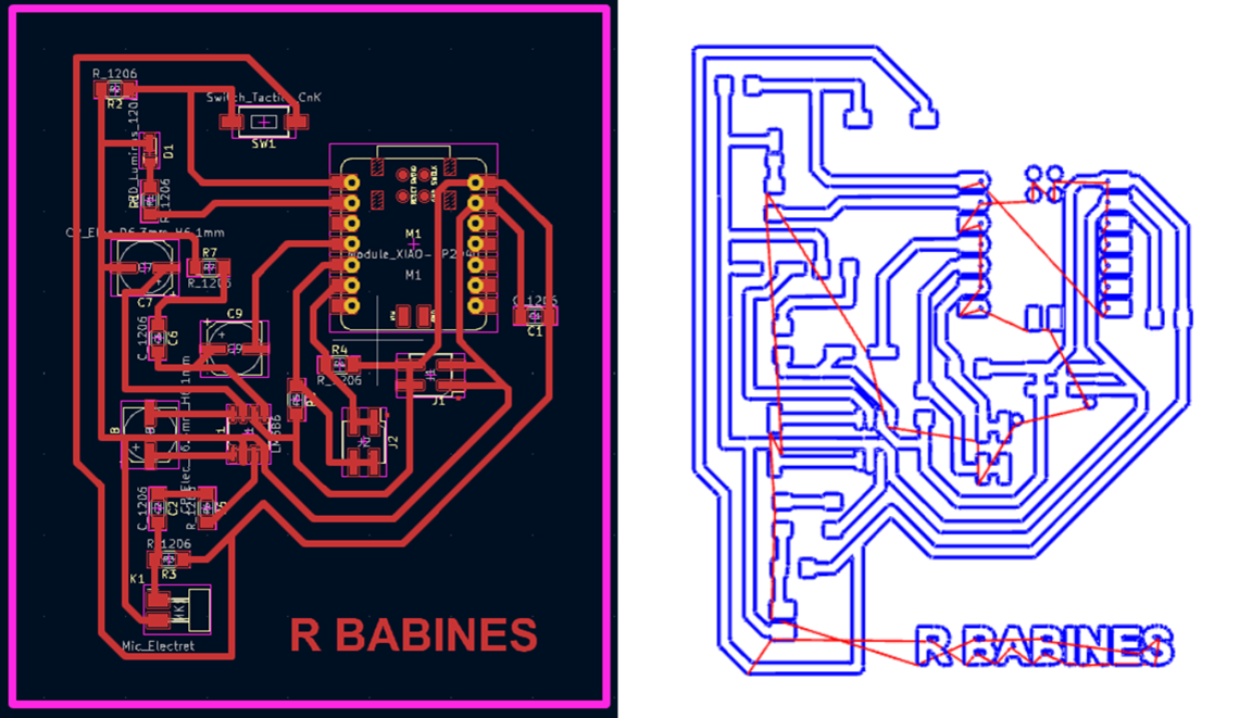
Track configuration
My big mistake
While I was connecting the tracks I noticed that the figure was very similar to the letter R, so I decided to change the arrangement of all the components so that the pcb would be cut with that shape, but, in the process I forgot to connect 2 components, like this that I had to repeat the process but this time, with less creativity and more objectivity.
Settings in Mods
The same process from Week 4

This is what the PCB looks like after soldering all the components.
Now, we´re ready to program
Click here to download design files
Press, Tap, Pulse or whatever you want
How to move one servomotor with a button
I used Arduino to program the microcontroller and connected 2 Servo Motors to the Analog Pins.
The goal in the first exercise was to activate the servo movement when you press the button and stop the loop when you press the button again.
Click to download code
	#include Servo.h // Servo.h entre los signos de menor que y mayor que

		Servo Raul1;
		Servo Raul2;

		int servoPin1 = D6;   // Pin D6 para el primer servo
		int servoPin2 = D2;   // Pin D2 para el segundo servo
		int ledPin = D1;      // Pin D1 para el LED
		int botonPin = D0;    // Pin D0 para el botón

		bool servosActivos = false;
		bool botonPresionado = false;
		bool ultimoEstadoBoton = false;

		void setup() {
		  pinMode(ledPin, OUTPUT);
		  pinMode(botonPin, INPUT_PULLUP);  // Habilitar resistor de pull-up interno para el botón
		  Raul1.attach(servoPin1);
		  Raul2.attach(servoPin2);

		  // Iniciar la comunicación Serial
		  Serial.begin(9600);
		}

		void loop() {
		  // Leer el estado actual del botón
		  bool estadoBoton = digitalRead(botonPin);

		  // Detectar transición de no presionado a presionado
		  if (estadoBoton != ultimoEstadoBoton) {
			delay(50);  // Debounce: esperar un poco para estabilizar la lectura del botón
			estadoBoton = digitalRead(botonPin);  // Leer nuevamente el estado del botón después del debounce
			if (estadoBoton != ultimoEstadoBoton) {
			  // Cambio de estado detectado
			  if (estadoBoton == LOW) {
				// Botón presionado
				botonPresionado = true;
			  }
			  ultimoEstadoBoton = estadoBoton;  // Actualizar el último estado del botón
			}
		  }

		  // Manejo del estado del botón
		  if (botonPresionado) {
			// Cambiar el estado de los servos y el LED solo si el botón ha sido presionado y soltado
			if (!servosActivos) {
			  // Iniciar el movimiento de los servos y encender el LED
			  digitalWrite(ledPin, HIGH);
			  servosActivos = true;
			  while (estadoBoton == LOW) {
				Raul1.write(180);   // Ajustar aquí la posición deseada para Raul1
				Raul2.write(180);   // Ajustar aquí la posición deseada para Raul2
				delay(800);         // Retraso entre movimientos (ajustar según sea necesario)
				Raul1.write(0);     // Ajustar aquí la posición inicial deseada para Raul1
				Raul2.write(0);     // Ajustar aquí la posición inicial deseada para Raul2
				delay(800);         // Retraso entre movimientos (ajustar según sea necesario)
				estadoBoton = digitalRead(botonPin);  // Actualizar el estado del botón
			  }
			} else {
			  // Detener el movimiento de los servos y apagar el LED
			  digitalWrite(ledPin, LOW);
			  Raul1.write(0);   // Ajustar aquí la posición de reposo deseada para Raul1
			  Raul2.write(0);   // Ajustar aquí la posición de reposo deseada para Raul2
			  servosActivos = false;
			}
			botonPresionado = false;  // Reiniciar la bandera de botón presionado
		  }
		}
The power of John Mayer
New light always makes me dance
In the second exercise I used the microphone to receive noise and make the servos move when the noise exceeded a limit.
I did two tests, one recording the ambient sound (with a very low reception level) and another recording the noise from my cell phone, with a higher reception level. In both I used the potentiometer to level the reception.
Click to download code
	#include Servo.h // Servo.h entre los signos de menor que y mayor McQueen

	Servo raul;

	int micPin = D3; // Pin análogo del micrófono
	int threshold = 1000; // Umbral del sonido ( ajustable)

	void setup() {
		Serial.begin(9600);
		raul.attach(D6); // Pin para controlar el servomotor

		// Puedes ajustar los límites del servomotor según sea necesario
		raul.write(0); // Posición inicial del servomotor en grados
	}

	void loop() {
		int micValue = analogRead(micPin);

		Serial.print(micValue); // Muestra el valor del micrófono para ajustable

		if (micValue > threshold) {
			// Si el valor del micrófono supera el umbral, mueve el servomotor
			raul.write(0); //Mueve el servomotor en 0 grados
			delay(500);
			raul.write(180); // Mueve el servomotor a 180 grados
			delay(500);
				}
	}