Electronics production
Make a circuit board
The milling machine
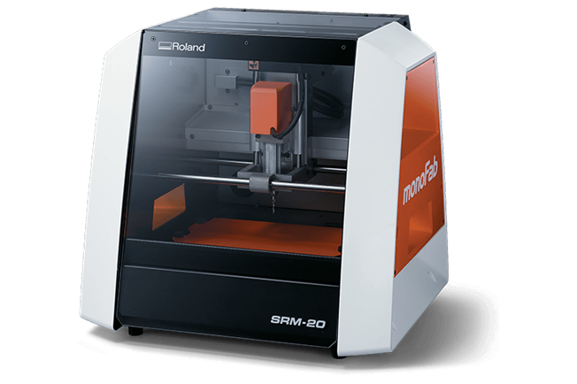
monoFab SRM-20
As a small milling machine, the SRM-20 offers compact size and powerful functionality
at an affordable price. Production of realistic parts and prototypes is made simple
and convenient with a device that fits into any office, home, or classroom environment.
Click to download the brochure
Download VPanel
The SRM-20 was designed with a number of technological advancements that include a touch-button VPanel controller to regulate feed rate, spindle speed and milling on a complete X, Y, Z axes. I downloaded the version for windows 10X64. NOTE: The controller only opens when the machine is connected

Design Considerations for Producing a PCB
On the group site you will find information about the operation of the slicer, safety rules and compatible materialsClick here to visit the group site
The mods power
How to prepare the cut

The process step by step
You can download files: Traces & Cut
 |
 |
 |
|
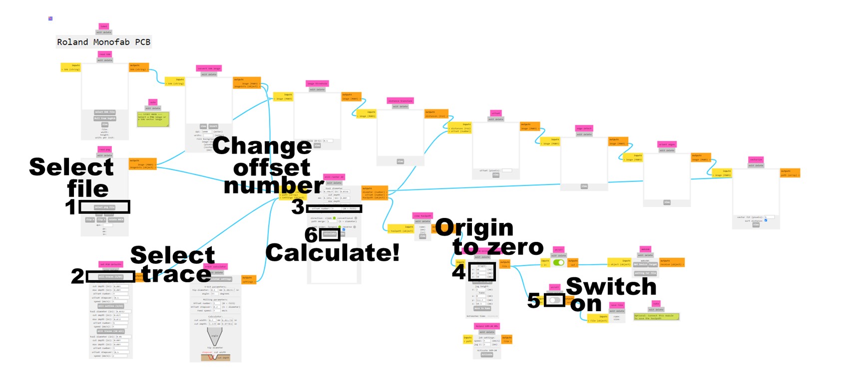
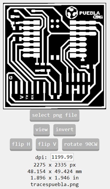
In Mods project, select the PNG with the first cut, which shows the design of the card. Additionally, I carried out the same process with the outline png, but I selected the "Invert" option so that the image colors would change and the program would recognize the correct cut. |
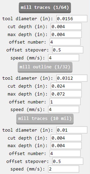
To engrave the card, select the "mill traces (1/64)" option, which already has a certain configuration. Now for the exterior cut option and select "mill Outline (1/32) |
I changed the "offset number" to 2 to record |
 |
 |
 |
| I changed all origin values to zero | And I activated the output to download the files automatically. These files will be the ones that we will enter into the machine controller. |
In the images we can see the route that our tool will follow to record the card. |
MONOFAB
This is how it cuts
1.-For the engraving process we use a sacrificial bed made of 3mm MDF to glue the copper plate.
2. We connect the machine to our computer with the drivers previously installed
3.-We select the tools that we will use for our engraving and cutting. In this case, we use a V-cutter and a small router.
4.- The controllers allow you to move the axes to make it more comfortable to change tools.
5.- We fix the sacrificial bed to the base with screws and an Allen key for greater security.
NOTE: If you use a sacrificial bed, you need to very carefully adhere the copper plate, making sure it is level, otherwise it could ruin your final cut.

Prepare files
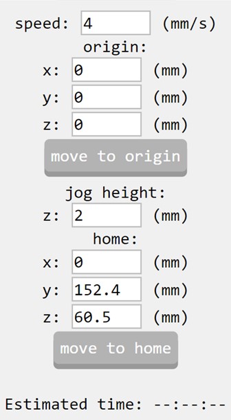
how to use VPanel
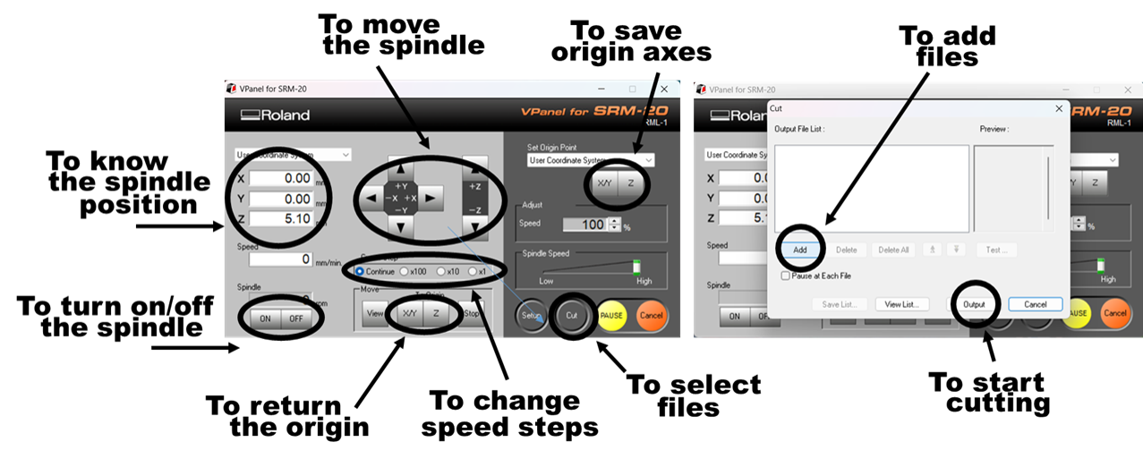
The controllers allow you to set your origin points on all three axes.
1.- we moved the spindle to an origin x and y where it is supposed to start our cut.
2.- With a sheet of paper we calibrated the distance between the spindle and the copper plate (z axis) making sure that the sheet was trapped and we saved the origin of Z
3.- To ensure that the spindle cuts the plate, we remove the sheet of paper and raise the spindle.
4.- We turn on the spindle and lower it until we reach 0 on our Z axis.
5.-Once the spindle touches the plate, we will lower the spindle (2 clicks x10) and verify that the spindle has left a mark on the plate, otherwise, we can give one more click.
6.- We load the engraving file and select Output to start engraving the plate
VERY IMPORTANT
7.-Change the engraving tool for the cutting tool and repeat the same process from step 5
8.-We load the cut file and select Output to start cutting the outside of the plate
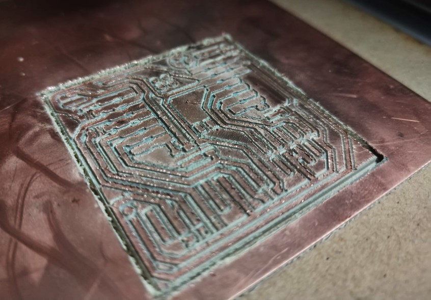
The milling process and results
To the first file
The engraving of the piece was not very precise, so I repeated the exercise with
a new cutter and when finished,
I cleaned it with compressed air to remove all residue.
Soldering
This is so hard!
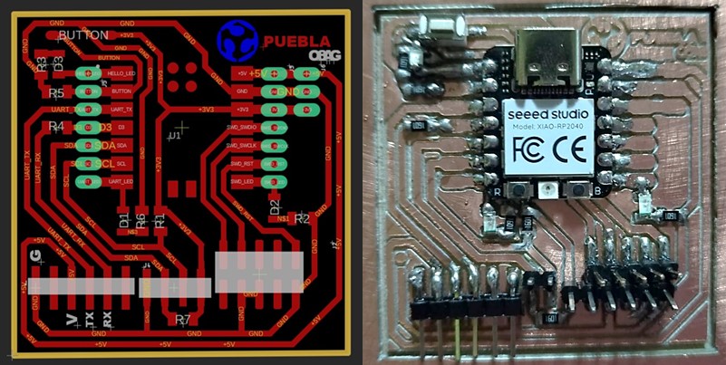
To solder the components, we took an image as a reference, which indicated the position of all the components.
COMPONENTS
- XIAO-RP2024
- LEDs
- Resistors
- PINs
- Button
The soldering did not turn out very well, but I did the first current tests with a multimeter and they worked well.
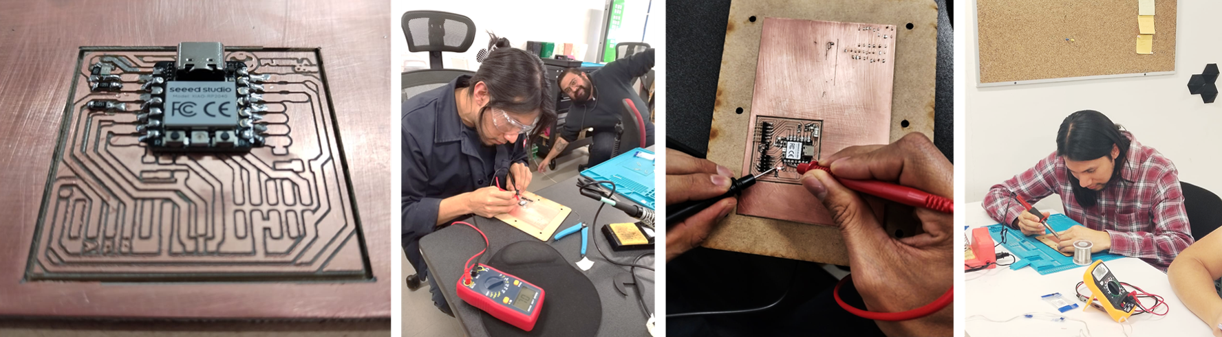
THE TEST
Check that you did a good job
To test that the welding of the parts is well done, you can connect the board with a
USB cable to a computer,
if the XIAO LEDs light up, it is fine, but if nothing lights up, disconnect immediately
Let's program!
That's supposed to be easy
 |
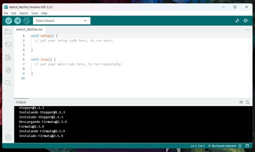 |
| The first step was to download Arduino. This is a free and open source software that you can easily. |
And once downloaded so that Arduino could run the program on my PCB, I had to indicate the name of the XIAO |
 |
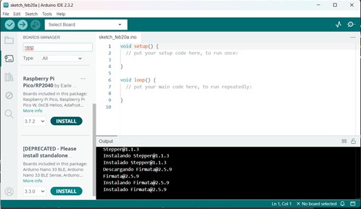 |
| I searched for the name of the XIAO and from a page I got the link corresponding to Arduino. In the same page is the step by step on how to do it. |
Then I downloaded the Board Manager corresponding to the XIAO. For these I searched for Raspberry Pi Pico/RP2024 and installed the 3.7.2 version. |
 |
 |
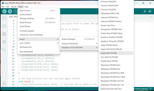
| We connect a type C cable to the laptop and look for it in the Arduino ports on the XIAO board. It must be connected to detect the port and the cable must output the communication signal. |
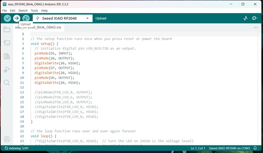
Then I opened the code that they had provided us from Arduino and we did a test to see if the LEDs turned on. |
It works!
This is the example code
Two LEDs should blink and the third LED only blinks when you press the buttonClick to download