9. Output devices
Week asignments
1. Group assignment: measure the power consumption of an output device
2.Individual assignment: add an output device to a microcontroller board you've designed, and program it to do something
Group asignment
Check out the Puebla FabLab repository: https://fabacademy.org/2024/labs/puebla/week9/
There are 3 ways of measuring the power of the system:
1. Gather the theoretical values of the components of the circuit, make a sum, and multiply it by a certain safety factor.
2. Use a multimeter if the element is passive/active/reactive, and it isn’t influenced by the frequency domain.
3. Use an oscilloscope if the frequence is used. The embedded tools help calculate all the square signal properties.
Individual asignment
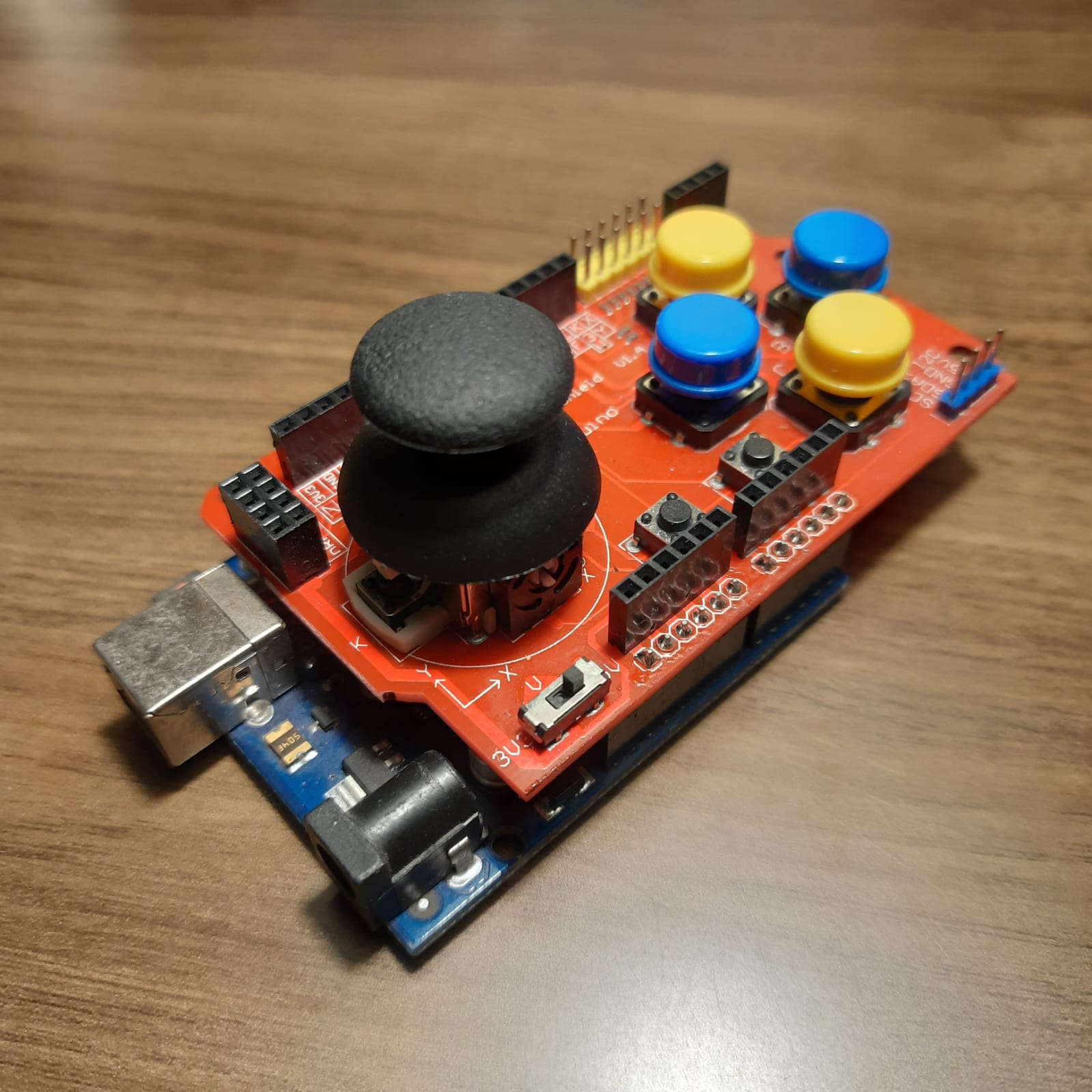
The board created for the final project already has an input (joystick) and an output (LEDs. Even when the LED array is simple, it represents the controll and mastery over digital outputs. The basic example if to make the LED array flash.
The board that I made consists of analog inputs (joystick) and digital outputs (Square array of LEDs). Originally, the design I wanted to create was some sort of unviversal control that includes analog inputs from the joystick, a camera sensor to identify my hand position and control the movement of the car, and finally, another type of analog sensors (ultrasonic) that transform a sound signal into a possible distance measurement. Of course, the lack of time narrowed it down to the simplest control there is: analog.

If you want to learn more about the design, manufacture, and coding of the component, I invite you to check my Fab Academy week #4. The output device are the LED’s and thew will serve as a graphical representation of the movement of the joystick/car.
Programming them was quite a complex task since I initially used a working benchmark (Arduino + Funduino) to test the logic of the program, and attributes needed. Turns out that the XIAO Seeed has ADC (analog digital converters) that work with 3.3 V instead of 5 V, and one of the most impressive things to do, was to investigate the directives because they are not the same for each board. Last minute changes were required, like soldering the VCC of the joystick in the 3.3 v terminal of the XIAO instead of the 5v terminal.
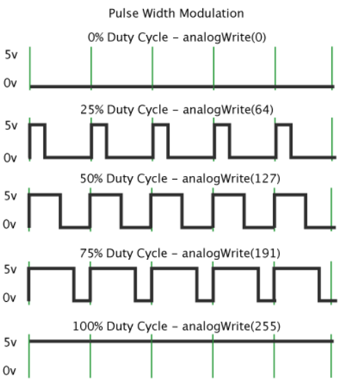
During the creation of this PCB I was able to play with the LEDs or outputs, two important concepts of digital manifestation: simple binary states (1,0), and every state in between: PWM. The theory dictates that logic value in electronics, is represented by 1 (top voltage, direct current) and 0 (ground). The PWM (pulse width modulation) values are generated by changing the amount of time that the digital state of an output is active in a short period of time. An image would explain it better.
The way the code is implemented into the Xiao is:
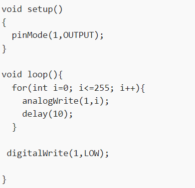
Finally, the flashing program let us compare that the signal needed for the inbuilt LED is the contrary to the digital outputs.