My Final Project
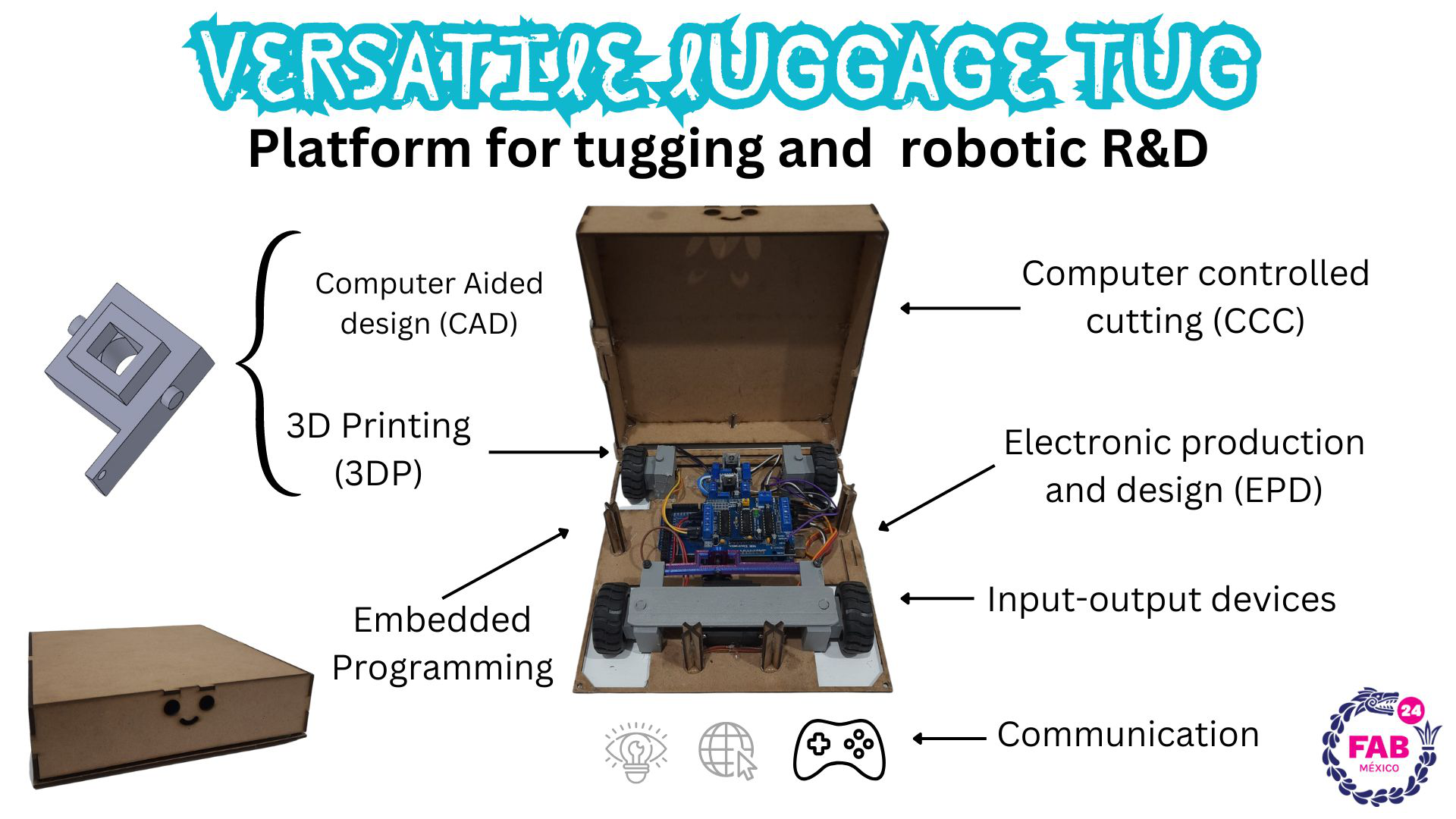
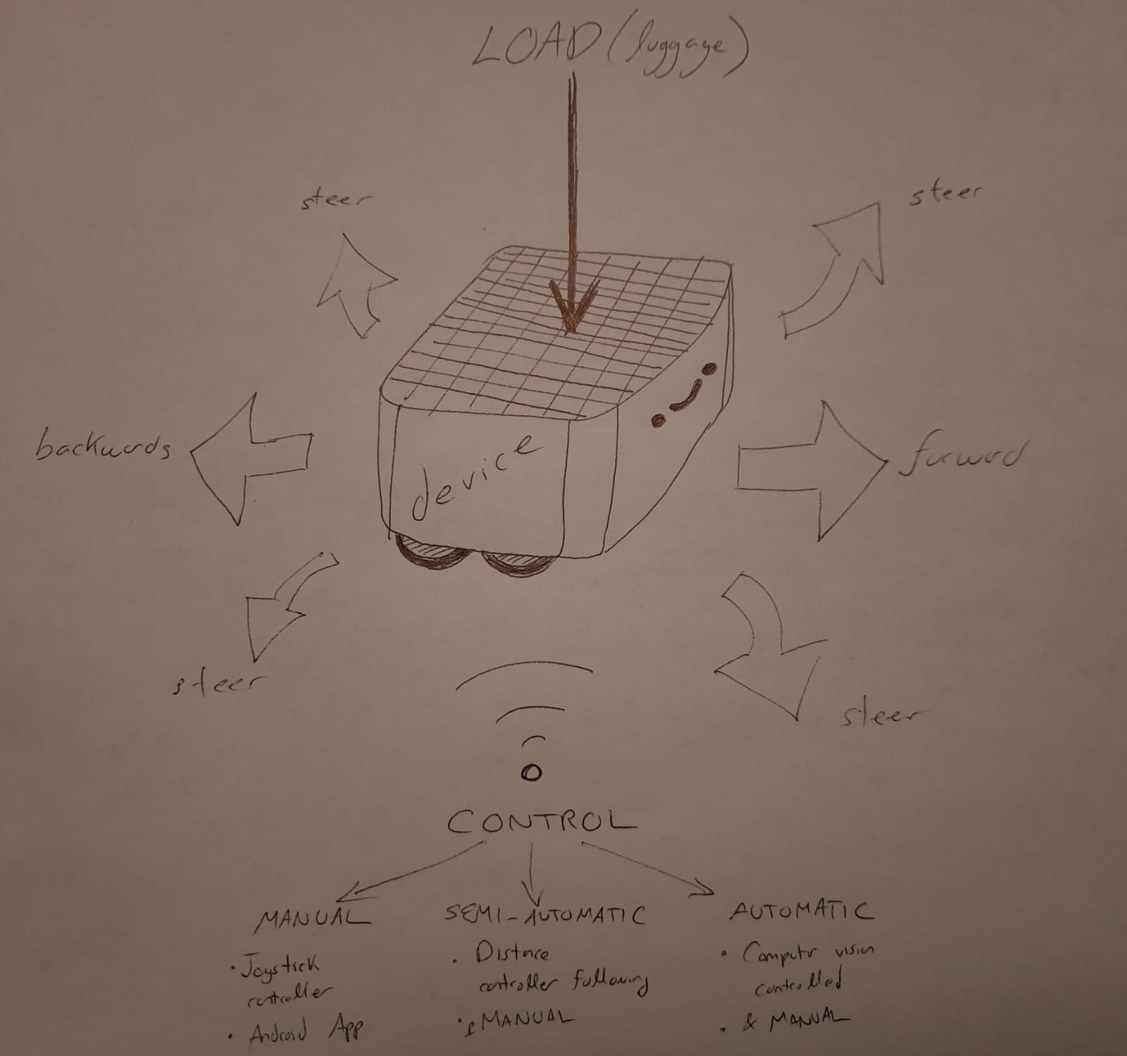
I have decided to make a car to help me transport my luggage through the airport. At the same time, I want to use this idea to test the different ways to control a vehicle: manually, semi-autonomous, and autonomous. It is hard to put a final name to it, so from now on it shall be referred to as "device".
On second toughts, the vehicle will be called "Smart Luggage Tug" and the achronym will be SLT. The manual controller will be referred to as "CTRL"
Results!
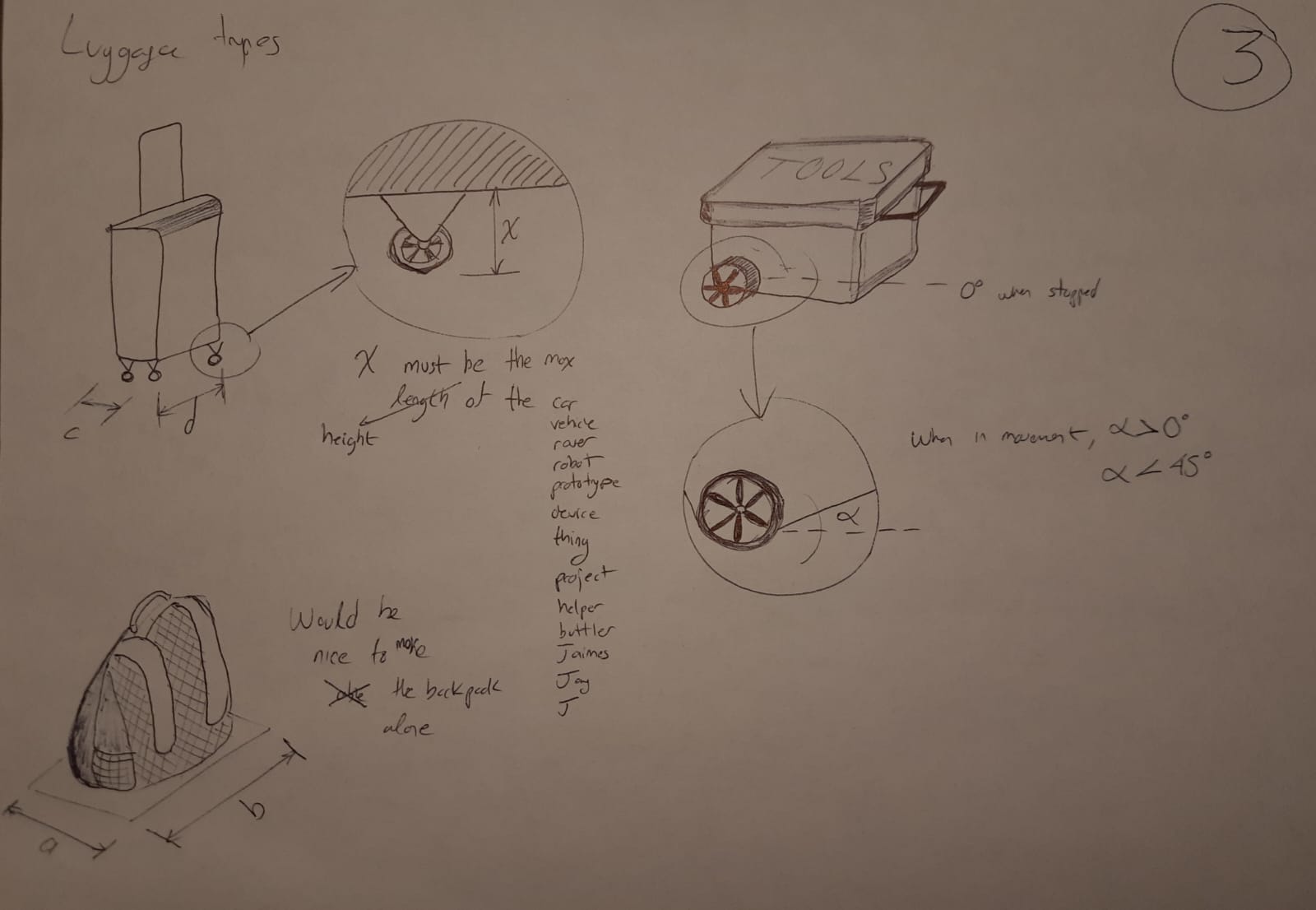
Sketching
Research
The problem solving method I used is composed by 8 stages:
Previous works
One of the most famous final projects in the Fab Academy program is the one from Omar AlDajani’s Strobot, which inspired the movement of objects without any manual intervention. https://fab.cba.mit.edu/classes/863.20/Architecture/people/OmarAlDajani/FinalProject/The%20Strobot.mp4 Another source of inspiration were the countless commercial models in the market that are already integrated in the carry-on luggage: https://www.travelandleisure.com/style/travel-accessories/smart-luggage Finally, all sorts of animals riding the robotic vacuum are a great example as well.
Materials
| Device | Material | Qty | Price (MXN) | Link |
|---|---|---|---|---|
| SLT | MDF 3 mm | 1 | 399 | https://www.amazon.com.mx/Tabla-manualidades-35x35cm-piezas-espesor/dp/B0BZMYQFD2/ref=sr_1_2?__mk_es_MX=%C3%85M%C3%85%C5%BD%C3%95%C3%91&crid=1U18C12WUZ17A&dib=eyJ2IjoiMSJ9.efLJLMj7 |
| SLT | Pololu Motorreductors | 4 | 400 | Local electronic store |
| SLT | Servo MG995 | 1 | 449 | https://www.amazon.com.mx/unidades-servomotor-velocidad-inteligente-helic%C3%B3ptero/dp/B07NQJ1VZ2/ref=sr_1_14?__mk_es_MX=%C3%85M%C3%85%C5%BD%C3%95%C3%91&crid=K8YUS6INZIT9 |
| SLT | Arduino Mega | 1 | 499 | https://www.amazon.com.mx/elegoo-2560-R3-ATmega2560-ATMEGA16U2-Cable-Compatible-Arduino/dp/B01H4ZLZLQ/ref=sr_1_2?__mk_es_MX=%C3%85M%C3%85%C5%BD%C3%95%C3%91 |
| SLT | Motor Shield | 1 | 135 | https://www.amazon.com.mx/HiLetgo-L293D-Protector-Compatible-Duemilanove/dp/B01DG61YRM/ref=sr_1_2?__mk_es_MX=%C3%85M%C3%85%C5%BD%C3%95%C3%91&crid=334LNPHV4QC9I&dib=eyJ2IjoiMSJ9.zkswl1P37Tst2- |
| SLT | HC-06 Bluetooth | 1 | 148 | https://www.amazon.com.mx/transceptor-Bluetooth-inal%C3%A1mbrico-Consumo-energ%C3%ADa/dp/B08G55FM18/ref=sr_1_2?__mk_es_MX=%C3%85M%C3%85%C5%BD%C3%95%C3%91&crid=2J96BO7THOTVB&dib=eyJ2IjoiMSJ9. |
| SLT | M3x10 screws/nuts | 3 | 371 | https://www.amazon.com.mx/tornillos-arandelas-m%C3%A9tricos-inoxidable-hexagonal/dp/B0C8TB9FDM/ref=sr_1_1?crid=1JM9KN21YLR17&dib=eyJ2IjoiMSJ9.zW2LYdus7R6QFCuJhw-670xXfxR24dh2vJaJxkbiGGaQ0aKJYuDdA6txbvSEW_TdBAG6zzmrJzS3bBhJey8aFIedGjjiaBnuQ8Jq1AtkeA_Er6R39CDIb- |
| SLT | Hot glue | 1 | 29 | https://www.amazon.com.mx/Truper-REP-PIPE-5-16-Barras-Silic%C3%B3n/dp/B00V8J6RJK/ref=sr_1_1?__mk_es_MX=%C3%85M%C3%85%C5%BD%C3%95%C3%91&crid= |
| SLT | Voltage Regulator | 2 | 60 | Local electronic store |
| SLT | DeWalt 12VCD 2Ah battery | 1 | 1200 | Local hardware store |
| CTRL | Copper clad laminate CCL | 1 | 261 | https://www.amazon.com.mx/circuito-laminada-revestida-Aoje-Link-5piezas/dp/B091SRQ912/ref=sr_1_1?crid=AZ9HXQPL2N7Y&dib=eyJ2IjoiMSJ9.3v70tokJ8Ego898nIxZK81Gi9V__gm3r96npKWkv2s3f1TOda7mtCm_dohh4lExQX0xetAANMAbIVejiIzU6AHy6TlmAY__4QsjDDlBGJJ-sZ8TbnMzMFLu4kXE-3d1zpqnneQM-3AsCcFq0_F8tvczoMFRnBtNt9Fa0B1gSELFd5RgX2pd9JQ7rKIdl7kD8t0hR1x293PSGpq9hpROCKEKnAi9BB32tdQaIhWQGTGNMCJF774O2ErpZQ4GcgANVQZBO0_MbSvTsHQ7SPazWeBAs8YADAJMVSf_zviLhChU.Q_YtKM4ZQ072HmQsqTNrrHdZ3sj3Dd1zlgChrbFIoqI&dib_tag=se&keywords=placa+fenolica&qid=1719299199&sprefix=placa+feno%2Caps%2C169&sr=8-1&ufe=app_do%3Aamzn1.fos.242f5c11-6cfd-40d6-91f6-be3d1974080c |
| CTRL | Analog Joystick | 1 | 106 | https://www.amazon.com.mx/Joystick-Gamepad-Controller-Palanca-Control/dp/B07WF8LVBQ/ref=sr_1_6?crid=1VOOKSUUFV1J5&dib=eyJ2IjoiMSJ9.AQLzTlDBxdjokpEQ5VZXa0hpFc67XP4pr-WYNiXpzKFUdAsq4o9X51 |
| CTRL | Dupont Jumpers | 1 pack | 140 | https://www.amazon.com.mx/MV-Cables-Jumpers-Multicolor-Protoboard/dp/B094YTXD4K/ref=sr_1_1?__mk_es_MX=%C3%85M%C3%85%C5%BD%C3%95%C3%91&crid=2U1NEXZFCTFRB&dib=eyJ2IjoiMSJ9.96wLDLd3Onhkf4Sx9Vec- |
| CTRL | Surface mount SMT LED | 4 | 40 | Local electronic store |
| CTRL | SMT 330 Ohm resistors | 4 | 40 | Local electronic store |
| CTRL | XIAO Seeed ESP32C3 | 1 | 362 | https://www.amazon.com.mx/Seeed-Studio-XIAO-ESP32C3-Microcontrolador/dp/B0B94JZ2YF/ref=sr_1_2?__mk_es_MX=%C3%85M%C3%85%C5%BD%C3%95%C3%91&crid=33WYA8899TF28&dib=eyJ2IjoiMSJ9.- |
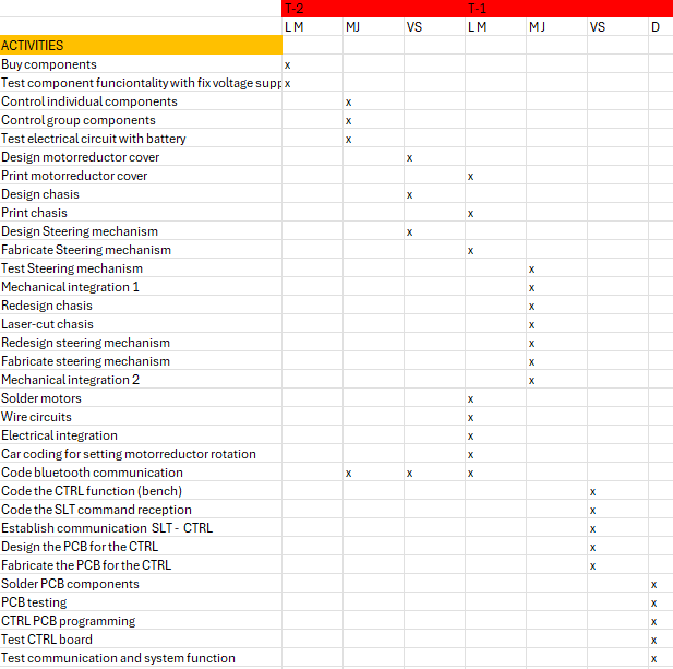
SCHEDULE
The following table shows the last two weeks before the final presentation:
SMART LUGGAGE TUG (SLT)
Mechanical design
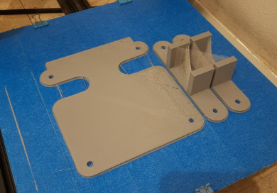
The following components were design based on the size restrictions of the standard luggage height, and the size of the electrical components.
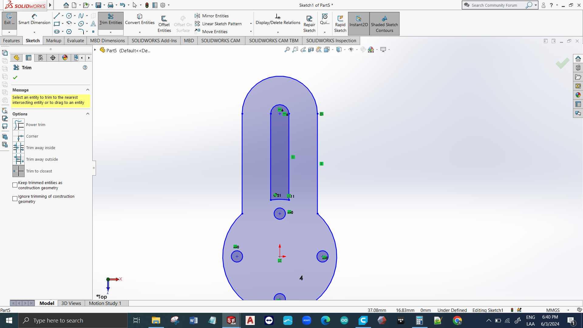
MOTOR BASE
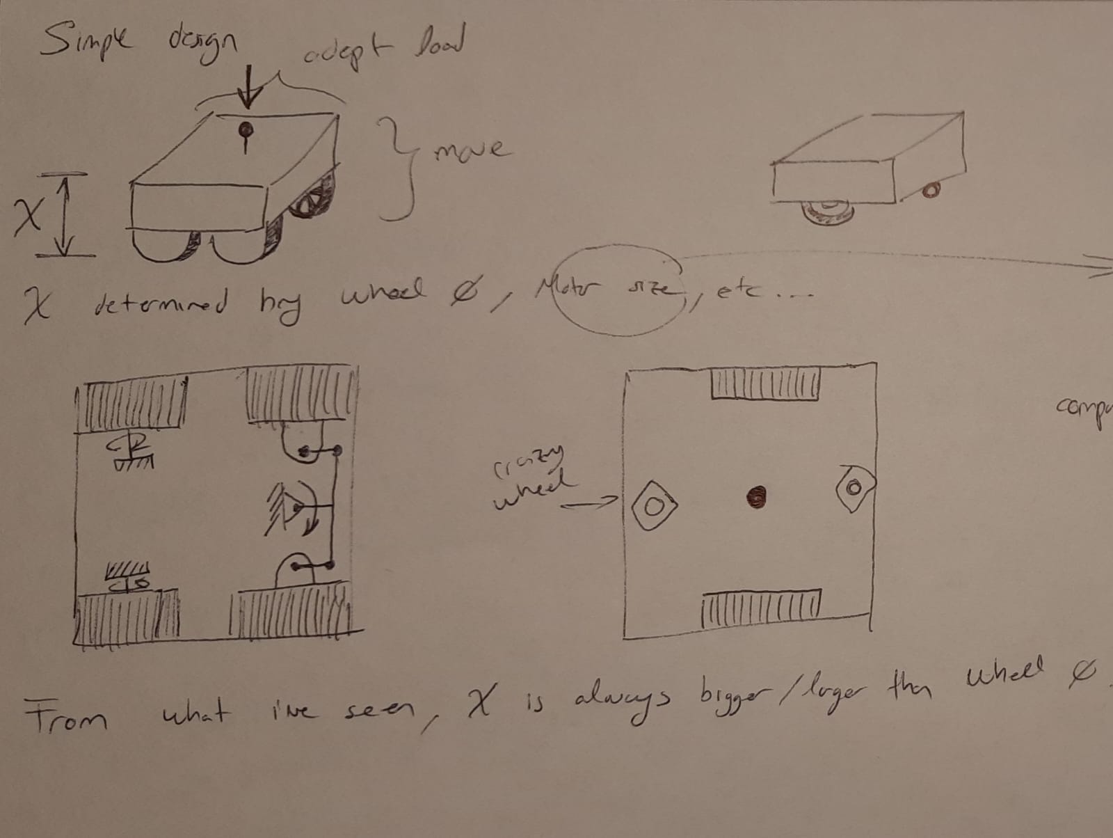
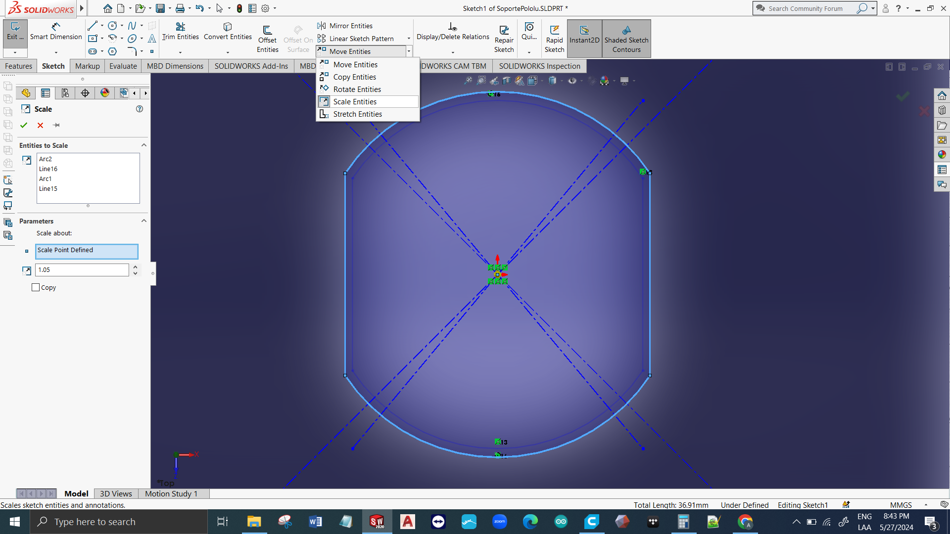
First thing to do is measure the component and sketch possible solutions while maintaining the design under 55 mm in height. After sketching a satisfactory solution, we should model the piece using SolidWorks.

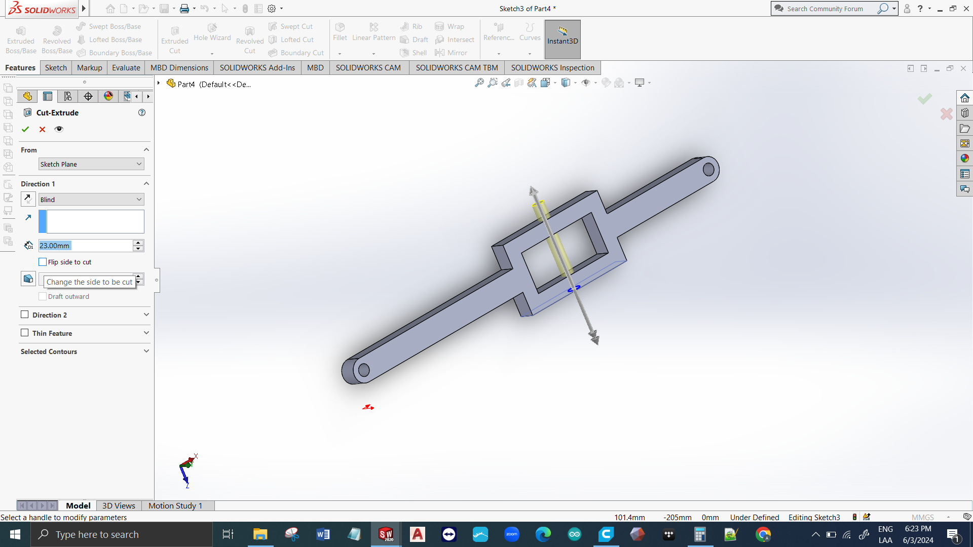
STEERING MECHANISM
The idea came out of some RC cars that were in my collection. The principle for these mechanisms is a 4 bar linkage mechanism (now I understand why most of the car/robotic platforms in the market don’t use this). To the previous design we should add the bar connecting both front wheels and we should design the actuator that moves said bar using a servo.

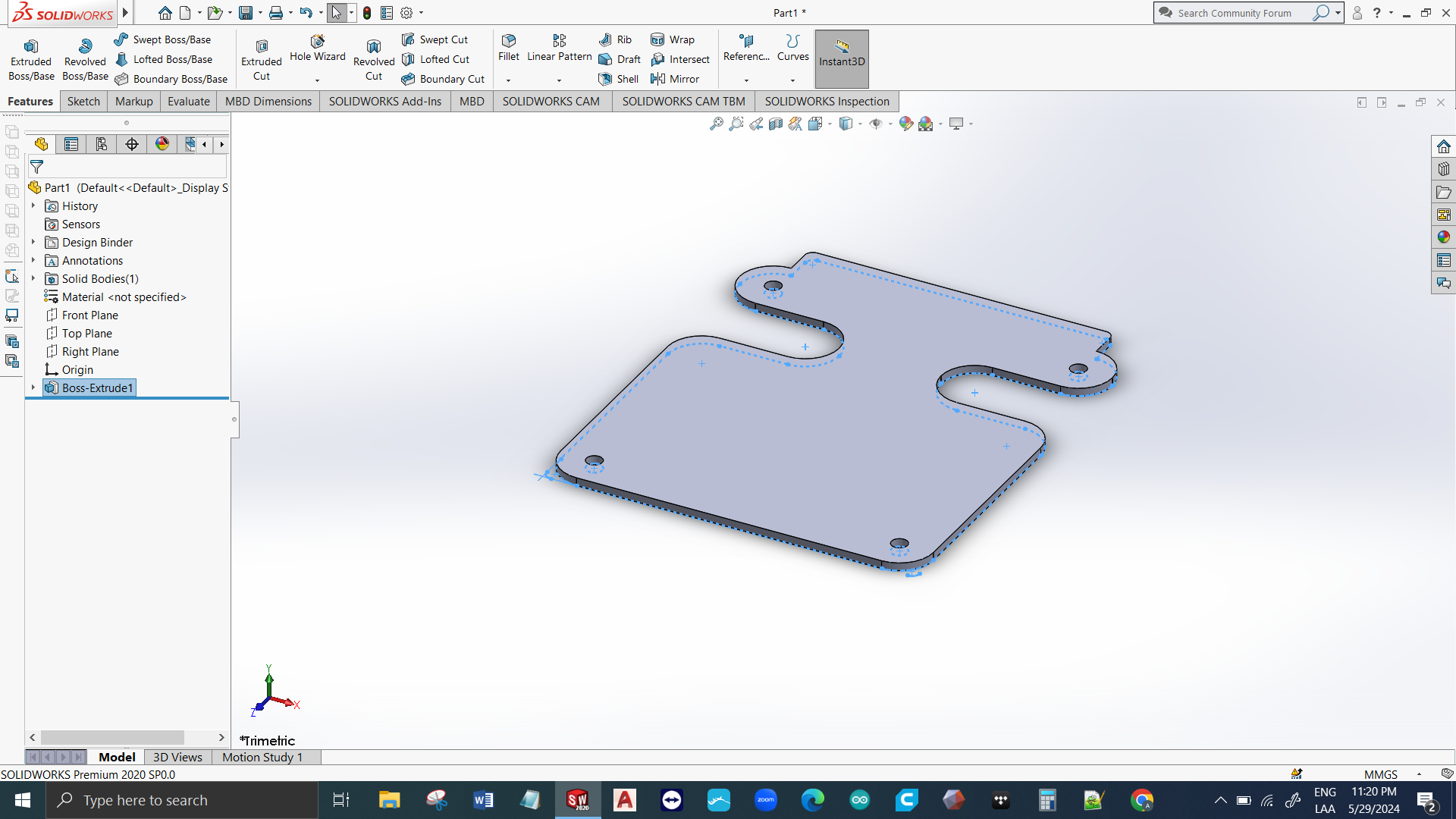
CHASIS
To fit the previous components, we should consider the standard area below the carry-on luggage which is 180 x 180 mm2. The displacement of the steering mechanism should be considered, and a minimum layout size for the electronics (100 x 60 mm2 for the Arduino Mega) The first iteration was designed to be 3D printed, the second version was designed to be laser-cut.
Manufacture
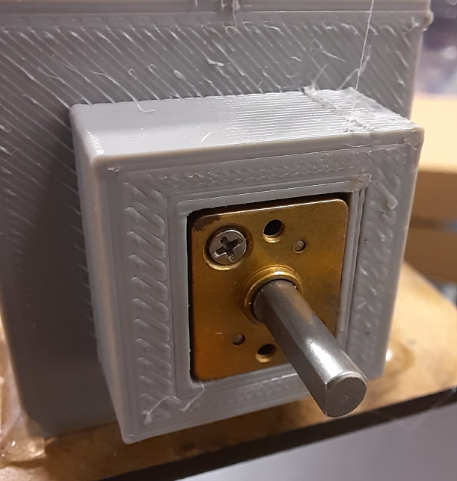
MOTOR BASE
1 iteration needed. This component took to most amount of time to be designed. I was trying to reach perfection in the first cycle, but that took a lot of time and I don’t recommend it. Try using the following advice: KISS (Keep It Simple Stupid) and “Better done than perfect”. BTW, playing with the tolerances for the components is quite risky: too little tolerance and you will have to pound the component to fit. Too much tolerance and you will have to compensate for the missing materials with prisoner screws or glue.
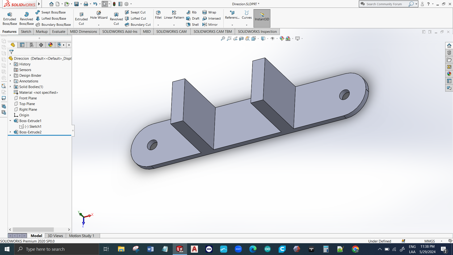
STEERING MECHANISM
3 iterations needed. First iteration for the linkage was to small. Second iteration for the linkage was to brittle due to the lack of filling in the 3D printing piece. The third iteration was for making a smaller servo adapter.
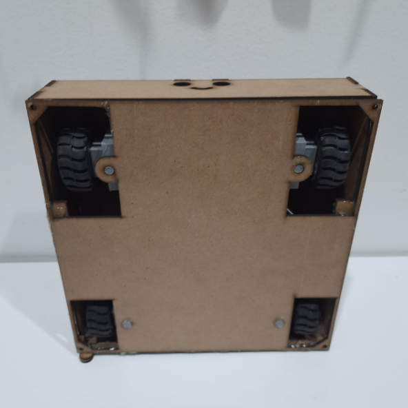
CHASIS
3 iterations needed. First iteration was 3D printed and weather conditions made it convex under the so called “warping” effect. The second iteration had almost no space for the electronics, and it was too narrow in the body/steering connection. The third iteration had the perfect space for electronics and enhanced structural strength.
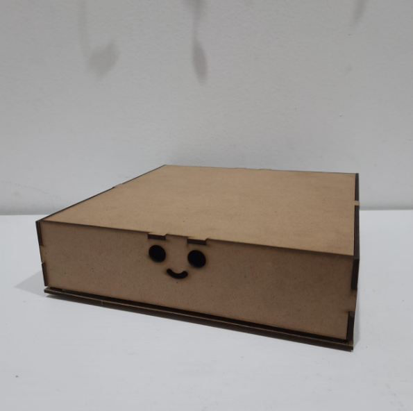
CASING
2 iterations needed. First iteration didn’t contemplate the kerf, and it had calculation issues that were not considered in the sketch. Second iteration considered the kerf, a perfect box shape, and supports were created to improve the load distribution and avoid flexing.
Electrical design
MOTORS
The Pololu micromotorreductors 1000:1 were selected due to the torque that they provide. A steady operation current is around X Amps per motor, Y Amps in total. Which should be perfectly handled by the Motor shield.
SERVO
This servo has a stall current of X Amps and should have its own voltage regulator.
CONTROL
An Arduino Mega has 4 serial ports that can be used simultaneously. Since the intention of this project is to be used as a robotic R&D platform for adding multiple peripherals, its better to have a lot of digital and analog ports that don’t interfere with the Motor shield layout.
COMMUNICATION
Taking advantage of its multiple serial ports, and the need for wireless communication, a Bluetooth module was selected to establish connection with the remote control that will be using the same technology. A challenge for communication is establishing automatic connection between 2 modules the moment they are powered without manual intervention. This is done by configuring them with AT commands (HC-05, HC-06)
POWER
The total amount of current consumed by the device is X amps, it should come from the same power supply but there should be 2 branches: 1 for the components that use 5 VCD, and the second for the 7 VCD for the servo. Since I already have DeWalt tool batteries 12VCD, 2Ah, an adaptation was implemented to supply voltage to both branches. The voltage regulation was made through the Z module.
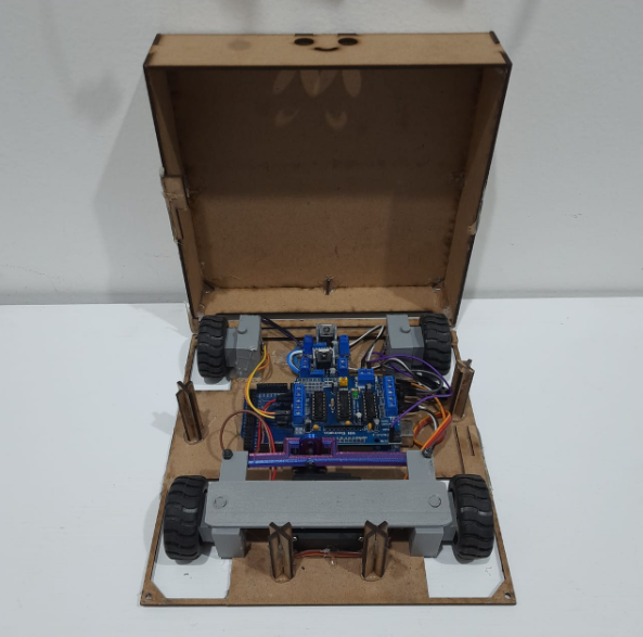
Electrical integration
LAYOUT
All the components were wired and positioned using hot glue, the motors were soldered, and the wire management went quite well due to the usage of the shield, and proper Dupont jumpers length selection.
PROGRAMMING
Using the shield libraries, a program was developed to go forward for 3 seconds, stop for 2 seconds, and go backwards for 2 seconds. This helped to verify the overall performance and to adjust the rotation direction of the motors. Obviously, all motors should work with the same direction at the same time.
TESTS
After adjusting the direction of the motors, the carry-on luggage was placed in front of the SLT and it moved!
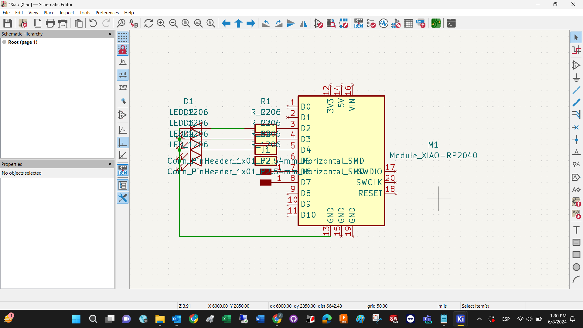
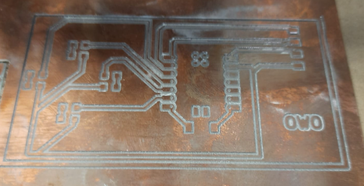
REMOTE CONTROL (CTRL)
Electronic design
Of course, KiCad was used for the PCB design. This is a rather simple device that reflects the position of the joystick using LEDs at the same time it indicates the SLT on which movement should be done.
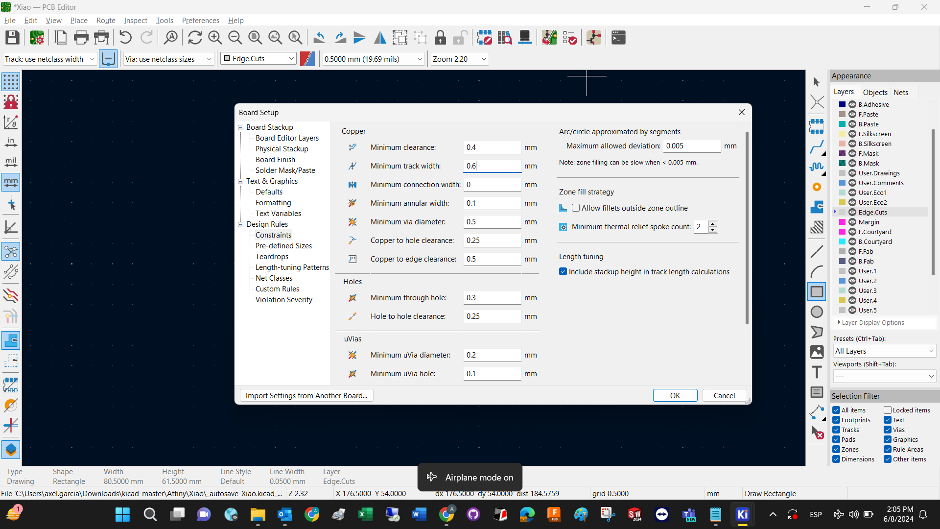
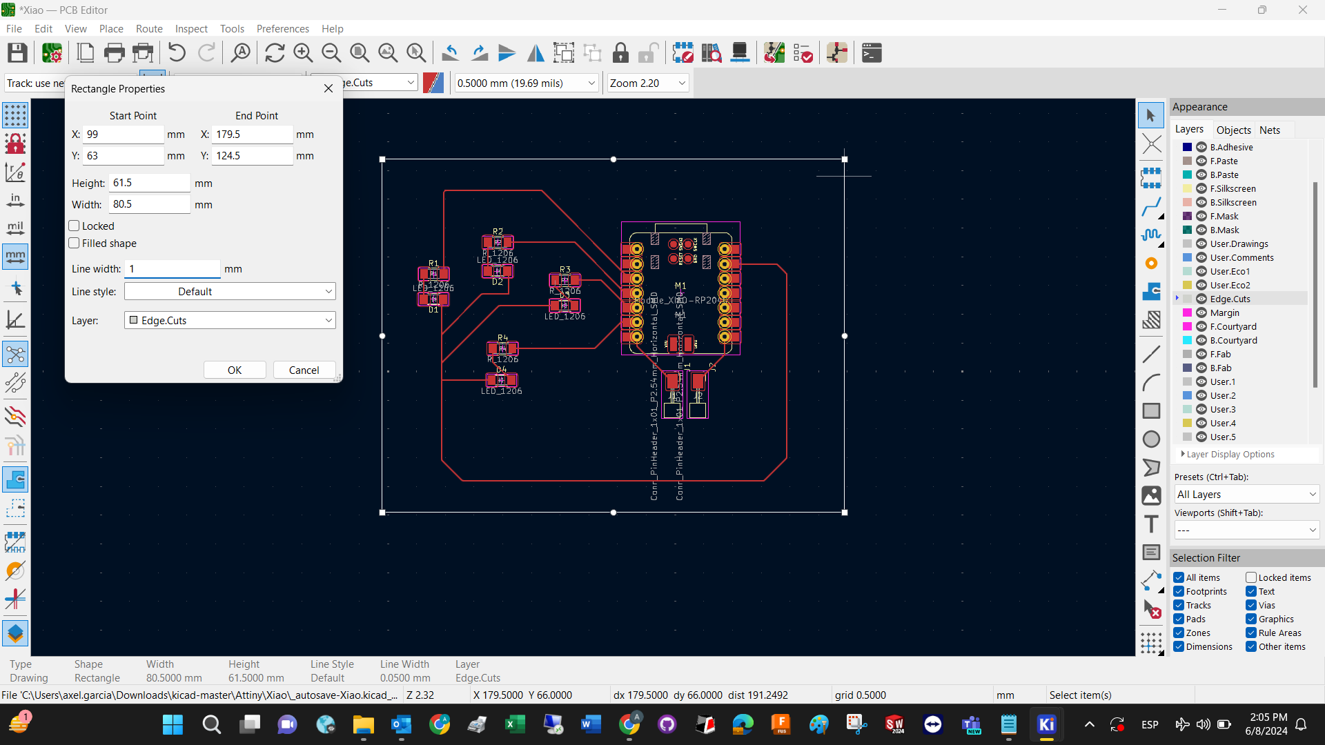
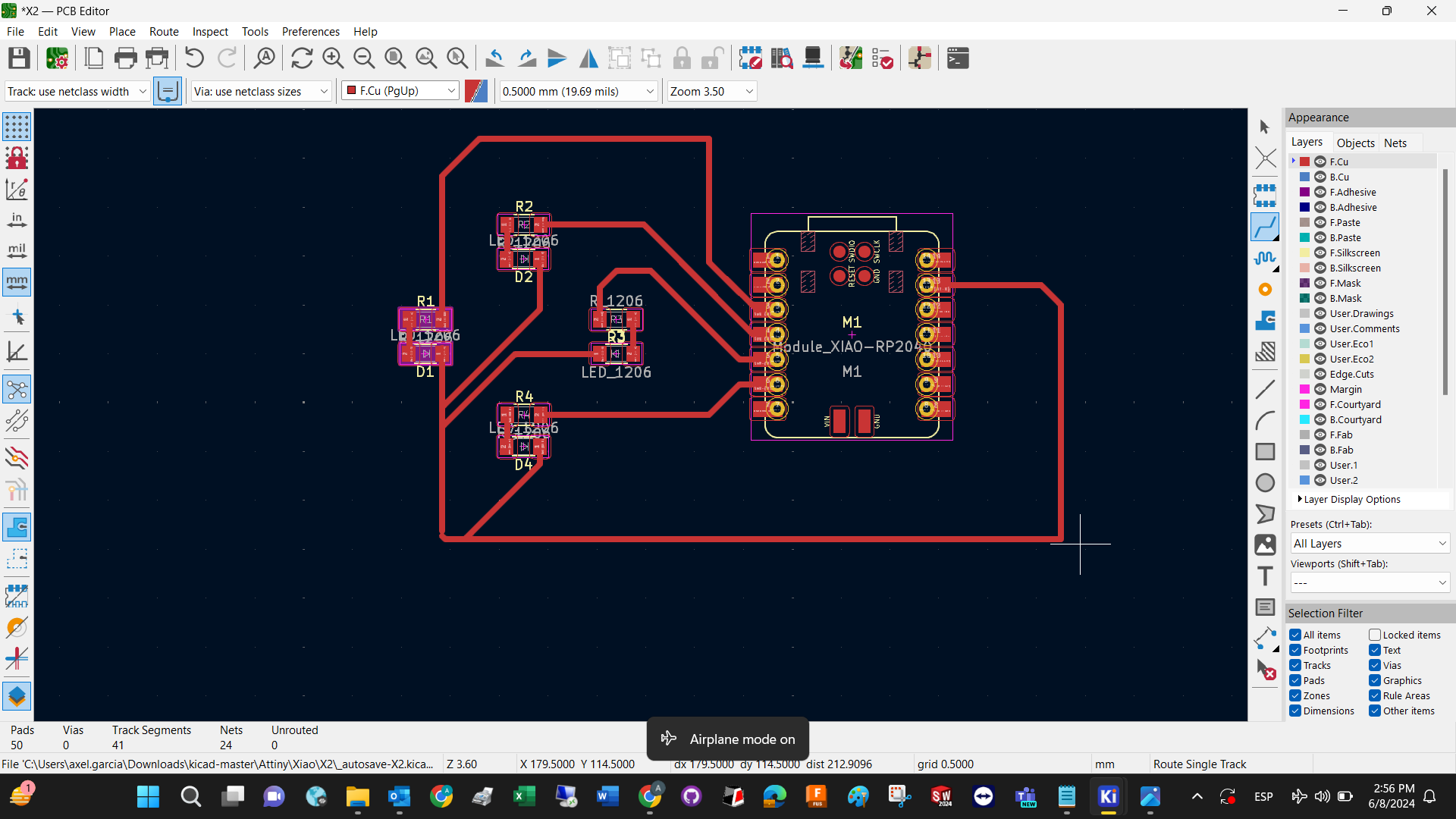
Electronic manufacture
VPanel and its respective machine was used for the creation of the PCB. No issues were found during the manufacture. The soldering improved considerably from the first practice, but sanding the copper plate was necessary to enhance the adhesion.
Before solderng the XIAO, the back of the component had to be isolated to avoid shortcuts, and a blinking program was uploaded to verify every port and component works.
Programming
A program to turn a specific LED according to the position of the joystick. This was the code that was used for displaying the position of the Joystick and sending a command to be interpreted by the SLT.
INSERT CODE PLS uwu
INTEGRATION
On the video below you can observe the cmmunication/actuation between CTRL and SLT.
Little bit off-topic, but check out the view after staying up all night to deliver the final project on time. Thanks for the memories!