13. Embedded Networking and Communications
On this week I learned to communicate different microcontrollers using some protocols.GROUP PAGE .
Communications
Communication protocols are a set of rules and standards that allow electronic devices to exchange data with each other. These protocols determine how data is sent, received, and verified, ensuring that devices can communicate efficiently and accurately. Some of the most commonly used communication protocols are the following:
I2C
I2C (Inter-Integrated Circuit) is a synchronous serial communication protocol that uses two lines (SDA and SCL) to connect multiple devices. It allows for multiple masters and slaves on the same bus, with 7 or 10-bit addresses. Typical speeds range from 100 kHz to 3.4 MHz. It is used in sensors, RTCs, and EEPROMs.
- SDA (Serial Data Line): Serial data line used for bidirectional data transmission between devices.
- SCL (Serial Clock Line): Serial clock line used to synchronize data transfer between devices.
SPI
SPI (Serial Peripheral Interface) is a synchronous protocol that uses four lines (MOSI, MISO, SCK, SS/CS) for high-speed full-duplex communication between a master and multiple slaves. The communication speed can reach several MHz. It is commonly used in flash memory, sensors, and LCD displays.
- MOSI (Master Out Slave In): Data line used to send data from the master to the slave.
- MISO (Master In Slave Out): Data line used to receive data from the slave to the master.
- SCK (Serial Clock): Clock line used to synchronize data transfer. It is generated by the master.
- SS/CS (Slave Select/Chip Select): Line used to select the slave device with which the master wants to communicate. It is activated by the master.
UART
UART is a serial communication for asynchronous data between TWO Devices using a transmiter (Tx) and a receiver (Rx). For the communication it sends one bit at a time in a single data line with the use of start/stop bits for the data frame. It is used for point to point communication between devices in short distances and connecting peripherals (GPS, Bt, sensors).
- TX (Transmit): Transmission line used to send data from a device.
- RX (Receive): Reception line used to receive data to a device.
for this project (I2C protocol)
For this project, I will use the I2C communication protocol (SDA and SCL), as it is the most practical and easy to use for this practice. I will create a system of boards that are easy to connect with each other, with an analog output. Each board will have the capability to connect only one device (button, LED, servo, potentiometer, etc.) to create different modules depending on what I want to add.
materials
Master
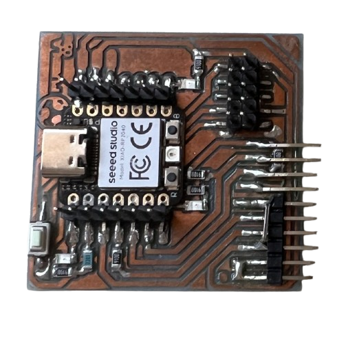
- Board Quentorres
Modification: connect the 5v pin to the 6th pin, this pin that is not connected to anything.
Slaves
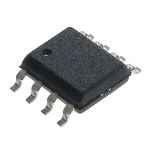
- Attiny412
- Led smd
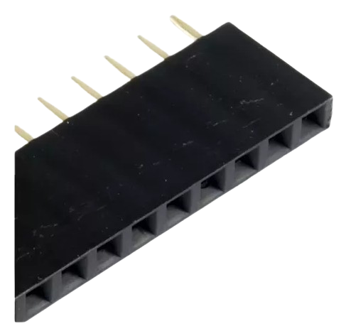
- male pins
- female pines
designed
Slaves
For the design of the slave board, I will use the KiCad program and the FAP Academy library. The idea of the board is to create a small, very simple board with quick connection pins. PCB SLAVE
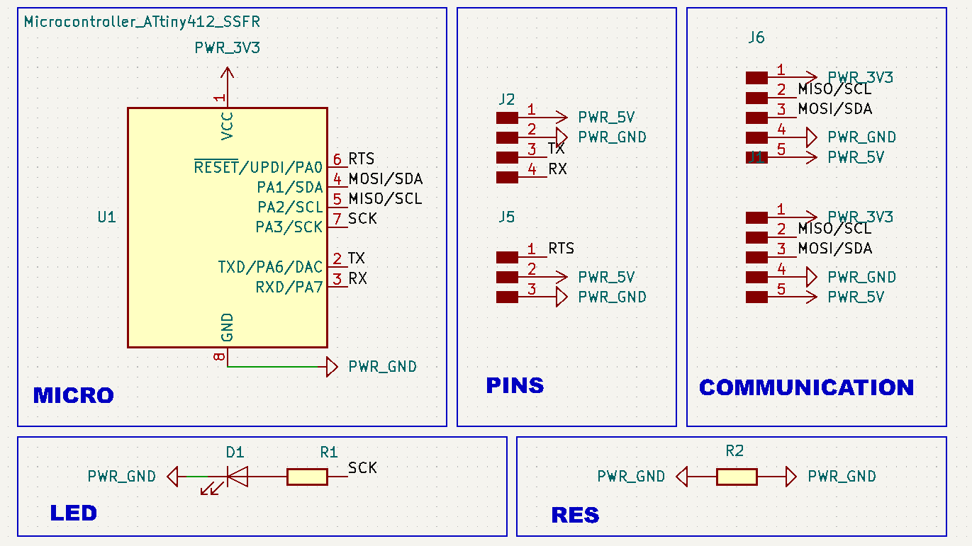
schematic
For the microcontroller, I will use an ATtiny 412, as I don't require many pins. I have I2C communication pins for input and output to connect multiple boards via I2C, as well as output pins to connect external devices, and an LED to verify if the board is functioning.
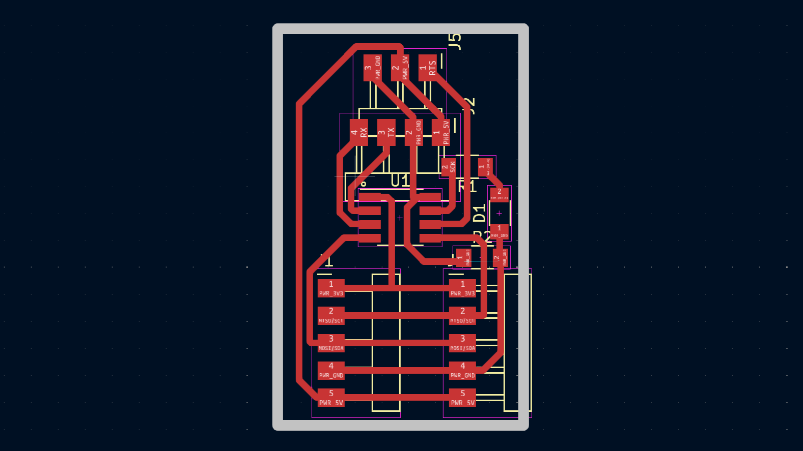
board
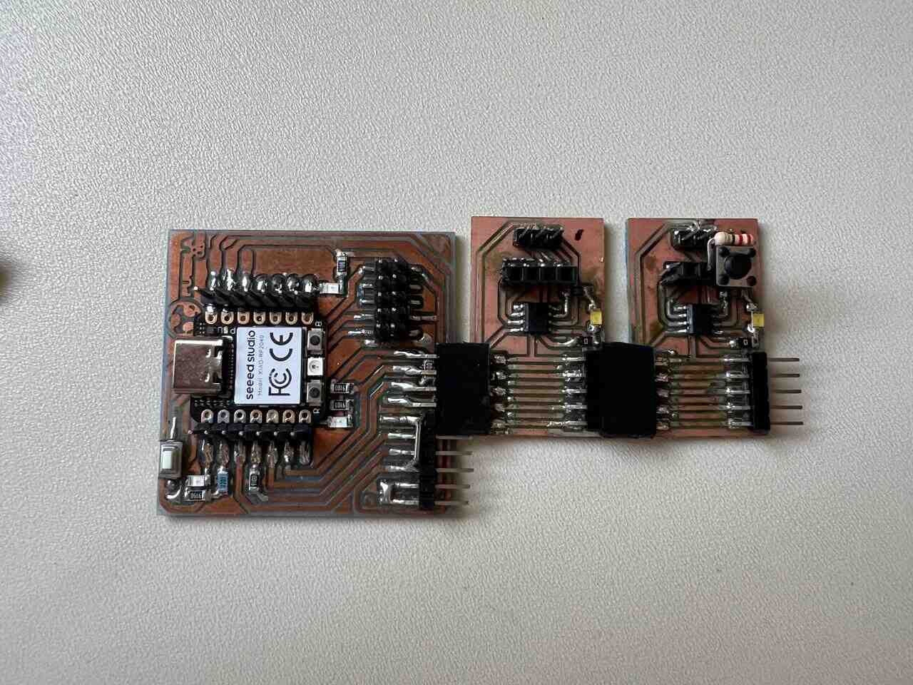
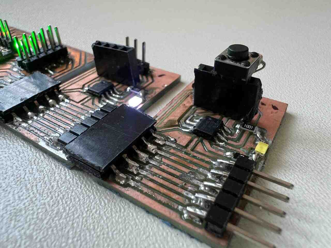
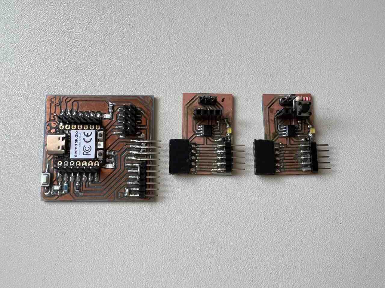
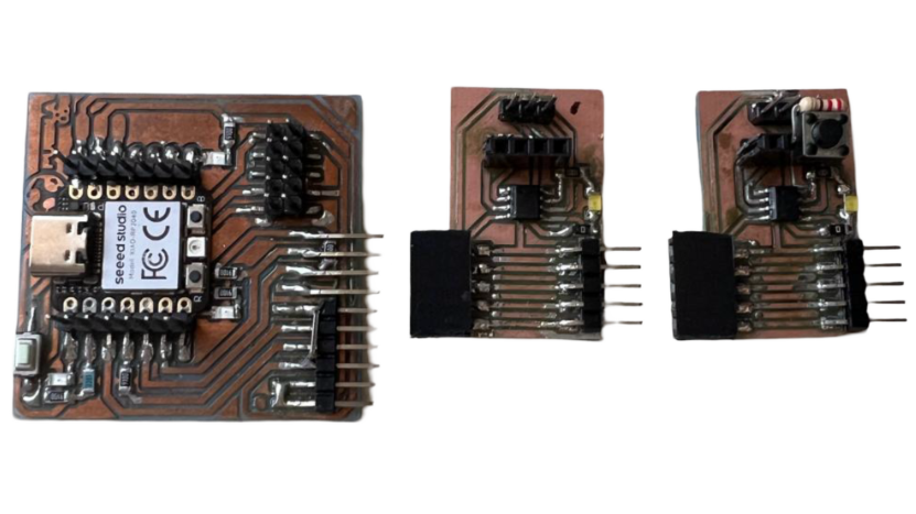
For the physical design of the board, I prioritized the communication pins to facilitate the connection between boards. The communication pins are located at the bottom. The microcontroller and LED are in the center. At the top, there are the power supply pins, programming pins, and output pins for external devices.
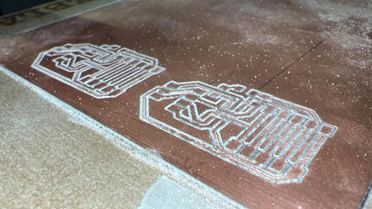
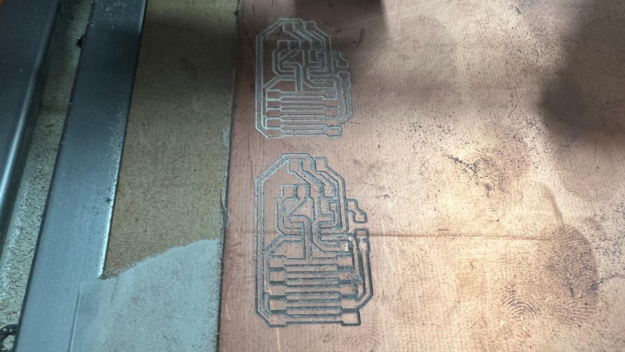
manufacturing
For the manufacturing of the board, you can review the manufacturing process from WEEK 4 and WEEK 8 . Here, you can see some images of the process, as well as how the components were soldered. SVG
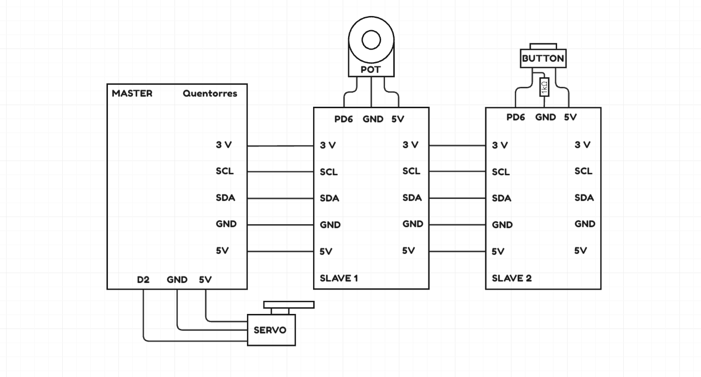
connection diagram
Here you can see a connection diagram of how the boards will be connected to each other. I used the I2C communication protocol for communication between the boards. The master board will have a servo connected to it. Slave 1 will have a potentiometer, and Slave 2 will have a button.
programming
To program the slaves in the ATINY412, I used an Arduino NANO and programmed it to be used as a
UPDI programmer.
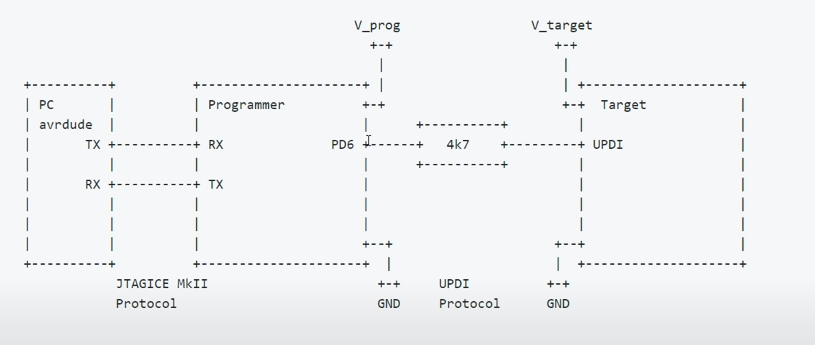
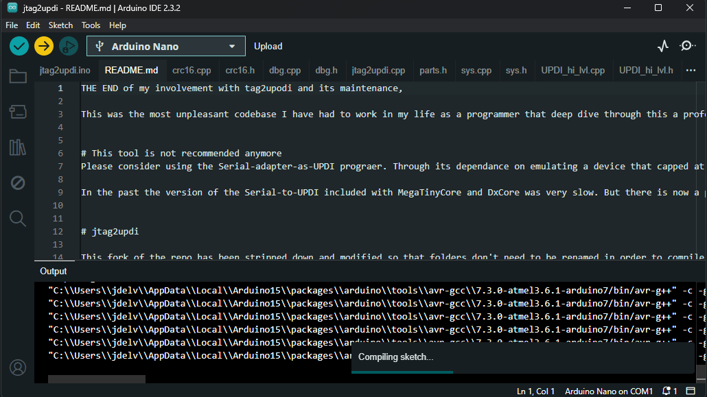
To convert an Arduino Nano into a UPDI programmer, I used
SpenceKonde's "jtag2updi"
code, which can be found online, and the megaTinyCore library. For more
information, check out the
following VIDEO .
(https://drazzy.com/package_drazzy.com_index.json)
updi programmer
- Arduino nano
- Protoboard
- Capacitor 10uf
- Resistance 4K7
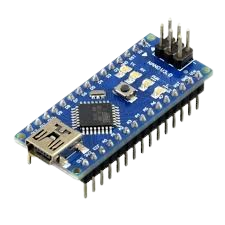
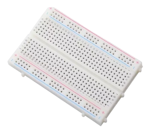
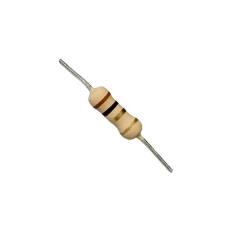
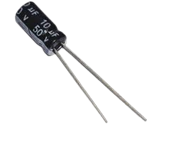
We will place the Arduino Nano on the breadboard and add a 10uf capacitor between the GND and RESET pins to stabilize the RESET signal. We will add a 4.7K resistor to the PD6 pin of the Arduino Nano, and this will be our output signal for the UPDI programmer.I used a potentiometer, as it is a variable resistor, and adjusted it to the correct resistance using a multimeter.
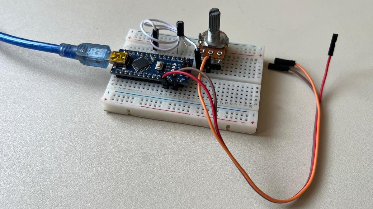
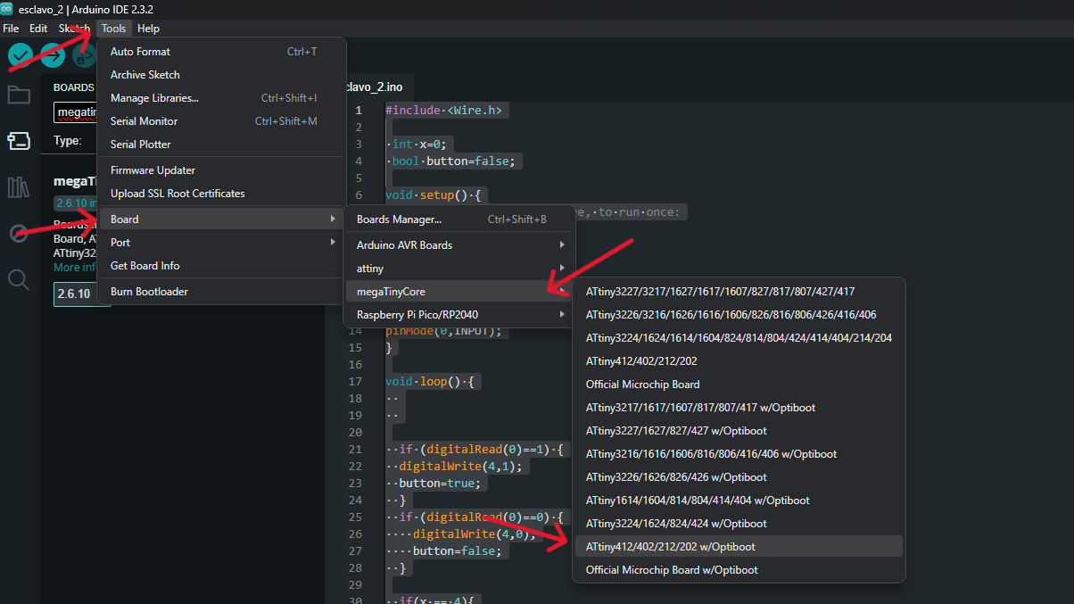
We will download the aforementioned program as a zip file. After extracting it, we will save everything in a folder with the same name as the program and upload it to the Arduino. Within Arduino, with the megaTinyCore library installed, we will search for the ATtiny 412 microcontroller to start uploading code to our slave boards.
code
Before explaining my code, I will provide a brief explanation of how the main library for I2C communication, which I will be using for this practice, works.
wire library
The Wire library in Arduino is essential for facilitating communication between devices using the I2C (Inter-Integrated Circuit) protocol. This protocol is widely used to enable communication between a microcontroller and multiple peripherals through a serial data bus.
| Función | Descripción |
|---|---|
| Wire.begin() | Initializes the library and, by default, sets the Arduino as a master in I2C communication. If you want to set it as a slave, pass the slave address as a parameter. |
| Wire.requestFrom(address, quantity) | Requests data from a slave device with the specified address. The quantity of data to request is specified in the second parameter. |
| Wire.beginTransmission(address) | Begins a transmission to a slave device with the specified address. This prepares the Arduino to send data to the slave. |
| Wire.write(data) | Sends data to the slave device. This method can send a single byte or a string of bytes. |
| Wire.endTransmission() | Ends the transmission and sends the data to the slave. It can include an optional parameter to send a stop or repeated start condition. |
| Wire.available() | Returns the number of bytes available to read from the slave device. |
| Wire.read() | Reads a byte of data received from the slave. |
My CODE
Below, you can see each of my codes loaded onto the master, slave 1, and slave 2. Each one is
different and performs an action according to what is desired.
The master performs two
functions. It changes the state of the RGB LED depending on the signal sent by slave 2 and modifies
the position of the servo depending on the signal sent by slave 1. Slave 1 has a potentiometer added
to control the servo connected to the master, and slave 2 has a button that operates a counter to
select the possible states of the master's LED color. CODES
Master
Slaves 1
Slaves 2
final result