MY FINAL PROJECT
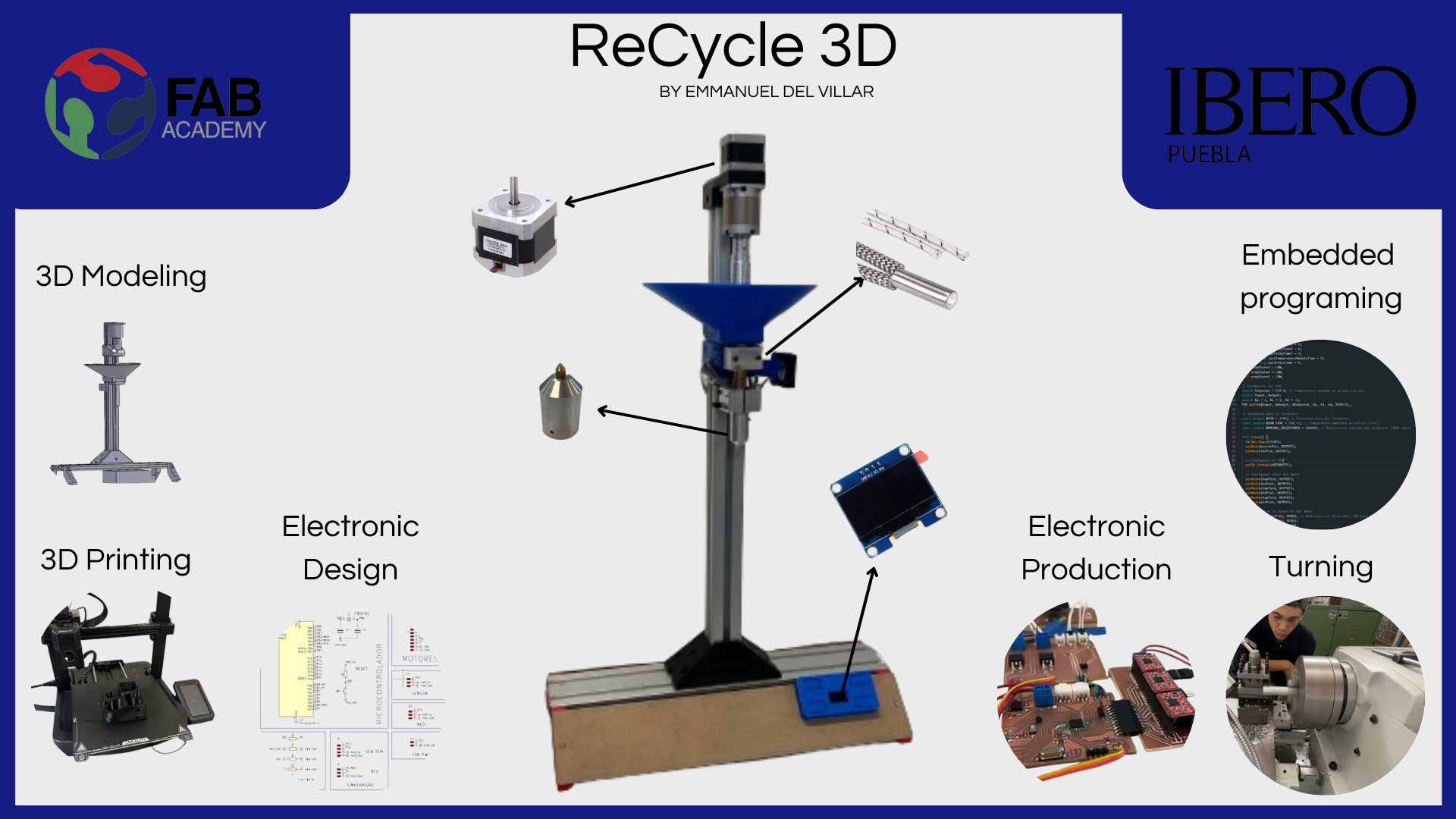
poster
video
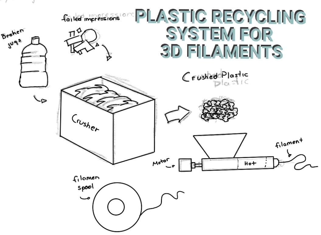
idea for this project
The idea for this project is to create a complete recycling system for 3D prints for the Universidad Iberoamericana de Puebla. This system will include a shredder for print material, an extrusion system for creating filaments, and a winding system for the filaments. The goal is to produce fully usable filament spools for any type of printer. Since the university conducts many prints, some do not work, and others become obsolete as they are prototypes.
For the FabAcademy, I plan to create the extrusion system, as it is the most complex from my point of view and meets the requirements for the final project of the FabAcademy. This includes manufacturing the electronics I will use, 3D printing, machining, and other necessary components.
schedule
This is the activity schedule I followed throughout this project. It is summarized because sometimes I combined days and did more than one thing on the same day. However, this gives a general idea of the entire process.This schedule starts in January 2024 and ends in June.
May 2024
similar projects
For my project, I primarily based it on the extrusion and spool fabrication system for 3D printing sold by the company ARDMY 3D. Additionally, there are many types of systems on the market for recycling 3D printing materials, but they are extremely expensive and much more complex. You can also find similar systems for material recycling online.
materials
| Material Name | Quantity | Cost in USD | Purchase Link |
|---|---|---|---|
| 50W Ceramic Resistors | 2 | $7.00 | MercadoLibre |
| Aluminum Profile 40x40 | 1 | $200.00 | Amazon |
| 24V 40x40x10 Fans | 1 | $15.00 | MercadoLibre |
| 24V 5A Power Supply | 1 | $7.00 | MercadoLibre |
| Atmega 328p | 1 | $4.80 | Unit electronic |
| Drivers for NEMA 17 Motors | 3 | $4.80 | MercadoLibre |
| NEMA 17 | 3 | $11.00 | MercadoLibre |
| 100K Thermistor | 1 | $10.00 | MercadoLibre |
| 9/16 Worm Wood Drill Bit | 1 | $9.19 | Amazon |
| half inch copper pipe | 1 | $4.86 | Home Depot |
| aluminum blocks | 1 | $27.03 | Amazon |
| Aluminium bar | 1 | $20.92 | Amazon |
| Rainbow cable roll | 1 | $16.22 | Amazon |
| OLED display | 1 | $4.65 | MercadoLibre |
| Electronic components for the board | - | $- - - | Digikey |
| Total | $242.47 | ||
TEST
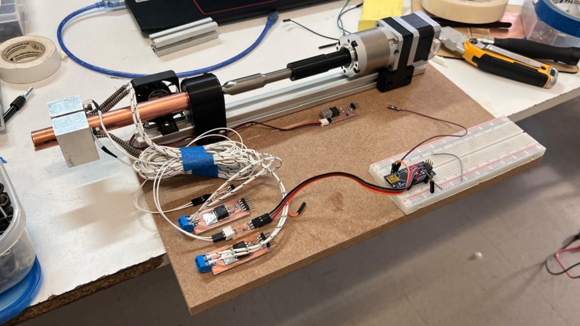
Before starting the project, I conducted several tests and spent a few weeks making progress and testing various aspects, such as in week 14, when I used the interfaces to begin working on the project's electronics.
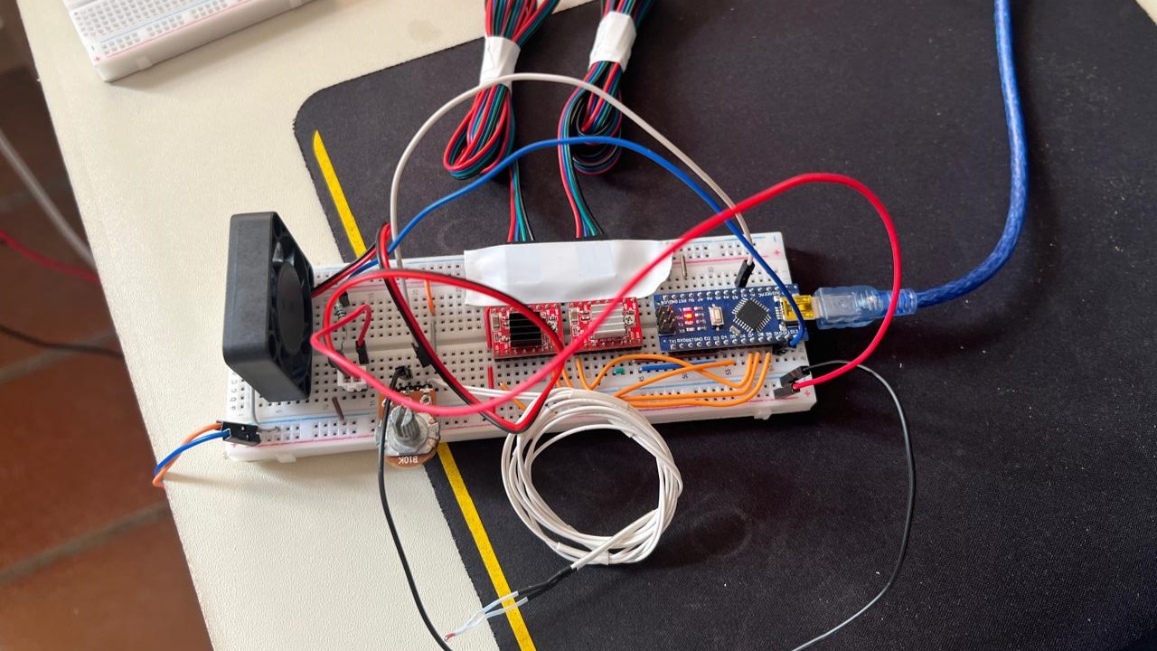
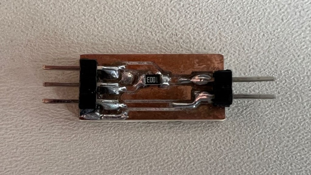
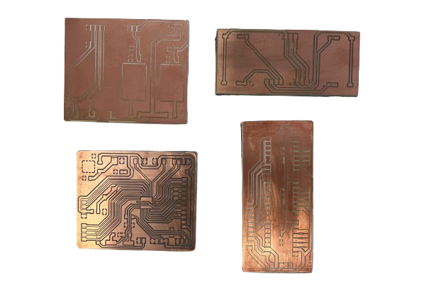
I manufactured several miniature test boards for the temperature system. These boards allowed me to save material and worked perfectly for my tests.
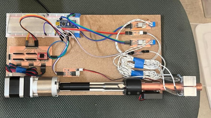
With the board modules I made and some simple 3D prints, I conducted tests for temperature control. These tests were performed using an Arduino, jumpers, and a breadboard.
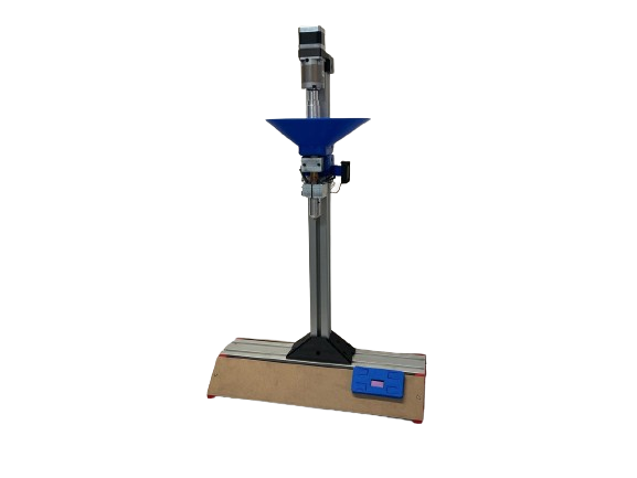
3d model
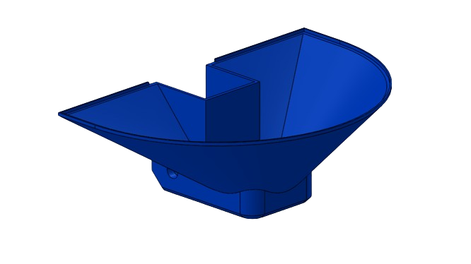
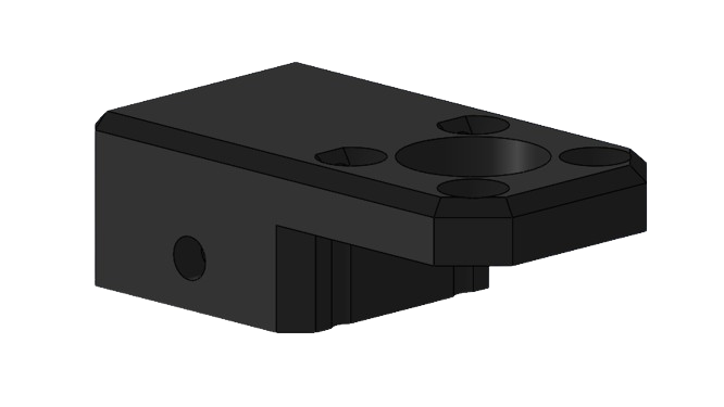
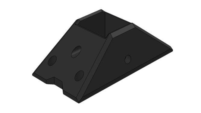
Here you can see a 3D model of the extrusion system, as well as some of the parts used in the design, such as the funnel where the material is received, the upper support that holds the motor and the reduction system, the support that holds the aluminum profile (more details in week 3), and a floor support used to support the MDF that covers the electronics and the power supply. To see the entire model, download it here ALL FILES.
electronic
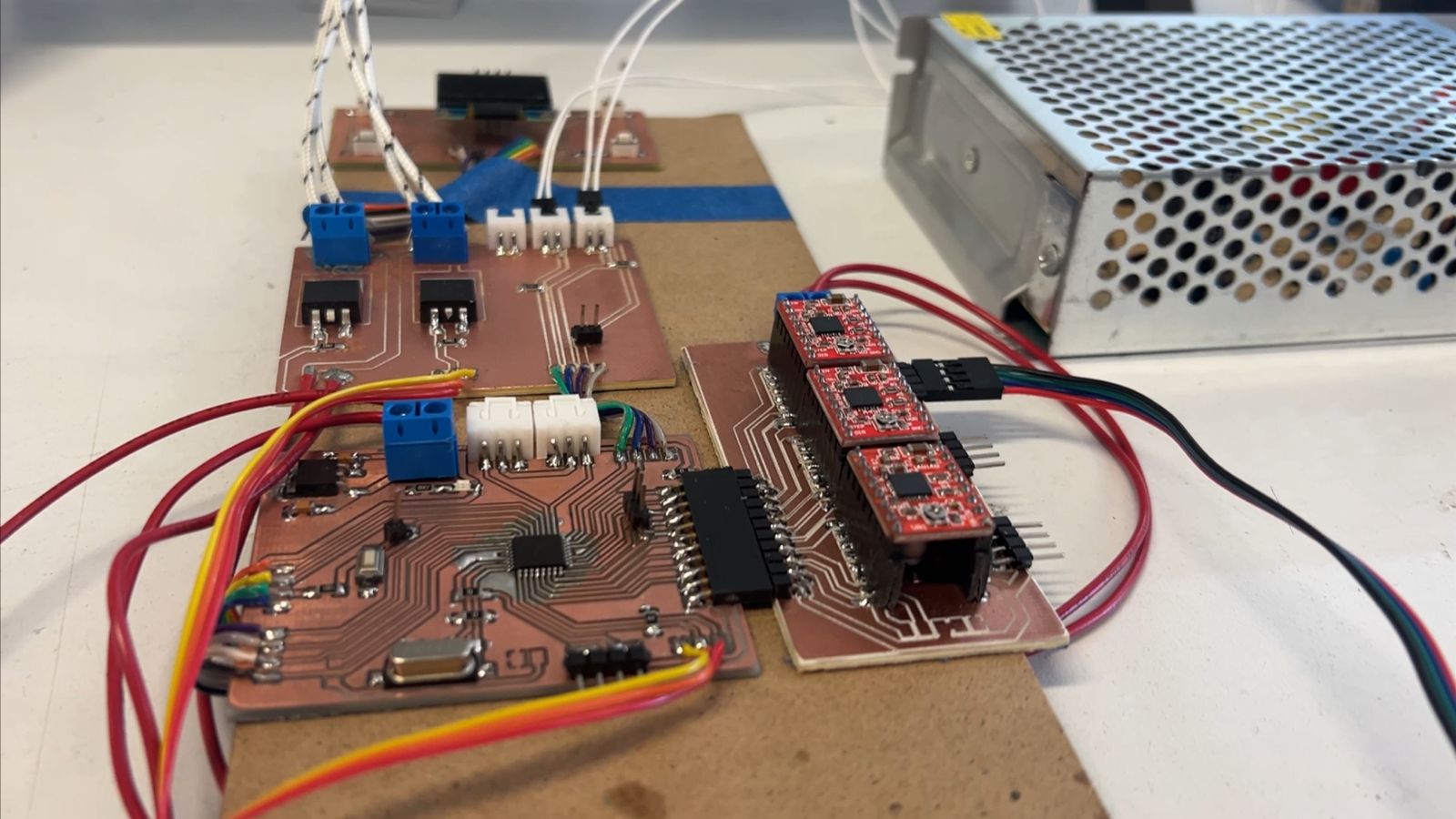
The idea for designing the boards is to create separate boards by modules. This way, I can use the modules and run tests before having to manufacture a complete board. The plan is to manufacture four different boards. One will house the microcontroller and all its outputs. Another will be for temperature control. The third will be for the motor drivers. And finally, a board where I can place the screen and buttons for control.
design
principal pcb
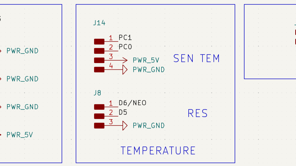
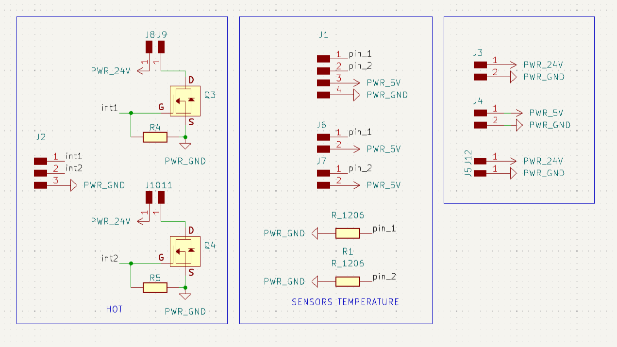
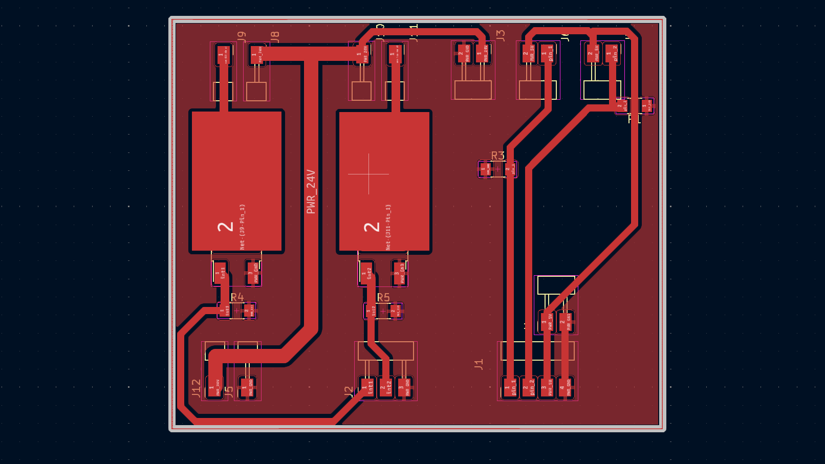
This is the schematic of the main board where my microcontroller will be, which will control the entire system. The schematic is divided into sections, each labeled with its name. You can see all the output pins for connecting the secondary boards.
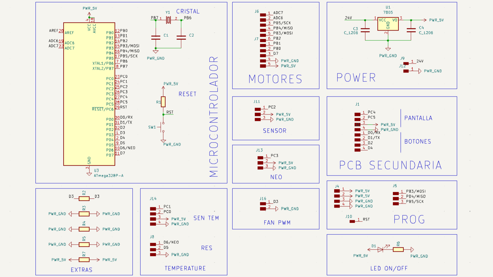
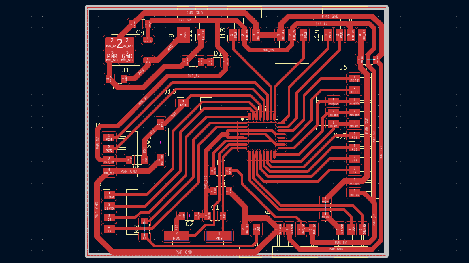
Here you can see how all the tracks will be arranged and how the main board with our ATmega will be distributed. The microcontroller is in the center, on the right side are the output pins for the motors, at the bottom are the outputs for a digital pin, power pins, and the fan pin, as well as the crystal required by the ATmega. On the left side is the output for the secondary PCB. In the upper left part is the voltage regulator with a 5-volt output, and at the top are the pins for connecting the temperature control board.
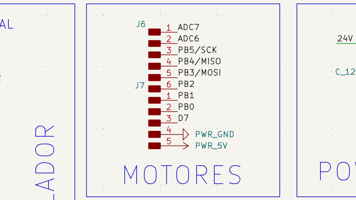
MOTOR PCB
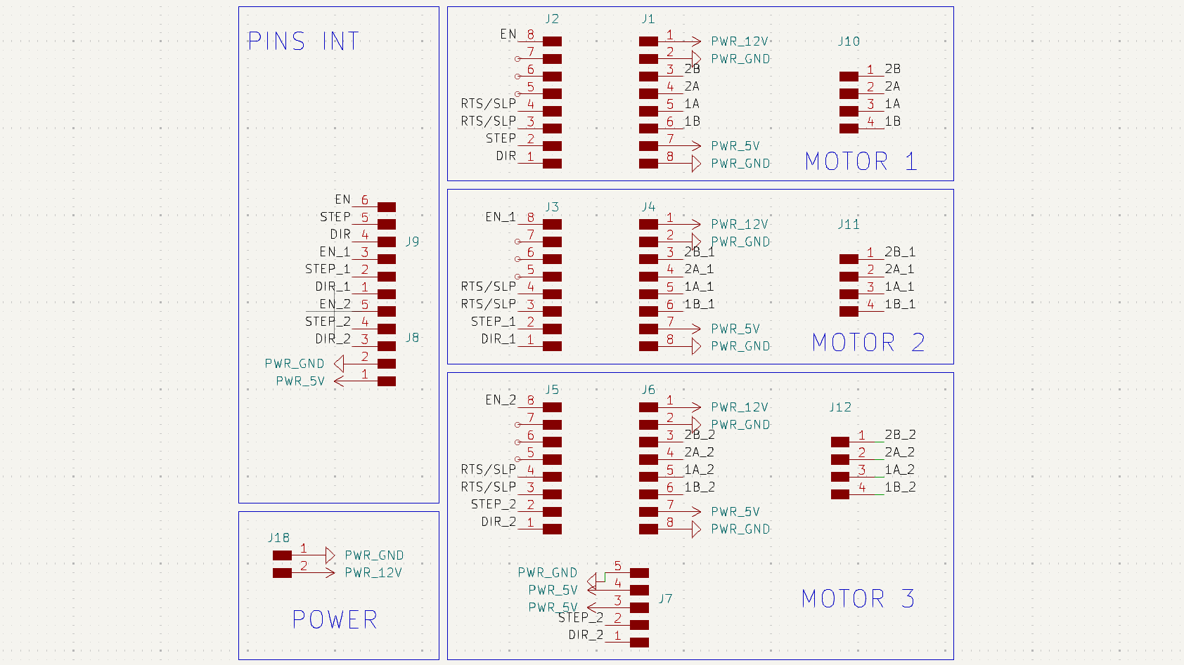
This is the schematic of the board where the drivers for controlling the NEMA motors will be installed. On the left side, you can see all the pins where the three pins for each driver are connected: Enable, Step, and Dir. On the right side are the output pins to connect the drivers. The last driver has an output pin to control a motor with a larger external driver.
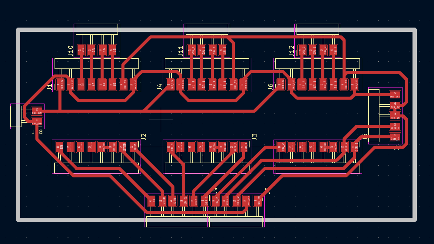
This is the design of the board to control the motors. At the bottom, you can see all the output pins that will connect to the main board. In the center, there are the pins where female headers will be placed to insert the drivers. At the top is the output to connect the motors to each driver. On the left side is the 12V or 24V power supply input. On the right side is the output for an external driver.
HEATING PCB
This is the heating board that will control the temperature of our extrusion system. In the board design, on the right side, you can see the two modules, the larger parts where the transistors will be placed to control the activation of the ceramic resistors. On the right side are the tracks where the thermistors will be connected, which will read the temperature.
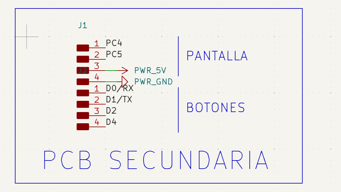
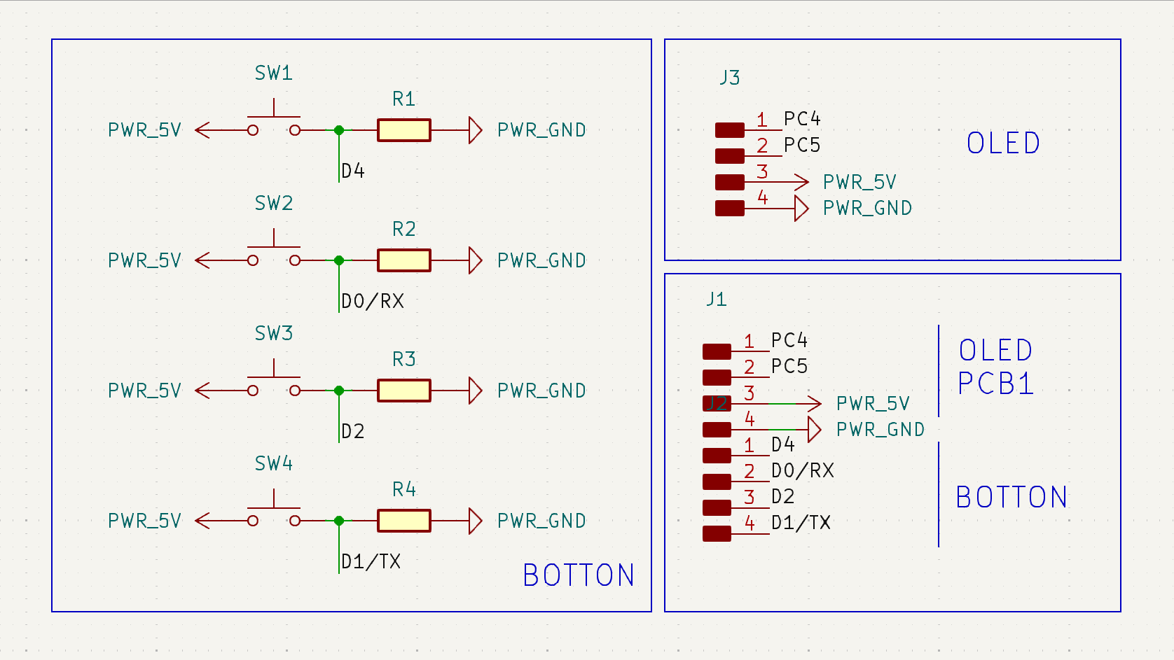
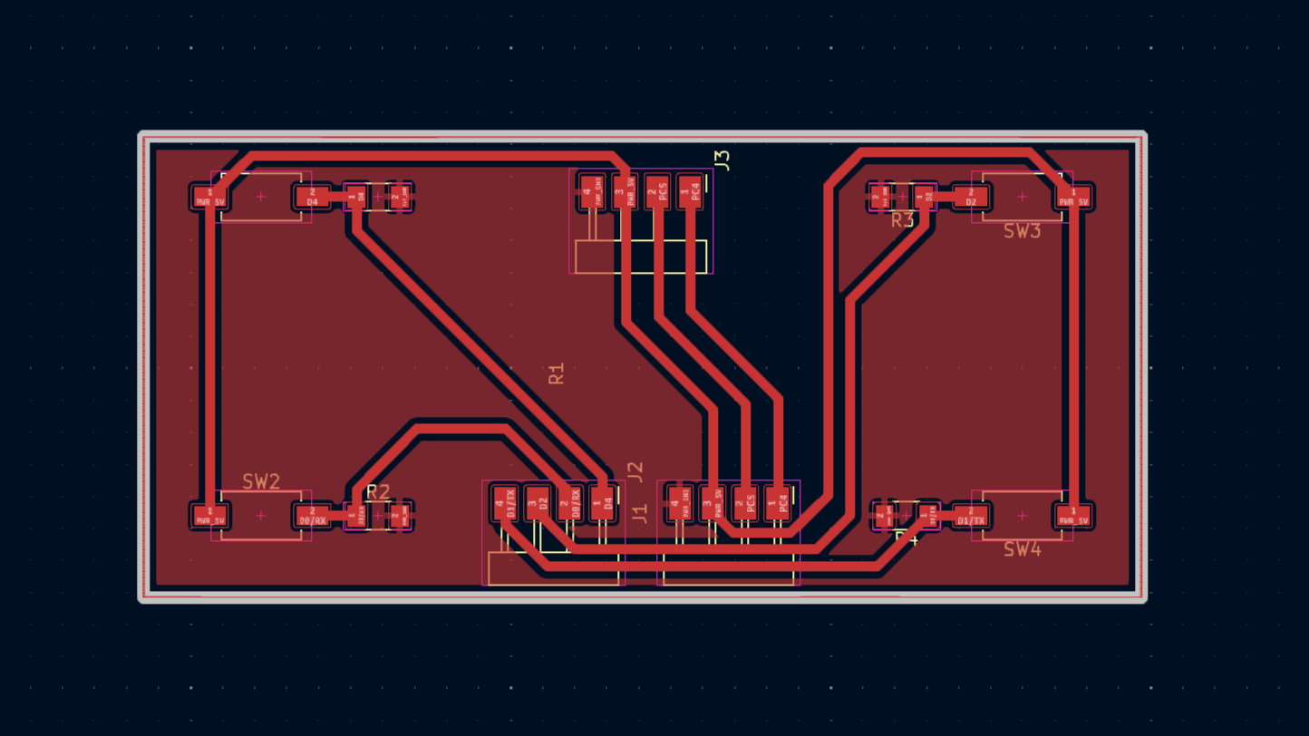
OLED pcb
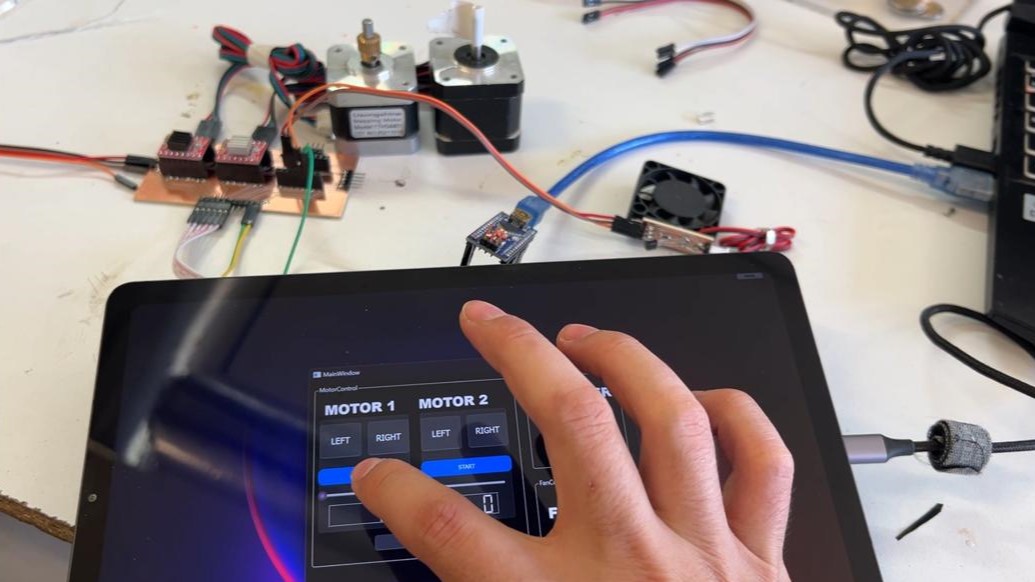
This is the secondary board, which features an OLED screen and four buttons. This screen will be used for extrusion control.
manufacturing
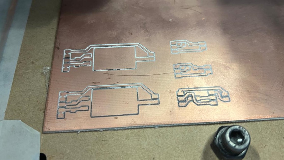
For the PCB manufacturing process, the same procedure used throughout the weeks was followed. This is explained in more detail in week 4. It started by placing copper plates inside the machine for etching and cutting the boards. With patience, components were soldered one by one until all the boards were completely soldered and assembled. The advantage of these boards is that they come in modules, making the manufacturing process easier. If there's a problem or a mistake, only a module needs to be replaced, not the entire board.
aluminum manufacturing
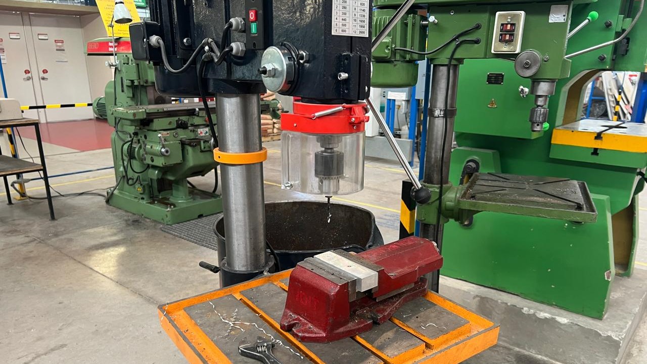
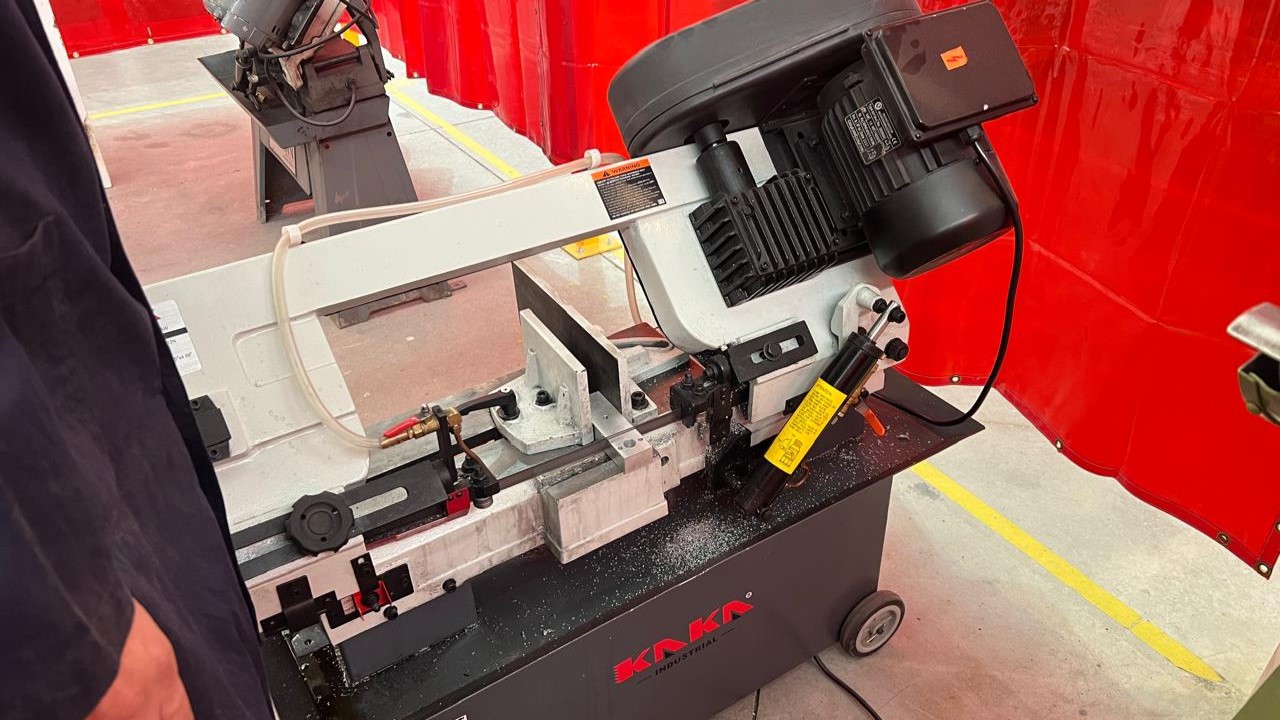
Here you can see the parts I made for the extrusion system. These parts were manufactured using the tools available at the Ibero Puebla workshop: lathe, bench drill, band saw, and milling machine.
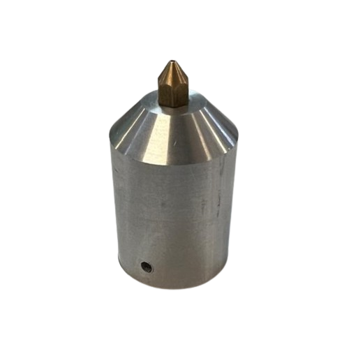
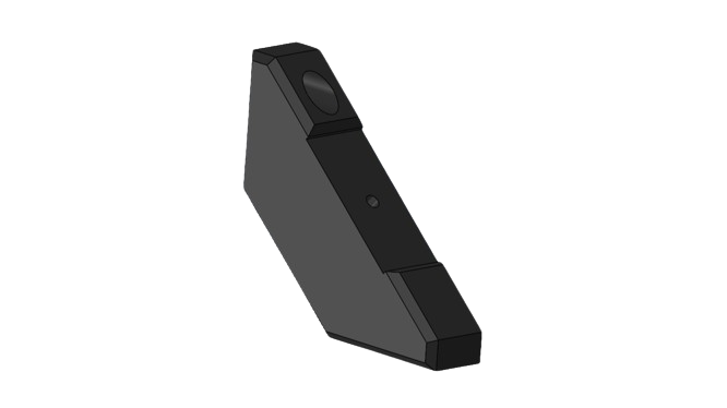
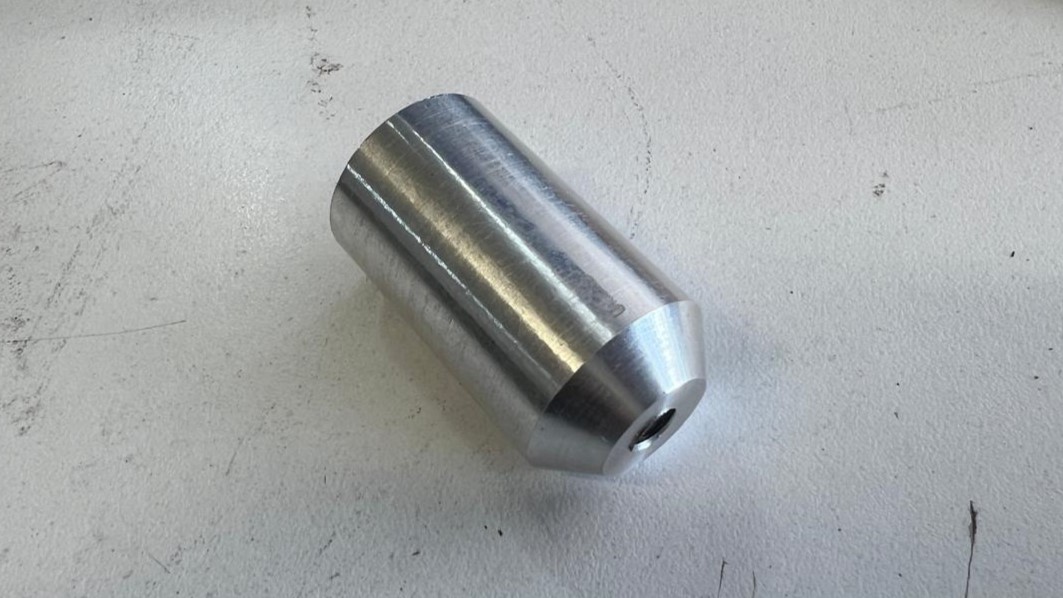
nozzle
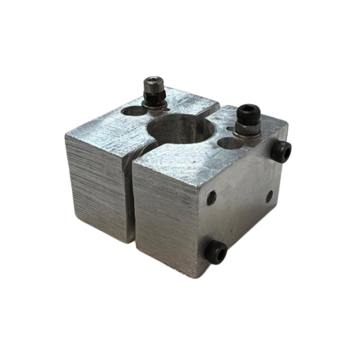
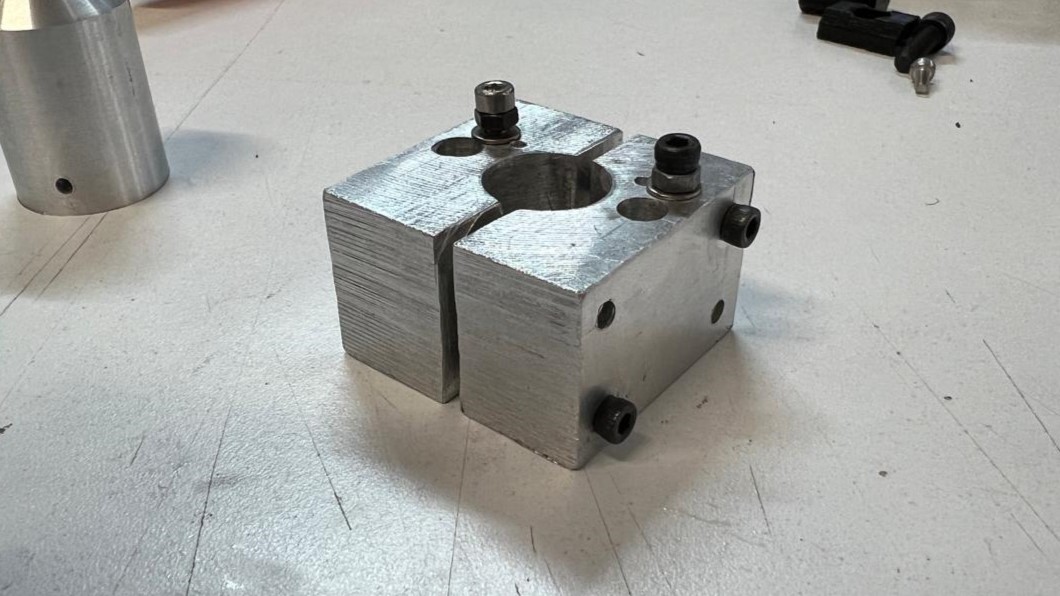
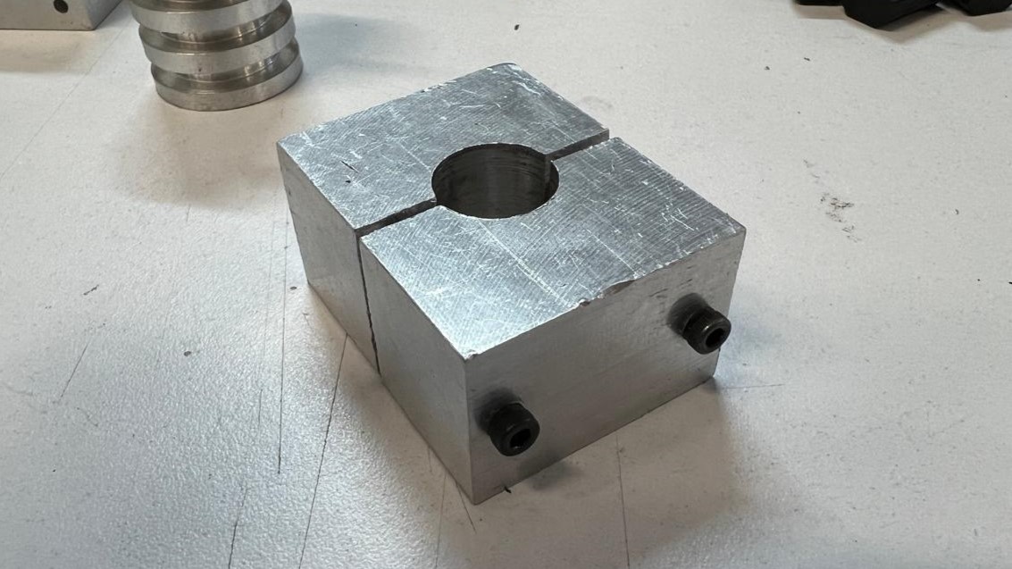
heater block
support
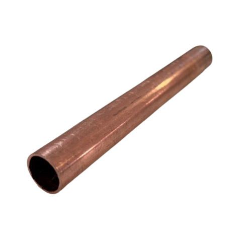
tube
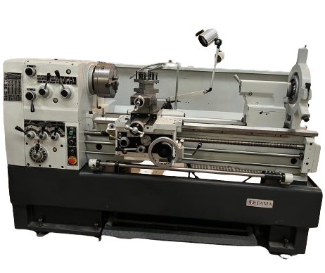
Lathe
A lathe is a machine tool that shapes solid materials like metal, wood, and plastic by rotating the workpiece and applying a cutting tool. Its main functions include turning, boring, threading, taper turning, cutting, grooving, and facing. It is widely used in the automotive, construction, aerospace, manufacturing, and craft industries, being essential for its versatility and ability to produce parts with high precision and good surface finish.
- Headstock: The part of the lathe where the main motor and gears that drive the main spindle are located.
- Main Spindle: The main axis that rotates and to which the workpiece is attached via the chuck.
- Chuck: Also known as a clamping device, it is used to securely hold the workpiece on the main spindle.
- Tailstock: The part of the lathe located at the opposite end of the headstock. It is used to support the workpiece with a movable center.
- Longitudinal Carriage: The part that moves along the longitudinal axis of the machine and supports the cross slide and tool post.
- Cross Slide: Moves perpendicular to the longitudinal carriage and supports the tool post.
- Tool Post: The part that holds the cutting tools and allows their adjustment for various machining operations.
- Turret Tool Post: Allows for the placement of multiple cutting tools that can be quickly interchanged during machining.
- Lathe Bed: The surfaces on which the longitudinal and cross carriages move. Ensures linear and precise movement.
- Control Handwheels: Manual mechanisms that allow the movement of the longitudinal and cross carriages.
- Gearbox: Contains the gears that allow for varying the speed and feed of the spindle and carriages.
- Foot Brake: Used to quickly stop the spindle's movement.
nozzle
For the nozzle, I started with a solid one-inch aluminum bar. Using different drill bit sizes, I created holes along the piece. With a roughing tool, I began removing material until I reached the desired diameter. With the help of the turret, I made an inclination to give the piece a slight angle. Using the cutting tool, I removed the complete nozzle piece. After turning it over, I used a 16 mm drill bit to achieve the measurement for the copper tube. This drill bit did not go through the entire nozzle.
I used an M6 tap to thread the piece and attach a 3D printer nozzle. Additionally, with the help of a bench drill, I made a hole to later use an M3 tap and place set screws to ensure the piece stays in place.
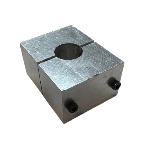
HEATER BLOCK and SUPPORT
For the heating block and the support, I used a rectangular piece of aluminum that was available at the university. With the help of a bench drill and different drill bit diameters, I created holes in the piece. This allowed the copper tube and M3 screws, which I would use to tighten them, to pass through.
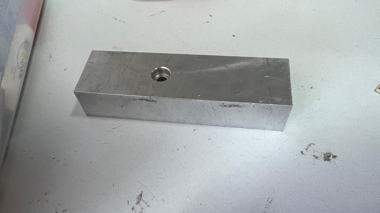
With a band saw, I cut the entire aluminum block to extract my piece.
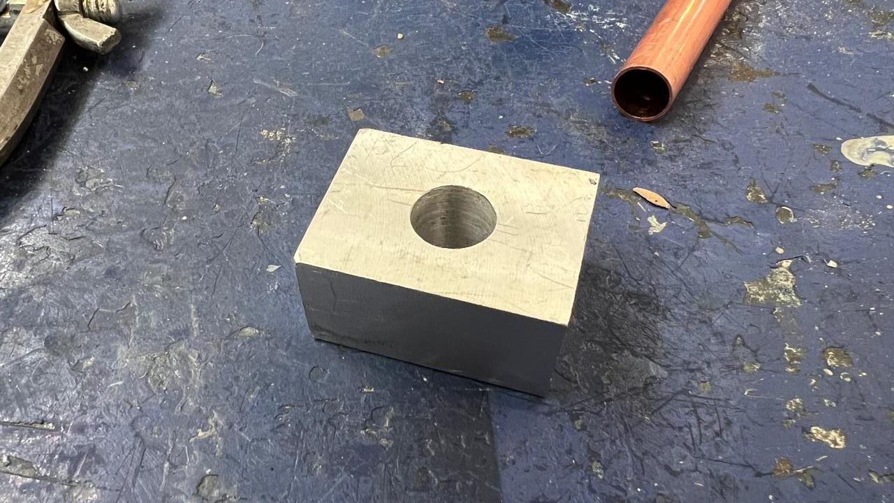
Here you can see the final result of the heating block and the support.
aluminum profile
For the aluminum profiles, I used the band saw to cut them and the milling machine to straighten them.
code
- Include Library:
#include <PID_v1.h>- This line includes the PID library for controlling the temperature. - Pin Definitions: The pins for the thermistor, heater, stepper motors, and fan are defined.
- Constants for Motor Control: Defines the steps per revolution and the delay between steps.
- Variables for Timing and State: Variables to keep track of timing for stepping and temperature updates.
- PID Parameters: Defines the desired setpoint, input, output, and PID constants (Kp, Ki, Kd).
- Thermistor Variables: Constants for the thermistor calculations, including beta constant, room temperature in Kelvin, and nominal resistance.
- Setup Function: Initializes the serial communication, sets the pin modes, configures the PID, and sets the initial direction of the motors.
- Loop Function: Continuously calls functions to control motors, temperature, fan, and print status.
- Motor Control Functions: Each function (
controlMotor1,controlMotor2,controlMotor3) controls the stepper motors by toggling the step pin state at the specified delay. - Temperature Control Function: Reads the thermistor temperature, updates the PID, and controls the heater element.
- Fan Control Function: Controls the fan speed based on temperature.
- Print Status Function: Prints the temperature and other values to the serial monitor at specified intervals.
final