4. Electronics Production
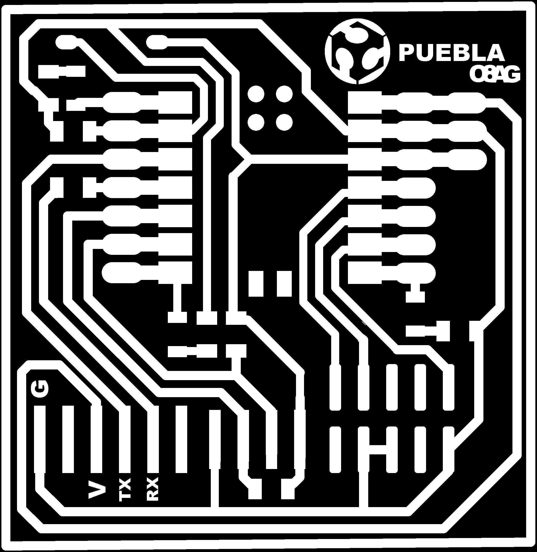
This week is all about electronics; we were asked to build a PCB and solder its components. For this task, we were provided with the etching and cutting template of the PCB. The purpose of this PCB is to create a programmer that we will be using in future electronic practices and for our project. Essentially, this week we will focus solely on the construction, soldering, and functional testing of the PCB, without designing any circuits since the goal is to introduce us to PCB design. And how will we manufacture the PCB? First, I'll explain what a PCB is and how it works. PCB?
what is a PCB?
A PCB (printed circuit board) is an integrated circuit where components and conductors are embedded within a mechanical structure. This structure consists of alternating layers of conductive material, like copper, and laminated insulating material. During manufacturing, copper layers are etched to create traces that connect the circuit's components. Finally, electronic components are added to the outer layers using automated or manual assembly techniques and are soldered onto the board. The board is completed with a solder mask and a silkscreen for component identification.
Now that we know what a PCB is, I will explain the type we will use and the machine we will operate.
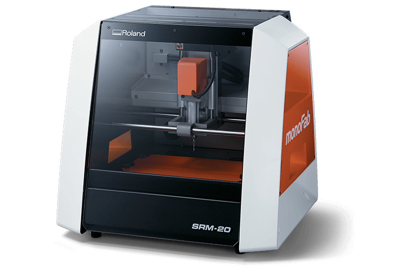
CNC MILL
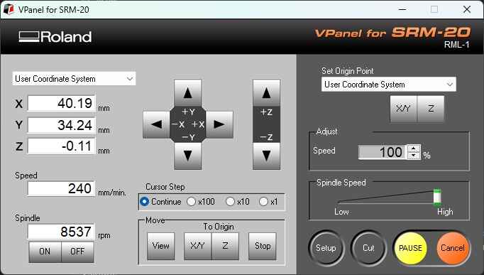
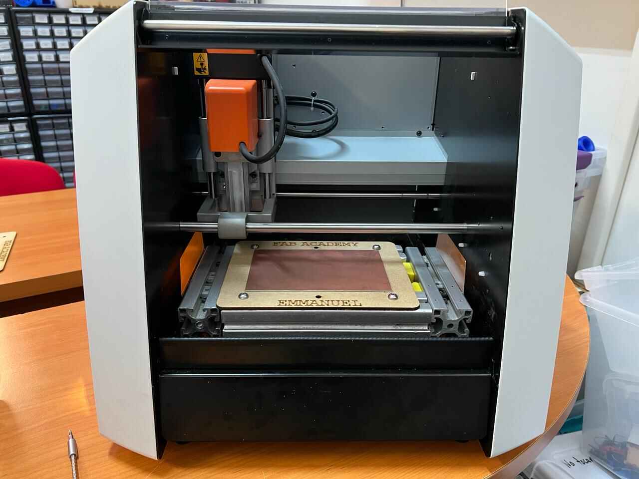
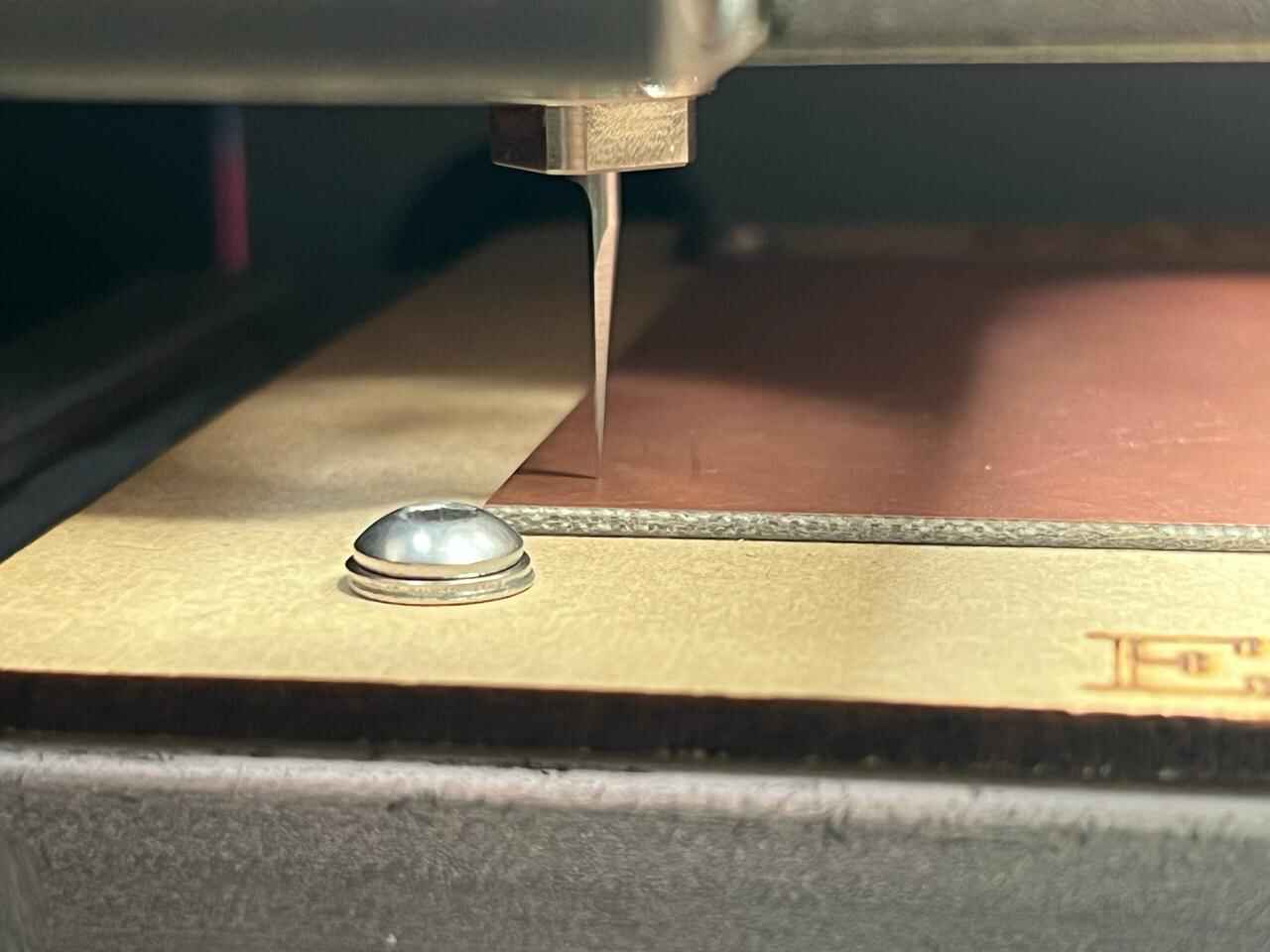
The machine we will use for this practice is the Roland SRM-20. The features of this machine can be found on the GROUP PAGE .
Roland SRM-20
- Manufacturer: Roland
- Model: SRM-20
- Specifications: 203x152x60 mm, 1800 mm/min, 0.001 mm/step, 7,000 RPM
- Applications: Precision three-axis machining, including PCBs down to 0.25 mm feature size, and machinable wax to make tooling for molding and casting
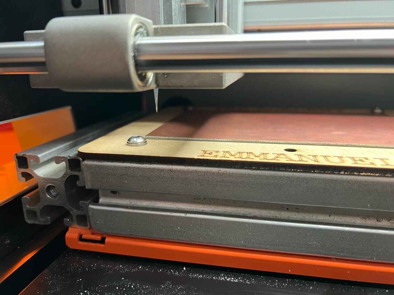
CUT TOOLS
To manufacture the plates we use the following cutting and engraving tools:
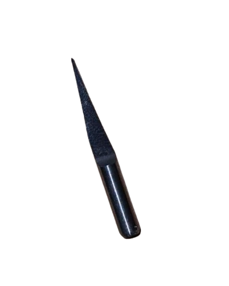
Engraving bit
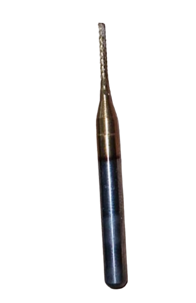
milling cutter 1mm
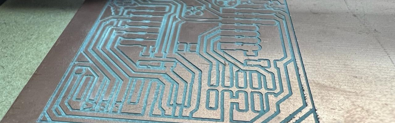
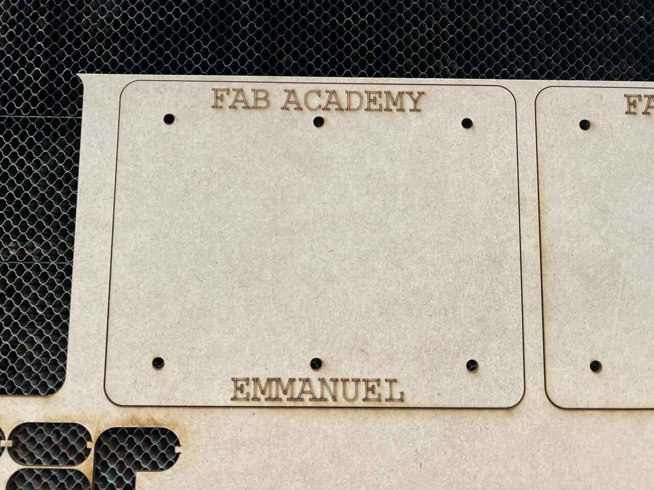
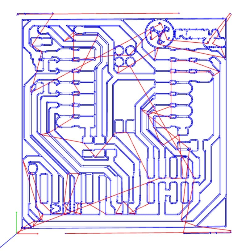
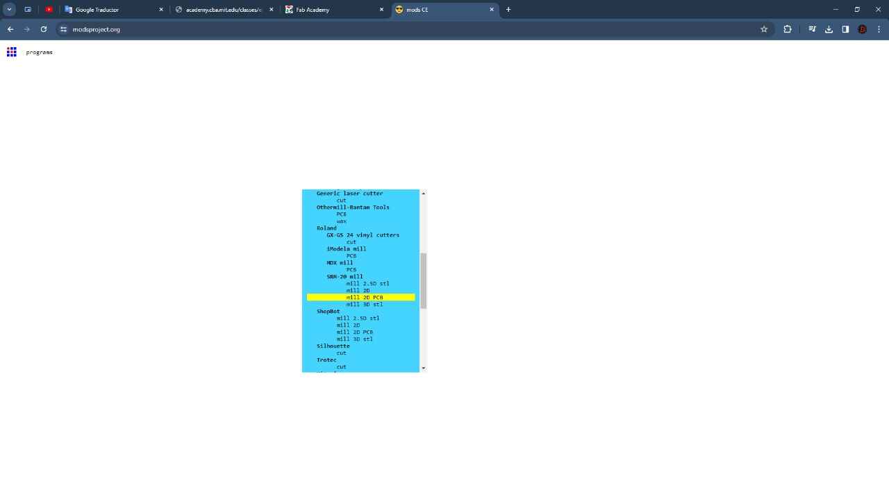
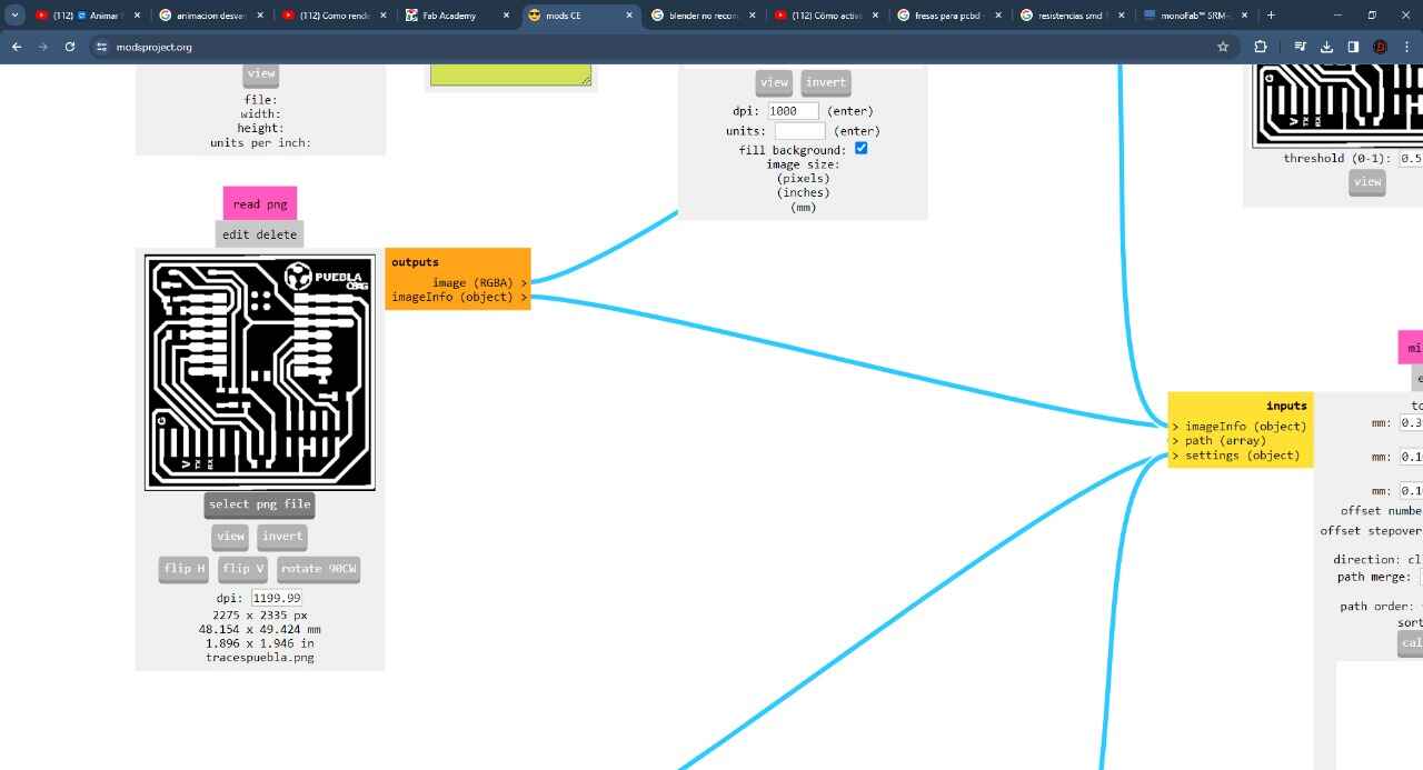
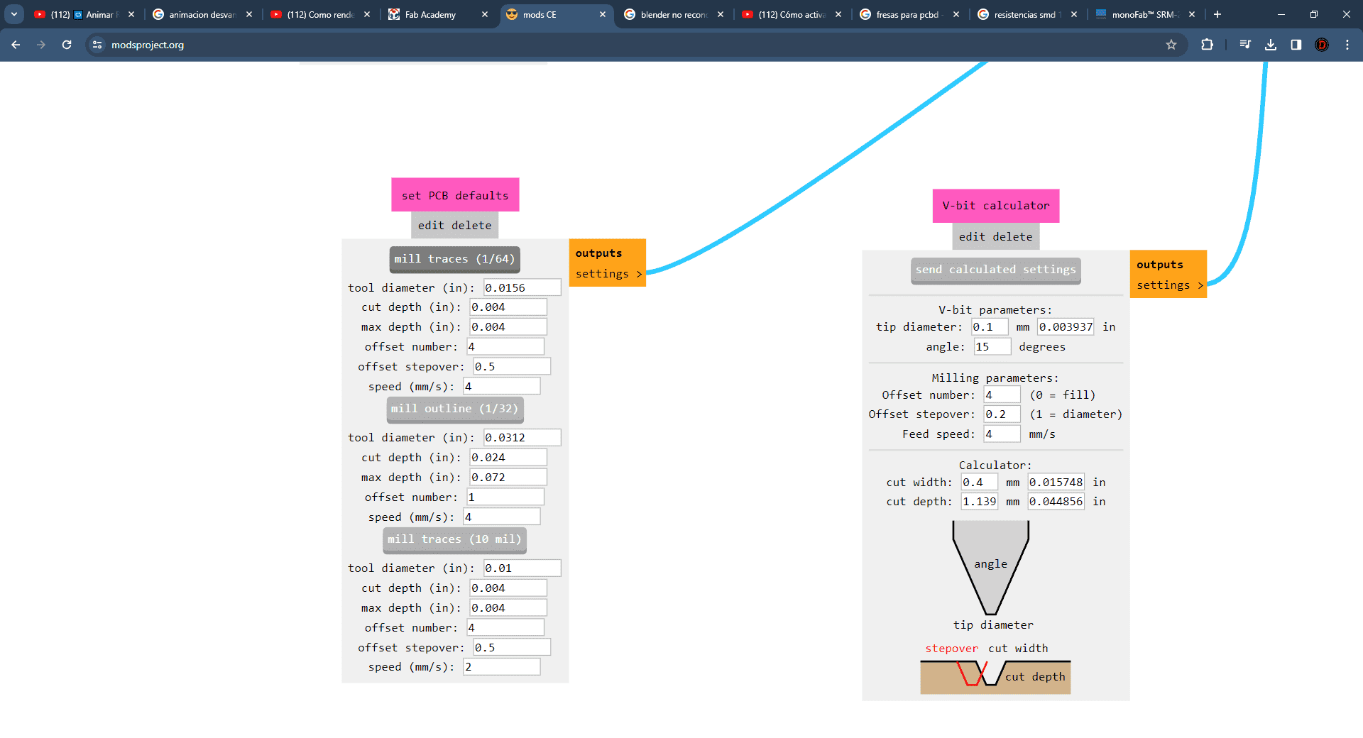
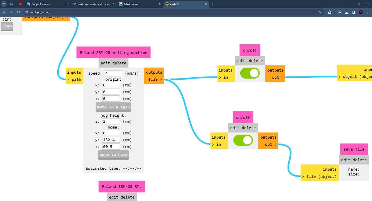
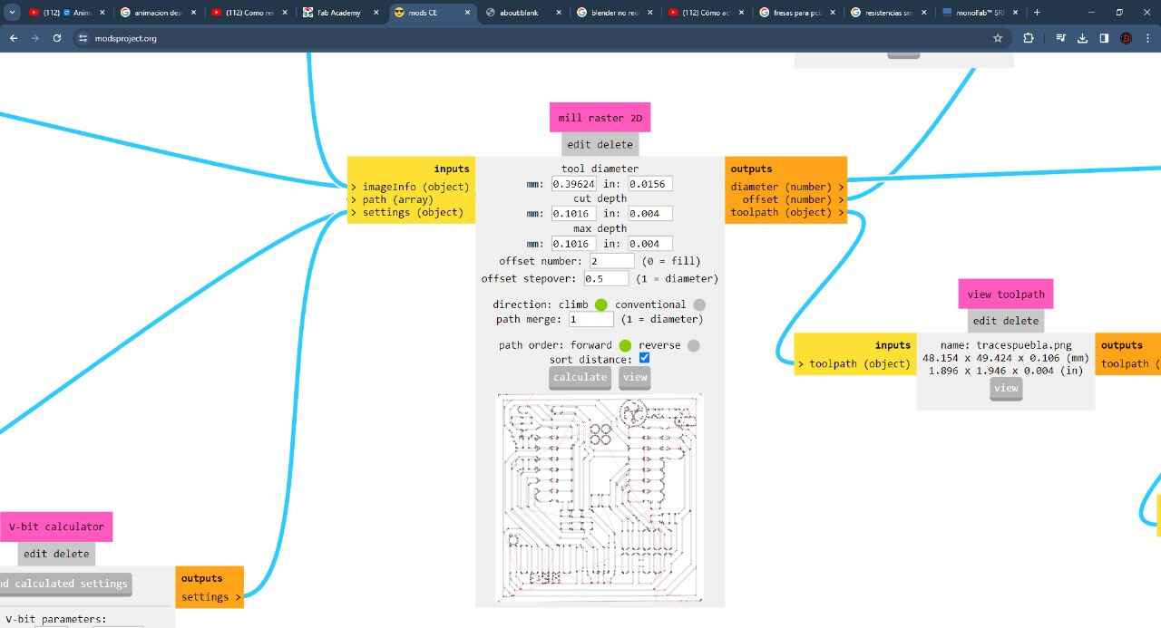
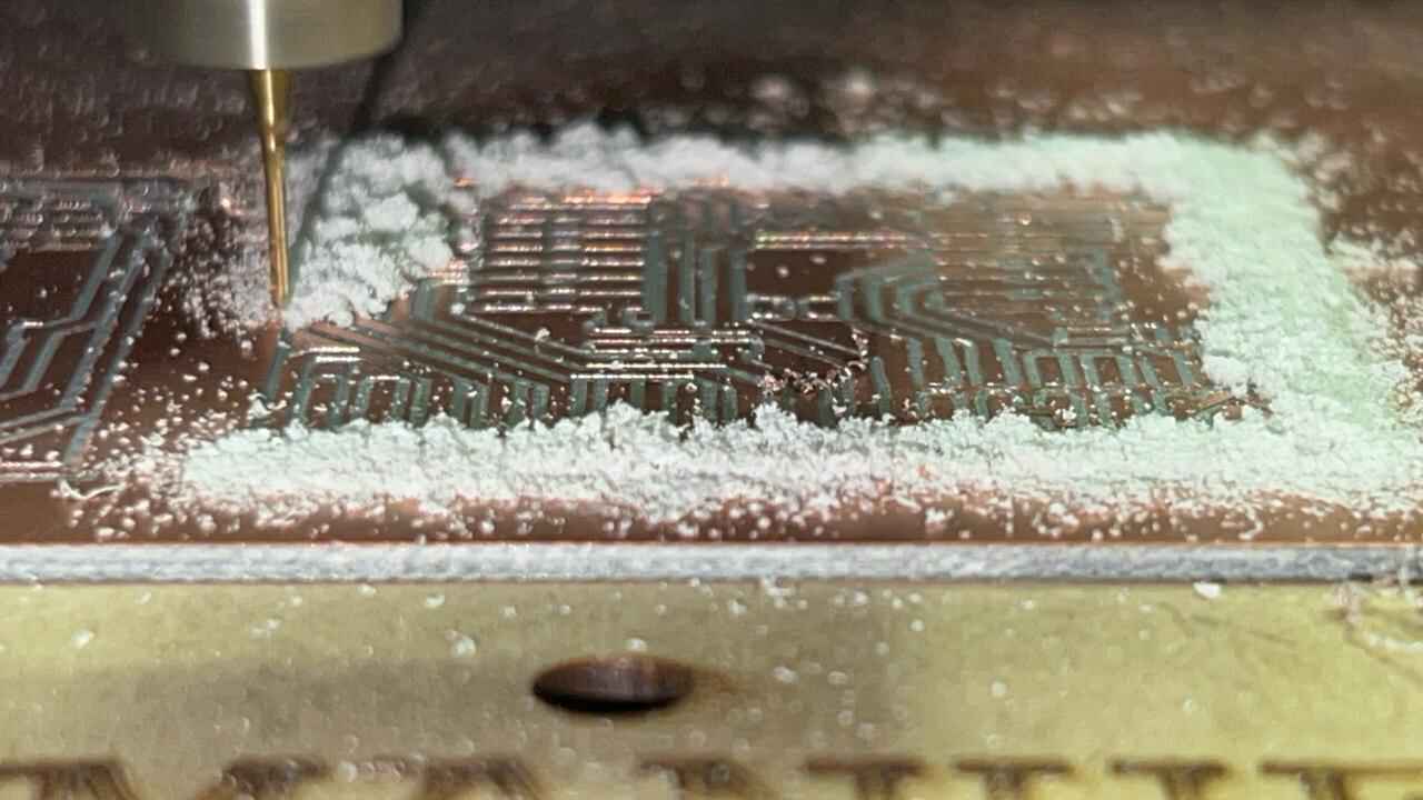
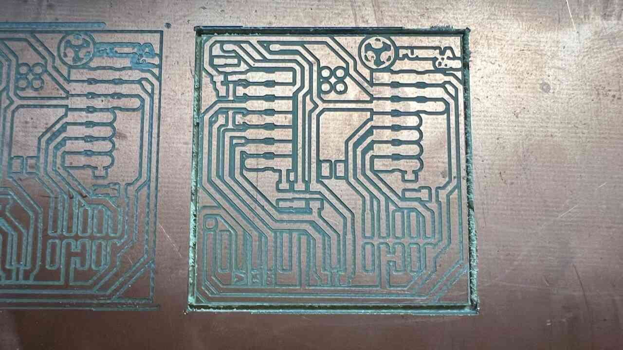
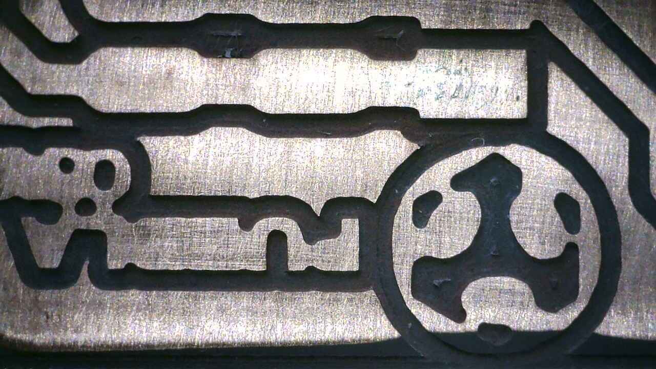
PCB FABRICATION


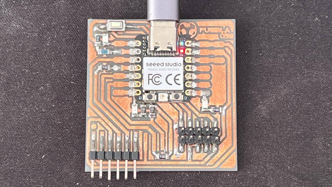
SOLDERING
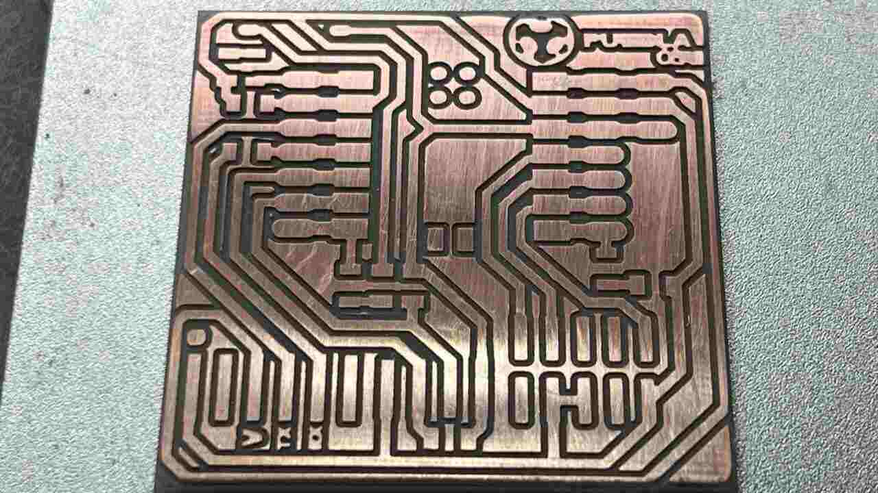
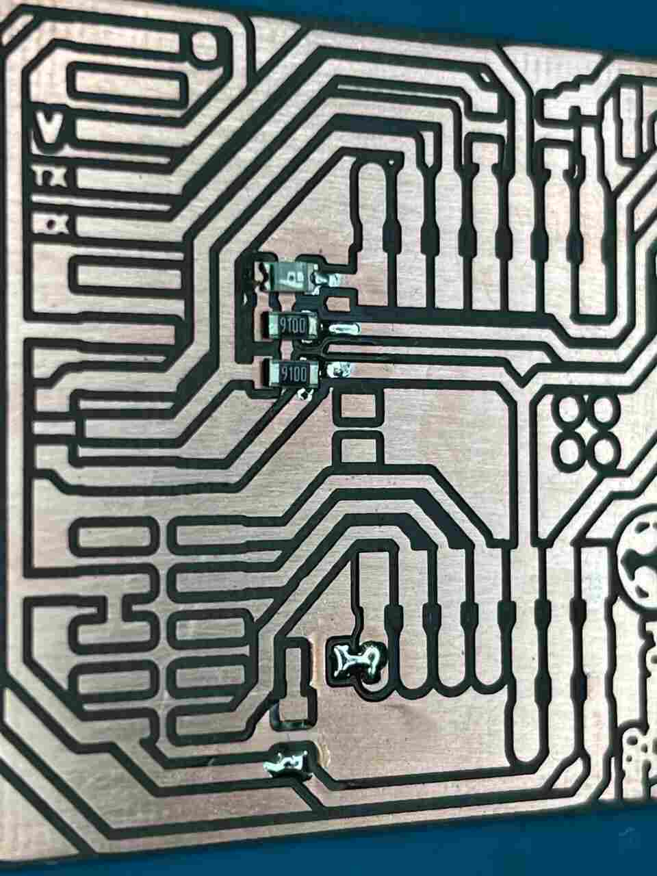
- For the soldering process, first, I will need to sand the PCB to make it shiny and smooth.
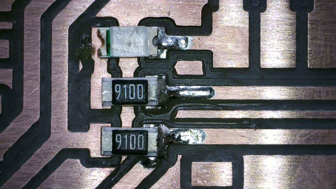
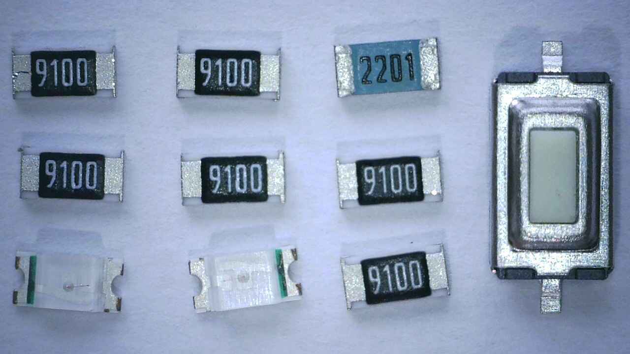
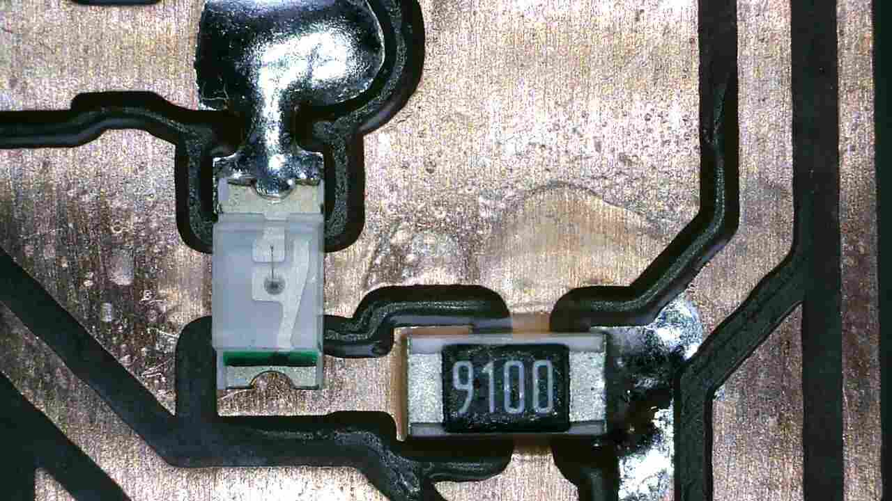
- Using the photos and diagrams provided, I identified where each component goes and in what orientation.
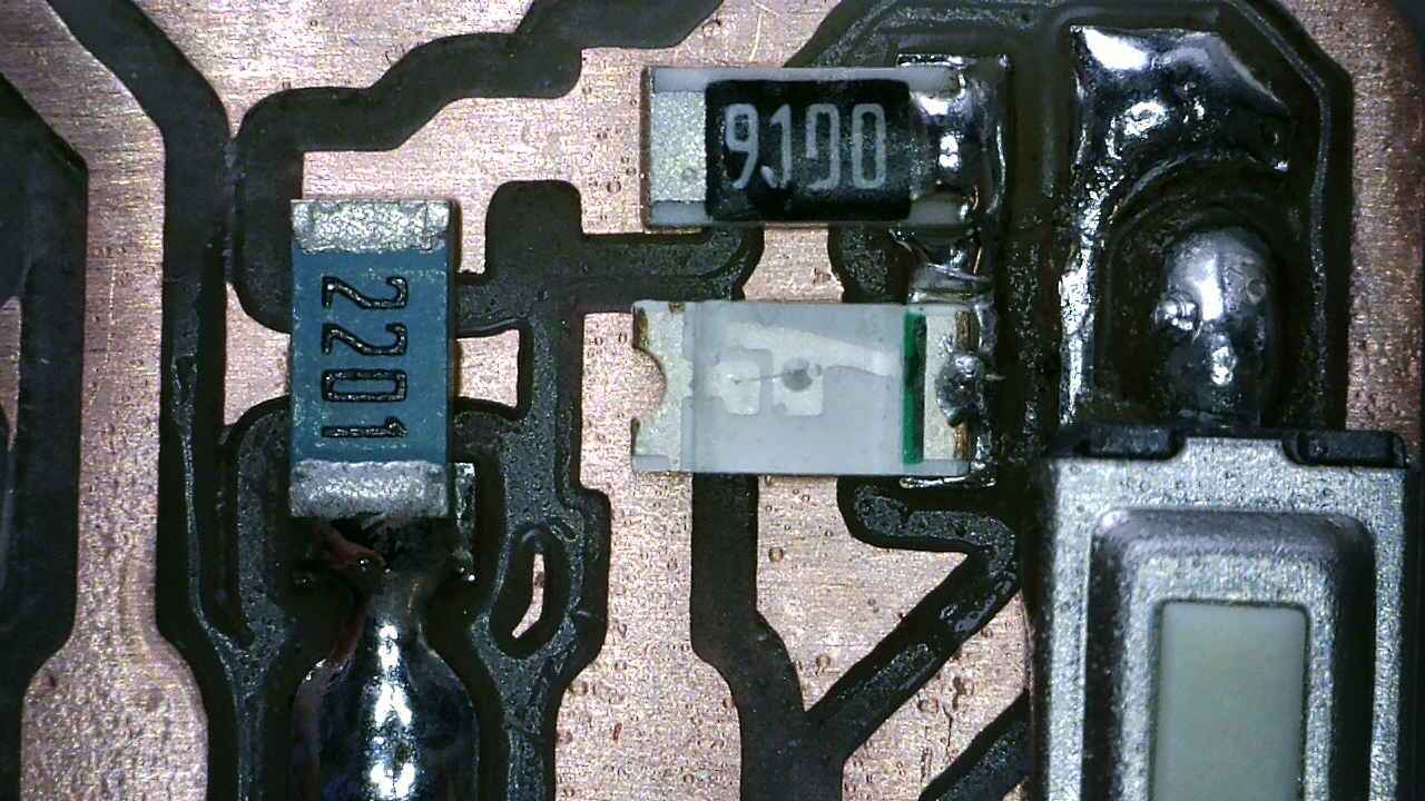
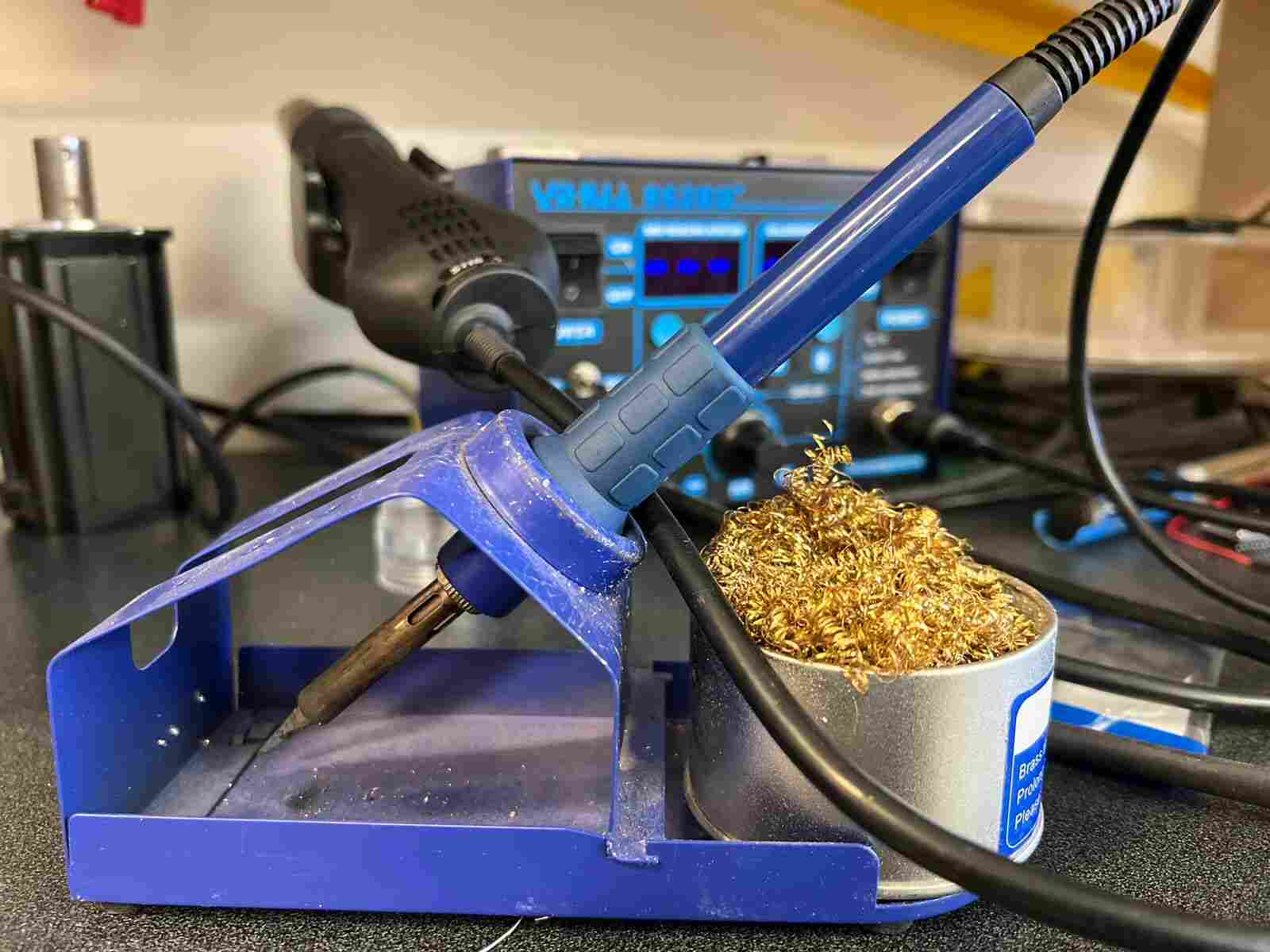
- Using the soldering iron at 370 degrees, I placed a solder dot on each site for a component.
- With the help of small tweezers, I held the components to be able to solder them at the solder point already made.
- In this way, I soldered all the components until obtaining the final board.
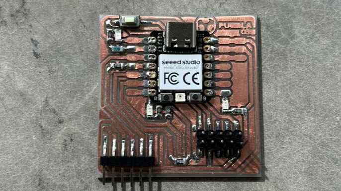
TEST RUN
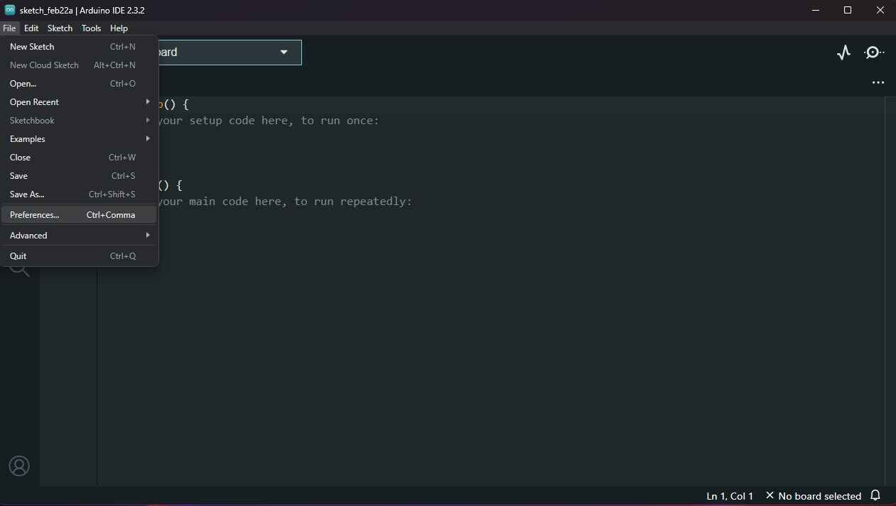
To test that our PCB works, we'll need to upload a code. We will use the Arduino program to upload the code. To install it, we have to visit its website and download it. In the main window of Arduino, we'll enter the File menu, then Preferences.
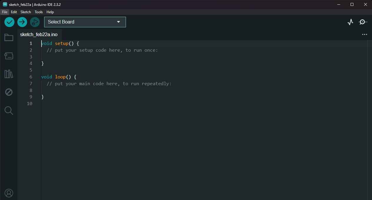
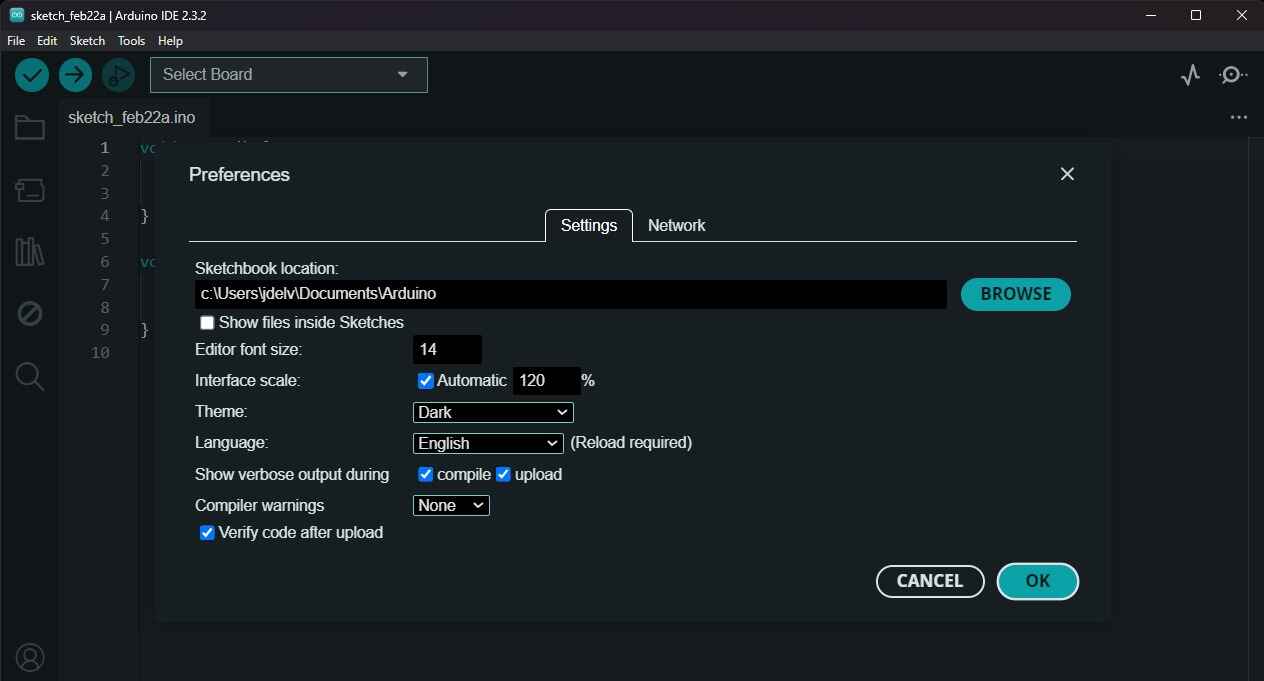
In the lower part of the Preferences, we will paste the following link () and close the window. A download will start. In the "Select Board" section, we will search for the Seed Xiao RP2040 and download the board extension. Next, we will enter the code provided to us, connect our board, and upload the code.
The code we will upload will intermittently light up the two lower LEDs, and the top one will only light up when we press the top button. Blink code