9. Output Devices
For this week's development, we were asked to implement outputs or output devices. In my case, I will be using an OLED display and a servo motor. I will use the same board I developed last week, as the purpose of that board was to conduct tests and use it for future weeks. First, I will explain a bit about what outputs are and what types of outputs exist. Additionally, I will explain how the components I am going to use work.
Output
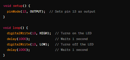
Digital outputs can be in one of two states: high (HIGH) or low (LOW), which corresponds to a high voltage (typically 5V in most Arduino boards) or a low voltage (0V). They are used to turn devices on and off, such as LEDs, relays, and motors. Digital outputs can also send pulses to control devices like servomotors or blinking LEDs. For more information GROUP PAGE .
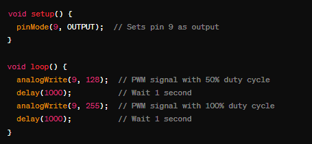
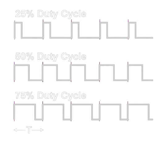
PWM outputs allow simulating an analog signal using a digital signal that rapidly switches between high and low states. This technique controls the amount of power delivered to a device by varying the width of the pulses in a given time period. PWM outputs are used to control the speed of motors, the brightness of LEDs, and other devices that require a variable analog signal. By adjusting the duty cycle (the percentage of time the signal is high within a cycle), PWM can effectively manage devices that need varying levels of power.
materials
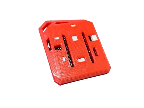
- Development Board made in week 8
- OLED screen
- Servomotors
- Potentiometer
component operation
I will briefly explain how the components I am going to use work and their characteristics, along with some examples.
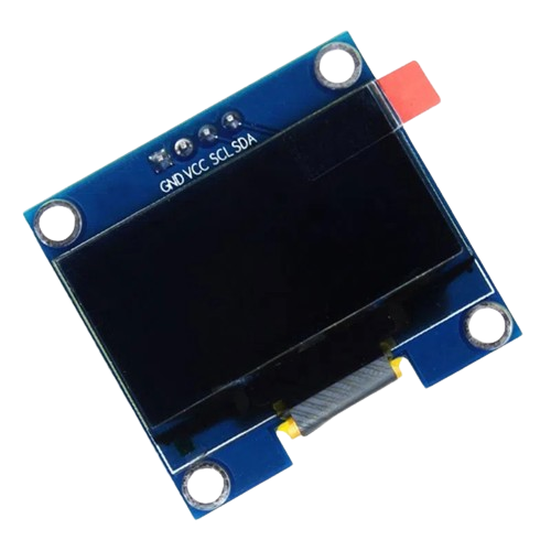
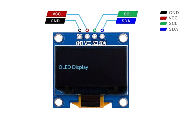
OLED screen
The SSD1306 OLED screen is widely used in various microcontroller projects, including platforms like Arduino, Raspberry Pi, and ESP8266/ESP32. It is also ideal for wearable devices due to its low power consumption and compact size. It is used in indicators and meters to display critical information such as temperature and voltage.
- Technology: OLED, no backlight needed.
- Resolution: 128x64 or 128x32 pixels.
- Controller: SSD1306.
- Interface: I2C and SPI.
- Size: Between 0.96 and 1.3 inches.
- Power consumption: Very low.
- Color: Monochrome (white, blue, or yellow).
Features
The SSD1306 OLED screen requires specific commands to initialize and configure the controller. It uses I2C or SPI communication interfaces to receive data from the microcontroller. Each pixel on the screen can be controlled individually, allowing for high precision in graphic representation. Using libraries such as Adafruit_SSD1306 and U8g2 significantly simplifies the process of drawing and controlling pixels.
OLED screens are used in a wide range of technological devices. They are popular in mobile devices like smartphones and tablets for their high image quality and energy efficiency. In televisions, they stand out for displaying vibrant colors and deep blacks. They are also ideal for wearables, such as smartwatches, due to their compact size and low power consumption.
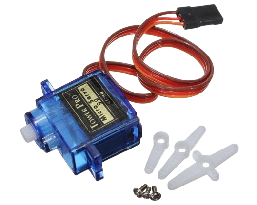
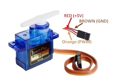
Servo Motor
The MG90S servo motor is widely used in various microcontroller projects, including platforms like Arduino, Raspberry Pi, and ESP8266/ESP32. It is ideal for applications requiring precise control of rotational position, such as robotics, RC vehicles, and mechanical arms.
- Type: Micro servo motor.
- Operating Voltage: 4.8V - 6.0V.
- Torque: 1.8 kg/cm (4.8V), 2.2 kg/cm (6.0V).
- Speed: 0.1s/60 degrees (4.8V), 0.08s/60 degrees (6.0V).
- Control Method: PWM.
- Dimensions: 22.8 x 12.2 x 28.5 mm.
- Weight: 13.4g.
Features
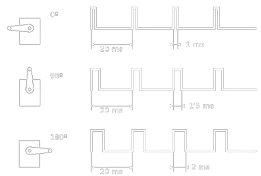
The PWM signal (pulse width modulation) is used to control servomotors like the MG90S through a square wave with an adjustable duty cycle. It operates at a frequency of 50 Hz, repeating 50 times per second. The pulse duration, which ranges from 1 ms to 2 ms, determines the position of the servomotor: 1 ms for 0 degrees, 1.5 ms for 90 degrees, and 2 ms for 180 degrees. This technique allows for precise control of the servomotor's position.
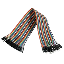
Board and jumpers
The features and functionalities of the board are explained in week 8. The jumpers will be used for the connections between the board and the servomotor. The OLED screen will be connected directly to the board.
code
Before starting with the code, I already had an idea of what I wanted to do. I wanted to be able to move a servo with two buttons that the board has and display the angle on the screen.Before starting with the code, I already had an idea of what I wanted to do. I wanted to be able to move a servo with two buttons that the board has and display the angle on the screen.
Below, you can see the complete code for this practice. Further down, it is detailed and explained how it was done. CODE
Here is a more detailed description of each part of the code.
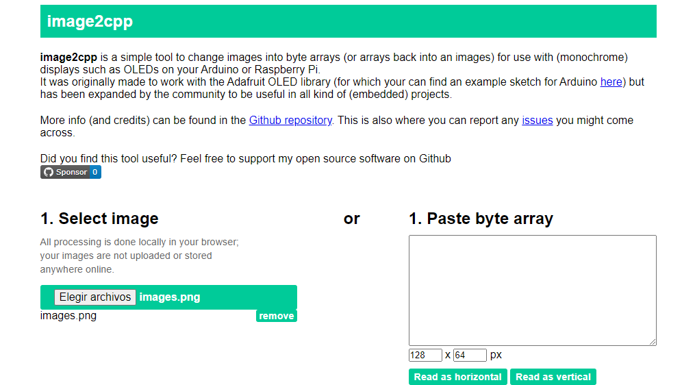
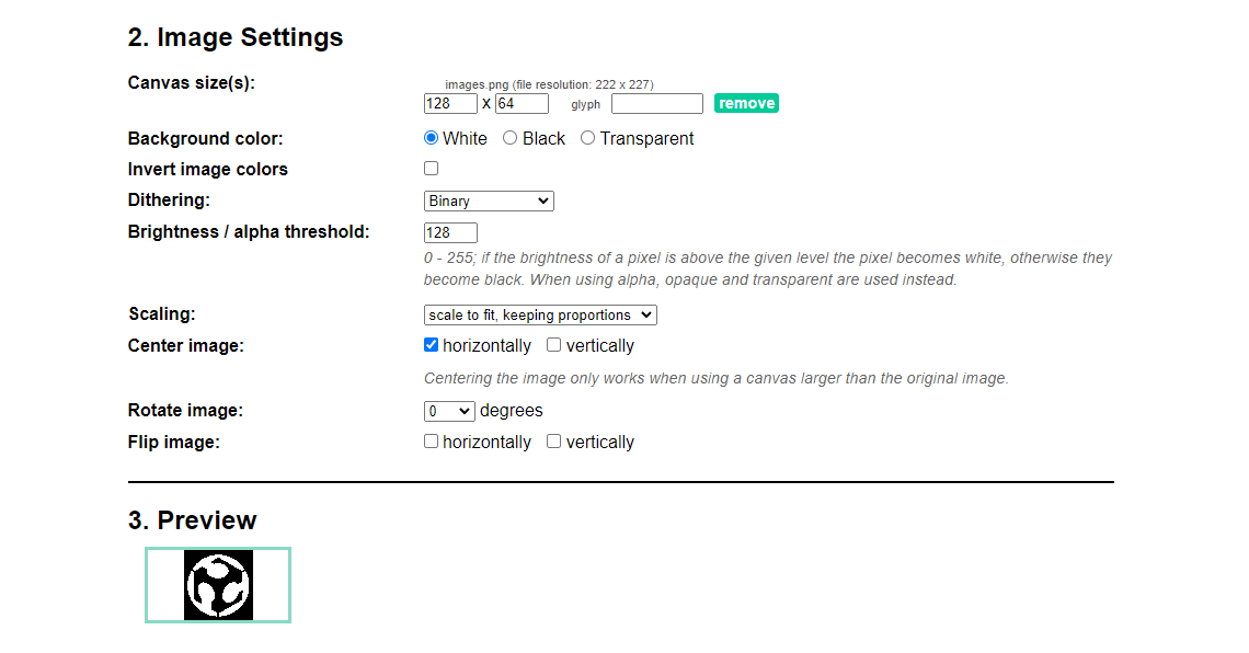
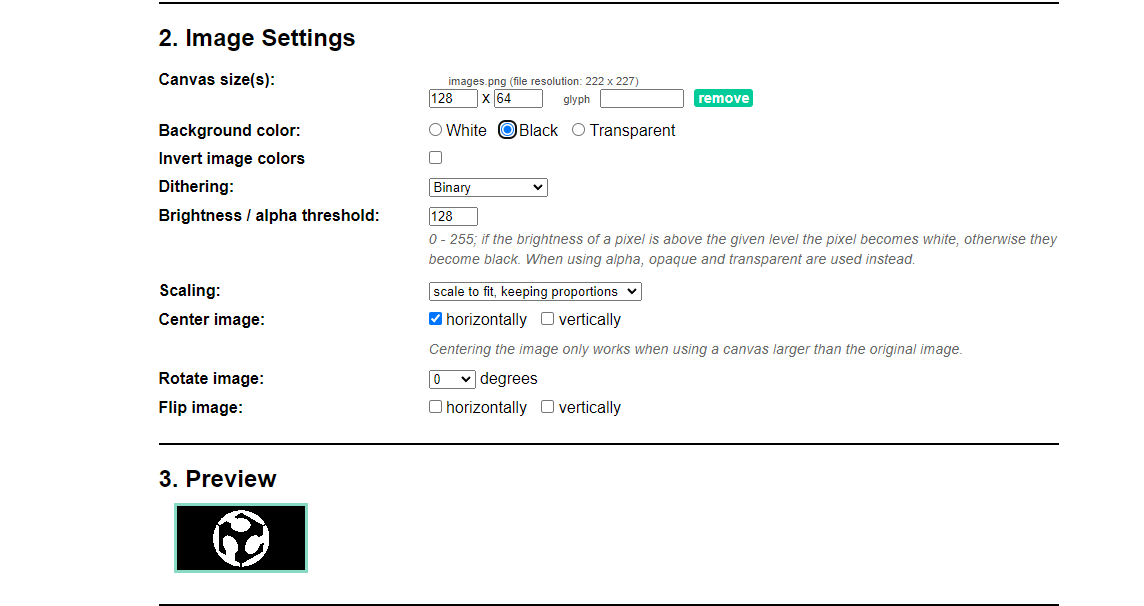
Steps to Convert an Image to Hexadecimal Data Using Image2cpp
- Go to Image2cpp.
- Upload the image using "Choose file".
- Set the output dimensions according to your screen.
- Adjust the options:
- Select the color mode and output format as hexadecimal.
- Adjust rotation and mirroring if necessary.
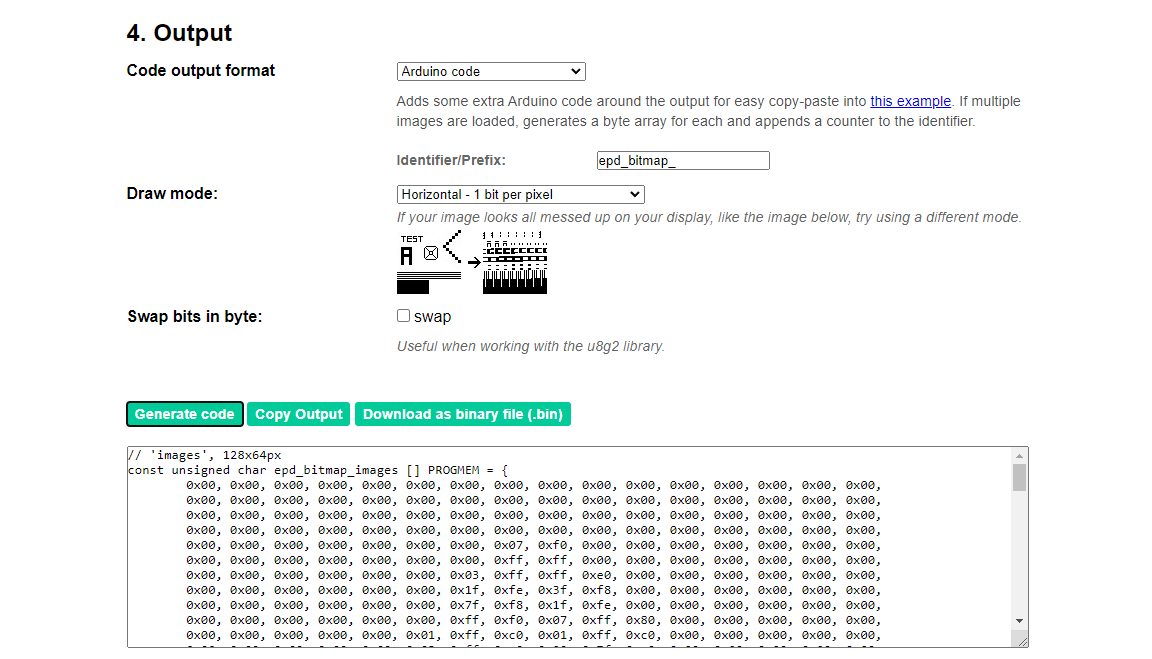
- Generate the code by clicking "Generate Code".
- Copy the generated code and paste it into your project.
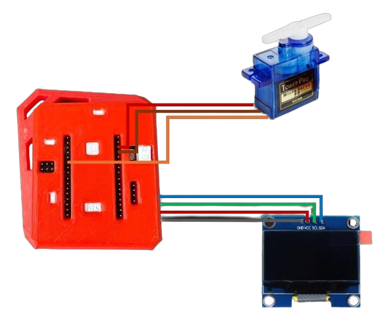
connections
The connections made for the practice can be seen below. The OLED screen was connected directly to the pins coming out of the board. The servomotor was connected using jumpers. To see the corresponding pins, visit the page for week number 8.
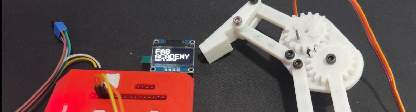
final results
These are the results for week 9. You can see how the OLED screen displays the FAB logo for a few seconds when the program starts, followed by "FAB Academy, week 9, outputs." Next, it shows the current angle of the servo. Finally, I used a small, widely available claw to make it look more appealing. You can find the STL model of the claw at the following link STL Model.
what I learned?
Thanks to this practice, I learned what a digital output is and how, with the help of a digital output, we can generate pulses called PWM to simulate analog outputs. This practice will be very useful for my final project and any other project I have in mind, as this is a key concept in electronics and how it works.