14. Interface and Application Programming
On this week I learned how to create an interface using QT Designer and how to connect this interface to a microcontroller. To fully understand this week, you should check the week13. This week uses Serial communication beetween the interface and the microcontroller. To visit the group website, click here. Finally, for this week, you should install QT Designer and Python, to install Python, you can check the tutorial on my week11.
QT Designer
Qt Designer is part of Qt, which is a very popular, cross-platform graphical user interface (GUI) builder tool for applications with highly customizable interfaces. Qt Designer makes it very easy for a designer to define and even lay out the user interfaces of a program easily using the drag-and-drop interface, making the difficult task of creating complex designs quite easy. It supports all types of widgets: buttons to text fields and even layout managers. It can be easily added to the interface of an application. Designed UI can be saved in XML format, which can later be converted into Python or C++ code, therefore providing a versatile tool for quick prototyping to production-quality application development. One of its main features, Qt Designer, can be applied in several development environments including PyQt and PySide for Python and Qt for C++. This will allow developers to tap fully into components offered from a broad Qt library: internationalization, accessibility, and multimedia formats support. The Qt Designer provides features of signal editing, slot editing, and property editing. It offers support for custom widgets; it is a complete tool that lets the developers design user interfaces that are much more exact and functional. The Qt Designer is still the tool of choice for crafting clean, professional applications that run on any platform from desktop to mobile to embedded.
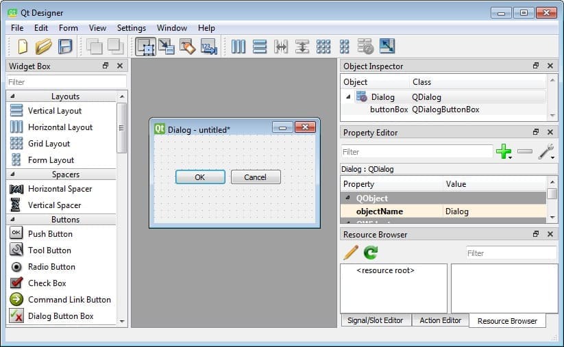
These are the parts of the QT Designer Interface. Each part is very important because it contains useful tools for the development of the interface:
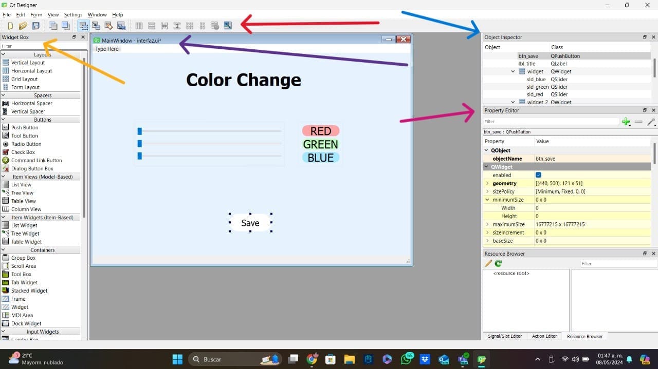
- Main Toolbar: Pointed by the red arrow, this part provides quick access to commonly used actions, such as creating a new form, opening an existing form, saving, and switching between design and preview modes. It also includes buttons for aligning and distributing widgets.
- Widget Box: Pointed by the yellow arrow, it contains a list of all the widgets that can be used to build the interface. Widgets are grouped into categories such as Buttons, Display Widgets, Item Views, Containers, etc. Users can drag and drop these widgets to add them to the interface.
- Form Edito: Pointed by the purple arrow, this is the central part of the interface. This part is where developers can drop the widgets allowing to place and resize each widget.
- Property Editor: Pointed by the pink arrow, this is the part displays the properties of the currently selected widget. It allows to view and modify widget size, font, color, and behavior properties.
- Object Inspector: Pointed by the blue arrow, it provides a hierarchical view of all the widgets and layouts. It shows the relationships between widgets.
My Interface
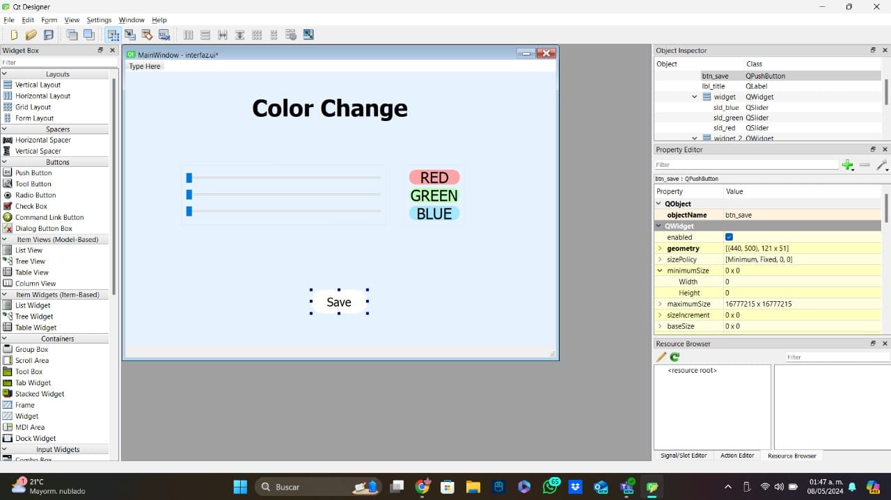
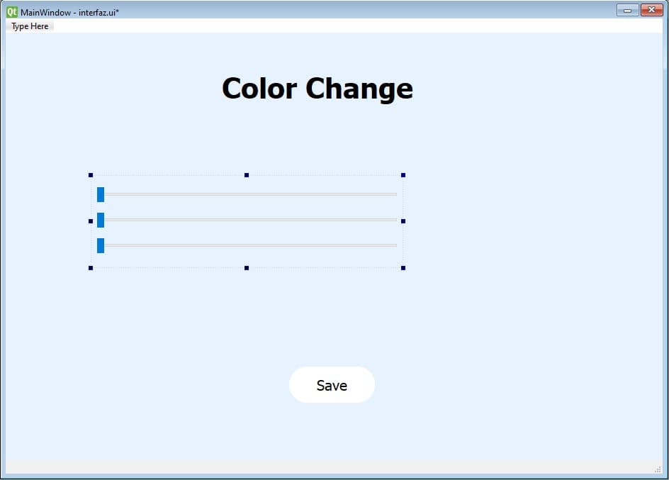
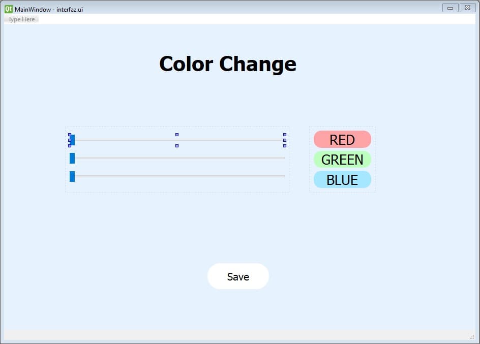
I don't have a lot of experience using QT Designer and making interfaces, so I did something simple but useful. For this interface I used 3 horizontal sliders that would control the 3 different color (RGB) of a Neopixel LED. The interface design was very simple, it has the 3 sliders for the colors, 3 boxes to indicate which slider controls each color, and finally a button for saving the combination of colors.
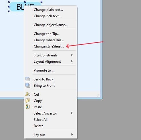
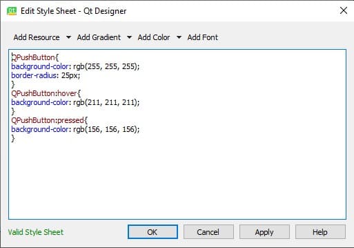
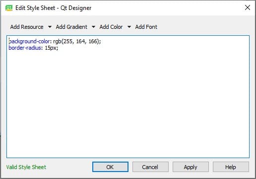
For changing the style of any of the components, you can right click them and go to "ChangestyleSheet". This option will open a CSS code to modify the component.
Now, I am going to explain how I created my interface:
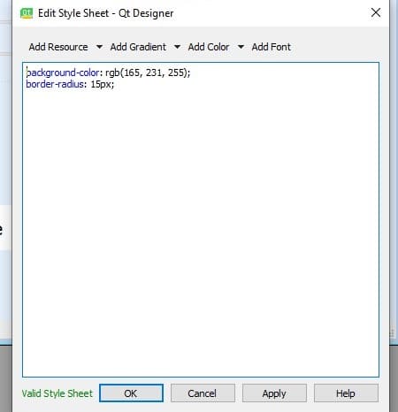
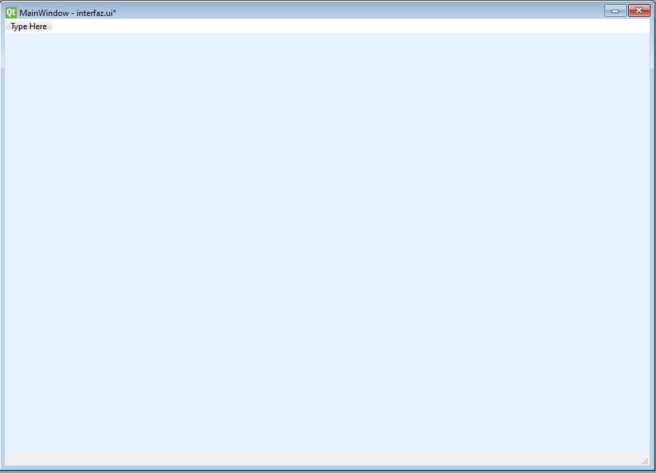
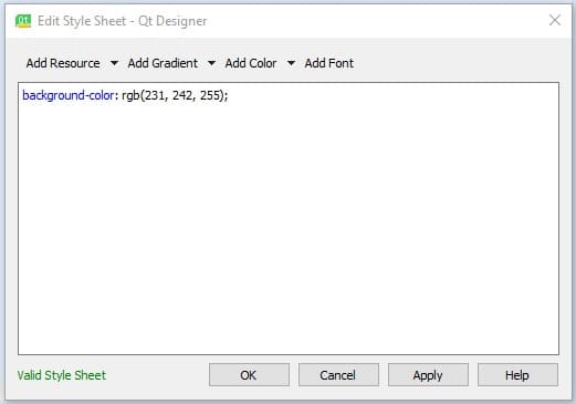
- Background: The first thing I did, was creating a label used to change the background color.
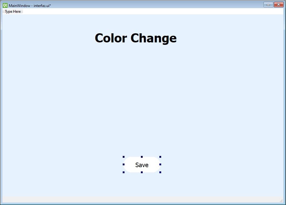
- Button: Now, I added the tittle using a text label an I added the "save" button. I added a style to this button in order to have a little click animation.
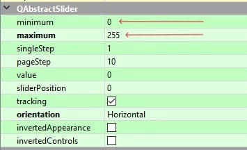
- Sliders: Then, I added a label that will have inside the 3 horizontal sliders used for the color changing. These sliders doesn't have any stylesheet, but I changed the maximun and minimun values.
- Colors: Finally, I added another label with 3 boxes that represents each of the RGB colors. This boxes are only used to know which color intensity you are changing.
Qt Designer will save the interface with a ".ui" extension. To connect the interface to a microcontroller, we will need to convert the interface to a ".py" extension. To do this, we will need to open the terminal, go to our interface folder and use the command "pip install PyQt6 pyserial". All the commands used on this section need Python installed, so if you don't have it, install it now!!
Once we install PyQt6 on the folder, it is time to convert the interface to Python. To do this, we used the followin command: "pyuic6 -x interface.ui -o interface.py". The Python file will be on the same folder of the ".ui" and will have the name you used on the command. To simulate the interface on the Python file, we can use the command "python interface.py" or "py interface.py".
If you change anything about the interface, you will have to convert the interface back to python using the aforementioned command, by doing this you will lose all the changes you have made. To avoid this, we will create another Python file in the same folder with the name "app.py" where we will paste this code:
from interfaz import *

class MainWindow(QtWidgets.QMainWindow, Ui_MainWindow):
    def __init__(self, *args, **kwargs):
        QtWidgets.QMainWindow.__init__(self, *args, **kwargs)
        self.setupUi(self)
        # The Logic


if __name__ == '__main__':
    app = QtWidgets.QApplication([])
    window = MainWindow()
    window.show()
    app.exec()
In the code above, there is a part where it says "The Logoc", in that part is where we are going to use the Serial communication to control our PCB. Now, I am going to explain both of my codes. The Python one (the interface) and the Arduino one (the PCB).
Python Code:
	self.serial = serial.Serial('COM22',9600)
        self.sld_red.sliderMoved.connect(self.sldred)
        self.sld_green.sliderMoved.connect(self.sldgreen)
        self.sld_blue.sliderMoved.connect(self.sldblue)
        self.btn_save.clicked.connect(self.sendColors)
	def sldred(self):
        sld_red = self.sld_red.value()
        print(sld_red)

    def sldgreen(self):
        sld_green = self.sld_green.value()
        print(sld_green)

	...
	def sendColors(self):
        red_value = self.sld_red.value()
        green_value = self.sld_green.value()
        blue_value = self.sld_blue.value()
        self.serial.write(f"{red_value},{green_value},{blue_value}\n".encode())
Arduino Code:
#include < Adafruit_NeoPixel.h >

#define PIN 12         // Define el pin para el LED NeoPixel
int Power = 11;
#define NUMPIXELS 1    // Número de píxeles NeoPixel
String String_received="0";

Adafruit_NeoPixel pixels(NUMPIXELS, PIN, NEO_GRB + NEO_KHZ800);
void setup() {
  pixels.begin();
  Serial.begin(9600);
  pinMode(Power,OUTPUT);
  digitalWrite(Power, HIGH);

}
void loop() {
  if (Serial.available() > 0) {
    // Espera a recibir datos del formato "R,G,B\n"
    String_received = Serial.readStringUntil('\n');
    int firstCommaIndex = String_received.indexOf(',');
    int lastCommaIndex = String_received.lastIndexOf(',');

    int red = String_received.substring(0, firstCommaIndex).toInt();
    int green = String_received.substring(firstCommaIndex + 1, lastCommaIndex).toInt();
    int blue = String_received.substring(lastCommaIndex + 1).toInt();

    // Establece el color del primer pixel
    pixels.setPixelColor(0, pixels.Color(red, green, blue));
    pixels.show();  // Actualiza el color en los LEDs
    Serial.print(String_received);

  }
  Serial.print(String_received);
}
Result
This is a video of the final result:
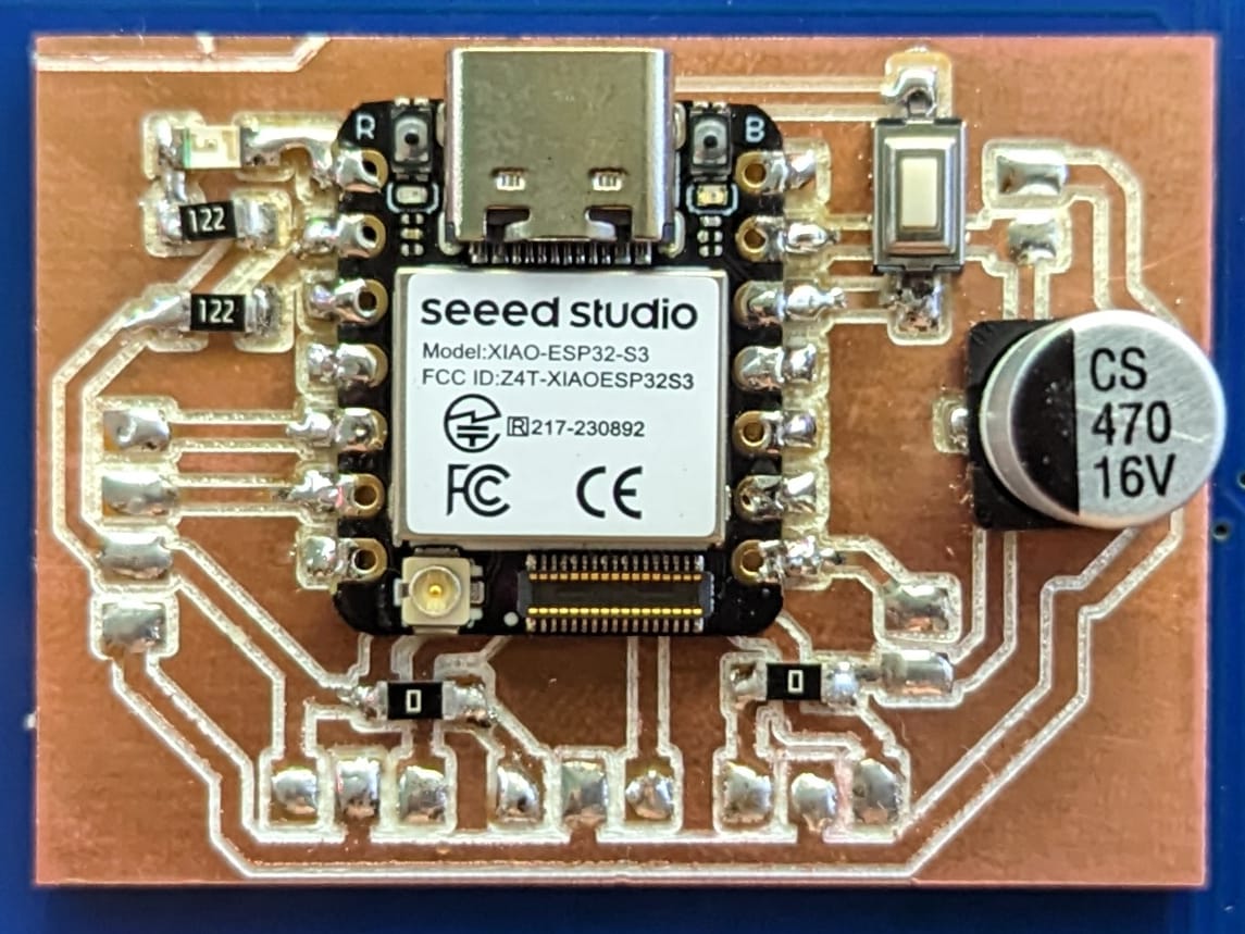
For finishing this week, I connected a Neopixel to my final project's PCB in order to complete all the tasks, the only change I made on the code was the Neopixel pin changing it to 3. Here are the photo of the PCB and its video working with the Neopixel (I connected the neopixel to one of the servo pins):
To download the files used for this week, you can click here.